1
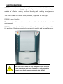
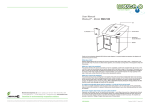
FUSION ● ● S-2850M ● Semi-automatic Gyroscopic Mixer ● User ‘ s Manual FUSION User’s Manual -1- Declaration of compliance with the CE regulations Directives 89/392/EEC HERO EUROPE S.r.l. Fraz. Buretto, 12/A 12041 – Bene Vagienna (CN) ITALY TEL.+39.0172.65.48.66 FAX.+39.0172.65.48.87 [email protected] http://eu.hero.ca Hereby declares that Semi Automatic Mixer FUSION designed and manufactured for automatically mix “non-deflagrating” coatings and paints in round,square or oval based cans or buckets made of plastic or metal. The signatory to this agreement STATES, on his own responsibility, that the machine referred to in this statement complies with the provisions set forth in: Council Directive 98/37/EEC, as amended by directive 98/79/EEC (Machinery) and incorporated into national legislation Council Directive 73/23/EEC, as amended by directive 93/68/EEC (Low Voltage) and incorporated into national legislation Council Directive 89/336/EEC, as amended by directives 91/263/EEC, 92/31/EEC,93/68/EEC and 93/97/EEC (Electromagnetic Compatibility) an d incorporated into national legislation Furthermore, the machine abides by standards IEC EN 60204-1 (April 1998) and UNI EN 292 (November 1992) Alessandro Sacchet Chairman HERO EUROPE S.r.l. FUSION User’s Manual -2- User’s Manual Gyroscopic Digital Mixer FUSION Version 1.00 (February 2008) © COPYRIGHT 2008, HERO EUROPE Srl all rights reserved. No part of this manual may be reproduced in any form, or by any means, electronic or mechanical, including photocopying and recording, without prior written permission of HERO. Information in this manual is subject to change without notice and does not represent a commitment on the part of HERO. Unless otherwise indicated, all references to companies, names, data and addresses used in the screens and / or examples are purely coincidental and serve only to clarify the use of the HERO product. HERO shall not be liable for technical or editorial errors or omissions made herein; nor for incidental or consequential damages resulting from the performance or use of this material. If you require additional copies of this manual or further technical information about it, please write to: HERO EUROPE S.r.l. Frazione Buretto 12/A - 12041 - Bene Vagienna (CN) – Italy TEL.+39 (0172) 654866 FAX +39 (0172) 654887 mailto: [email protected] http://eu.hero.ca FUSION User’s Manual -3- INDEX 1. SAFETY INSTRUCTIONS…………………………………….………………. 5 2. INTRODUCTION………..………………………..………….………………… 6 3. TECHNICAL SPECIFICATIONS………………………………….…………. 7 4. WARRANTY TERMS……………………………………………………..……. 9 5. GENERAL DESCRIPTION……………………………………………………. 10 6. SAFETY SPECIFICATIONS………………………………….………………. 11 7. INSTALLATION…………………………………………………………..……. 15 8. CONTROLS……………………………………………………………….……… 16 9. OPERATIONS……………………………………………………………….….. 18 10. MAINTENANCE & TROUBLESHOOTING…………..……………………. 22 11. SCHEMATIC DIAGRAM ……………………………………………………… 25 FUSION User’s Manual -4- SAFETY INSTRUCTIONS This product is NOT EXPLOSION PROOF. FLAMMABLE SUBSTANCE. Do not mix, or clean with, a Read this manual before using this product. Only trained and authorized personnel shall use this product. This product is equipped with a cord having a grounding wire with an appropriate grounding plug. The plug must be plugged into an outlet that is properly installed and grounded in accordance with all local codes and ordinances. This product is for use on a nominal 115 or 230 Volt circuit, as shown on the nameplate. Only connect the product to an outlet having the same configuration as the plug This product shall be connected to a dedicated electrical circuit – no other devices shall be connected to this circuit. Removal of the plug from the outlet is the means for isolating the mixer from the power supply. Ensure that the mixer is installed with the plug easily accessible to the operator. This product is designed to operate only when the door is closed. DO NOT ATTEMPT TO ALTER ELECTRICAL INTERLOCK MECHANISM A failure of the door interlock system must be repaired immediately in order to avoid injury from improper operation. Contact the manufacturer or certified service personnel In case of emergency, press the Red Emergency Stop button. Do not mix cans shorter than 70 mm (2¾ in), or 185 mm (7 5/16‖) with bail holder installed. Do not mix cans weighing more than 35 kg (77 lb) FUSION User’s Manual -5- 2. INTRODUCTION FUSION is a revolutionary new heavy duty mixer, which is ideal for all your mixing requirements. FUSION Mixer performs gyroscopic action, which enables in effective mixing, uniform blending and making homogeneous mixer. This mixer is ideal for mixing small, medium, large cans up to 45kgs. FUSION is user friendly. The dimension of the machine makes it versatile and suitable for use in all environments. FUSION is a rugged and reliable mixer which performance and design exhibits the qualities of a strong and sturdy engineering product and low maintenance . HERO shall not be liable for any damage or injury incurred by non-compliance with these regulations, or by not taking the usual and accepted precautions in handing, operation or repair, even if not expressly stated in this manual. FUSION User’s Manual -6- 3. TECHNICAL SPECIFICATIONS FUSION – 8 x 6 ACT. FEATURES WIDTH 900 mm DEPTH 810 mm HEIGHT 1210 mm MACHINE WEIGHT 205 kg MAXIMUM CAN WEIGHT 35 Kg MAXIMUM CAN DIAMETER 340 mm MINIMUM CAN DIAMETER 60 mm MAXIMUM CAN HEIGHT 400 mm MINIMUM CAN HEIGHT 70 mm CASTOR WHEEL AVAILABLE ADJUSTABLE FOOT AVAILABLE CLAMPING MANUAL MAIN MOTOR 1 HP, Single Phase, 220/110 VAC, 50-60 Hz, 14401725 RPM RATIO BETWEEN ASSEMBLY VS MOTOR RATIO BETWEEN ASSEMBLY VS BOTTOM DISC 1 : 14 1:2 BRAKE AVAILABLE ON ACCUTATOT BRACKET MAXIMUM NOISE LEVEL 55 Db 100 rpm STIRRING VELOCITY SINGLE SPEED - ALL CANS MAXIMUM CLAMPING CLEARANCE 410 mm POWER SUPPLY 220 V / 50 - 60 Hz; MAGNETOTHERMIC S/W FOR 220 240 V 16 Amp MAGNETOTHERMIC S/W FOR 115 V 25 Amp EMERGENCY SWITCH AVAILABLE BREAK RELEASE SWITCH AVAILABLE DISPLAY AVAILABLE (PLC) LOCKING DOOR DEVICE (SAFETY DOOR S/W) AVAILABLE ERROR MESSAGES AVAILABLE ON PLC GYROSCOPIC MOTION CLOCKWISE AUTOMATIC ASSEMBLY POSITIONING NA CAN COUNTER WITH TIME LOOPING NA LIFE TEST CYCLE COUNTER AVAILABLE LIFE TEST BREAK COUNTER AVAILABLE ROLLER FOR CAN SLIDE AVAILABLE TRANSMISSION BELTS 2 NOS ACCESS TO TRANSMISSION BELTS REMOVABLE BACK PANEL FUSION User’s Manual -7- 110 V / 60 Hz PROGRAMEBLE LOGIC CONTROL PLC – 8 x 6 LINE VOLTAGE – 24 VDC LINE POWER – 2W INPUT 24 VDC RELAY MODULE AS -393 24 V OM, 4CH , 2 C/O, 24 VDC COIL,ISOLATED , OMRON SOLDERED. MOTOR RELAY 24 VDC , 30 A ,110-220 VAC . TIMER MECHANICAL DOOR PLASTIC SHUTTER WITH METAL BARS FOR SAFETY (UP TO 6 MIN) EN 292 Part 1 and 2: 1991 Safety of Machinery – Basic concepts, general Principles for design EN 418: 1992 Safety of Machinery – Emergency stop equipment, Functional aspects EN60204 Part 1: 1997 Safety of machinery – Electrical equipment of Machines -Specifications for general requirements. EN 954-1: 1996 Safety of Machinery – Safety related parts of control Systems- Part 1: General principles for design EN 1088: 1995 Safety of machinery-Interlocking devices associated With guards EN 294: 1992 Safety of machinery – Safety distances to prevent danger zones being reached by the upper limbs. EN 953: 1997 Safety of machines – Guards-General requirements for the design and construction of fixed and movable for coating materials PrEN 12757-1 Mixing machinery for coating materials - Materials used by HERO to manufacture the machine doesn’t undergo corrosions or deteriorations (They are compatible) with the paints which have to be mixed. - If requested will be supplied the list of the used materials for the construction of the machine, to assure the compatibility with the paints which have to be mixed. FUSION User’s Manual -8- 4. WARRANTY TERMS LIMITED WARRANTY: HERO warrants each unit manufactured to be free of defects in material and workmanship for a period of twelve months. The part unit shall be returned with transportation charges prepaid. If the fault has been caused by misuse or abnormal conditions of operation, repairs will be billed at a normal cost. In this case, an estimate will be submitted before works is started, if requested. Always include serial number in any correspondence concerning the part unit. The warranty expires: Twelve month after date of invoicing In case of improper use In case of non original spare parts are used In case of repair / adaptation of FUSION without written approval and/or by unauthorized personnel In case of non fulfillment of the maintenance-, operation-,or other instruction, like e.g. reflected in this manual The above conditions are valid in absence of other which was expressly agreed on. FUSION User’s Manual -9- 5. GENERAL DESCRIPTION The FUSION mixer is specifically designed for point-of-sale color mixing applications as well as for semi-industrial applications. The FUSION has been designed to meet the demands of the retail market. The unique design results in reduced maintenance and in color mixing at the lowest cost per liter produced. FUSION User’s Manual - 10 - 6. SAFETY SPECIFICATIONS Compliance with safety requirements: This mixer must be used and serviced by authorized and trained personnel only. Improper use or servicing may result in dangerous situations or accidents. Risk to personnel is possible in two areas: Operator area Maintenance area Operator area Maintenance area THIS EQUIPMENT MUST BE GROUNDED. Attention!!! Connect this product to a dedicated electrical circuit – no other devices shall be connected to this circuit. Do not use extension cords to connect this product. Attention!!! Only trained personnel shall be permitted access to the electrical wiring within the machine. DO NOT USE THIS PRODUCT IF THE BACK PANEL IS NOT IN PLACE. The machine is equipped with a power supply cable having the following specifications: Length: 8 FT Size: 14 AWG FUSION User’s Manual - 11 - The machine shall be connected to a dedicated, grounded circuit, protected by a 15 A circuit breaker. All wiring shall be in accordance with local codes Important: The power supply cable conductors GREEN or GREEN/YELLOW WHITE or BLUE/BLACK BLACK or BROWN/RED are color-coded as follows: — GROUND — NEUTRAL — LINE Service safety rules: 1. Prior to performing any maintenance or inspection of the FUSION disconnect the power plug from the electrical outlet in order to ensure that the FUSION cannot start unexpectedly. 2. To prevent injuries to personnel ensure that all removable panels are in place and properly secured except for any necessary inspections or maintenance. 3. Do not disable or override any of the installed safety features such as the door lock system. 4. The FUSION shall be installed in an environment conforming to the appropriate local regulations. A permit issued by the local authority may be required. Keep the number of paint cans in the immediate area of the machine to a minimum. 5. Do not store flammable materials or other materials inside the machine. The area in which the FUSION is installed must be kept free of exposed flames, incandescent fixtures or other devices that might create sparks. 6. It is recommended that a ventilation system, guaranteed to maintain the concentration of dangerous vapors around electrical components at less than 30%, be installed. 7. When the FUSION is not being used for a period of time (such as at the end of the work day), ensure that it is empty (no paint can inside), close the door and unplug the power plug from the outlet. 8. Ensure that all tools are removed from inside the machine after any maintenance work. FUSION User’s Manual - 12 - WARNING! Do not operate the FUSION when it is empty – operate only with a can clamped in place. Do not use with a load greater than 35 kg (77 lb). Ensure there is no can inside the FUSION when it is is switched OFF (disconnected from the electrical outlet). Do not put damaged containers in the FUSION. Damaged containers may rupture during mixing and may cause damage to the FUSION When servicing the FUSION be sure to follow the safety procedures described in this manual. The FUSION is to be operated and serviced by trained personnel only. HERO shall not be liable for any damage or injury caused by non-compliance with the procedures presented in this manual, or by not taking the usual and accepted precautions in handling, operating or servicing, even if not expressly stated in this manual. Further, HERO shall not be liable for any damage or injury resulting from changes made to the machine without prior notice to and approval from HERO. RESIDUAL RISK Residual risks list for the user: The FUSION, and its operating and service instructions, have been developed giving careful consideration to the safety of the user and service technician. However, there are situations where risks can be reduced but not eliminated completely. RISK PRECAUTION Injury or crushing during loading and unloading operations. Abrasions and injuries caused by sharp edges on the cans being used Liquid leakage form the cans being used Use protective gloves and safety shoes during loading and unloading operations. Use protective gloves during loading and unloading operations. Thoroughly clean the operator and maintenance areas. Keep these areas clean. FUSION User’s Manual - 13 - Personal protection for user: The FUSION, when properly operated and maintain, presents minimal risk to the user. However, it is recommended that the user wear suitable protective equipment (safety glasses, safety shoes with non-slip soles and gloves), in particular when loading and unloading the mixer. General danger situations: There are no specifically identified hazard related to the operation and maintenance of the FUSION (e.g. fire risk, issue or dispersion of dangerous products). However, it is recommended that a powder type fire extinguisher, suitable for electrical fires, be readily accessible. Safety devices: The machine is equipped with the following safety devices: Emergency Stop Button Door Lock and Sensor Emergency Stop Button For safety reasons, all users should know the location of the Emergency Stop button, and how to use it. The RED Emergency Stop push button is located on the Left Hand control panel on the top front of the mixer – to the left of the door. Pushing the button will immediately cut power to the motor control relay, stopping the motor. To reset the button and restore the mixer to normal operation mode, rotate the button clockwise. Door Lock and Sensor The FUSION is equipped with a safety device which prevents start up of the mixing cycle when the door is in the open position. It also locks the door in the closed position during the mixing cycle. FUSION User’s Manual - 14 - 7. INSTALLATION INSTALLATION CONDITIONS: Before unpacking and installing the FUSION Mixer, please make sure of the following: The crate/packaging in which the FUSION was shipped has not been damaged in any way. The floor on which the FUSION is to be located is firm and level An electrical receptacle on a properly grounded, dedicated, 15 A, 115 or 230 V circuit is available in the immediate vicinity. The circuit shall be installed in accordance with local codes. The receptacle shall be of a configuration appropriate for the voltage and current rating of the circuit. INSTALLATION: It is recommended that, during the installation of the mixer, protective gloves be worn in order to prevent hand injuries. Unpack the FUSION Mixer. Ensure the machine has not been damaged in any way Position the mixer in the desired location. It is equipped with rollers to aid in positioning. Using the four leveling feet, level the machine, ensuring that all four feet are properly supporting the machine. Lock the leveling legs in place by tightening the jam nuts. FUSION User’s Manual - 15 - 8. CONTROLS LEFT HAND CONTROL PANEL Emergency Stop Button Unlock Button – Can Holder Assembly Lock (Functions Only When Mixer Stopped) RIGHT HAND CONTROL PANEL – MECHANICAL TIMER START Button - Illuminated GREEN when mixer running STOP Button - Illuminated RED - door is unlocked - Slow flashing RED – waiting for door to unlock - Fast flashing RED – Error Condition Mechanical Timer - sets mixing time PROGRAMABLE LOGIC CONTROL – 8 X 6 FUSION User’s Manual - 16 - RELAY MODULE /MOTOR RELAY FUSION User’s Manual - 17 - 9. OPERATIONS TURN ON MACHINE (Connect to power): Note: The door will not open until the FUSION mixer is connected to the building power. o Ensure the Emergency Stop button is engaged – push to engage if necessary o Plug the mixer into the appropriate electrical receptacle. Ensure the circuit breaker on the left hand side the mixer, near the top rear corner, is ON. Mechanical Timer: The STOP button will light up RED for a few seconds then start to flash slowly. Release the Emergency Stop button by turning it clockwise. The STOP button will continue to flash slowly for a few seconds then change to continuously illuminated RED (not flashing) and the door will unlock. Electronic Timer: The LCD Display will come on, displaying an error message. Release the Emergency Stop button by turning it clockwise. After a short delay, the LCD Display will show ―0:00‖, the ―Door Unlock Indicator‖ will light up and the door will unlock. CAN LOADING: 1. Open the FUSION Mixer door to its fully open position. 2. Ensure the Can Holder Assembly is in the vertical, top dead center (TDC) position, with the Clamp Actuator Mechanism at the top, and locked in place. If it is not, use the two handles on the front of the Can Holder Assembly, to rotate it to the TDC position. Ensure the lock mechanism engages and the Can Holder Assembly is locked in place. FUSION User’s Manual - 18 - 3. Referring to the illustrations, open the Can Clamping Plates as follows: o L i f t X Y Z t h e o o o o o o o o L e v e r Lock (X) and rotate it 90º to expose the levers (Y & Z). Rotate the levers to the vertical position. Using the levers, rotate the clamp actuator mechanism anticlockwise to open the clamping plates. Position the can on the bottom plate. Using the concentric rings on the bottom plate as a guide, ensure the can is properly centered. Using the levers (Y & Z), rotate the clamp actuator mechanism in clockwise direction to securely clamp the can between the plates. Rotate the levers (Y) to the horizontal position. Rotate the Lever Lock 90º to cover the levers and lock the mechanism. Ensure the locking mechanism has properly engaged by rotating the clamp actuator mechanism slightly clockwise and anti-clockwise. Ensure the Lever Lock is in the correct position, parallel to the handle (Z). Close the door to the fully closed position. Note: Do not force the door. If the clamp actuator mechanism interferes with the closing of the door, adjust the mechanism, ensuring the levers (Y) and Lever Lock (X) are correctly positioned. FUSION User’s Manual - 19 - MIXING: Mechanical Timer: o Set the desired mix time by turning the knob on the mechanical timer to the appropriate position. o Push the ―START‖ button to start the mixing cycle. The ―START‖ button will be illuminated GREEN and the light on the ―STOP‖ button will turn OFF. The door will lock, the Can Hold Assembly Lock will disengage and the Can Holder Assembly will spin for the set time to mix the paint. Once the set time has expired, the ―STOP‖ button will slowly flash RED, the light in the ―START‖ button will turn OFF and the Can Holder Assembly will come to a stop. The light in the ―STOP‖ button will the stop flashing (staying ON) and the door will unlock. To STOP the mixer during an emergency situation, push the Emergency Stop button. Once the machine has stopped, release the Emergency Stop button by turning it clockwise. The door will unlock. USE THE EMERCENCY SITUATION ONLY STOP BUTTON IN AN EMERGENCY Electronic Digital Timer: o Set the desired mix time using the ―+‖ button to increase or, if necessary, the ―-‖ button to decrease the value. The set time will be displayed on the Digital display o Push the ―START‖ button to start the mixing cycle. The ―Door Unlock Indicator‖ will go OFF, the door will lock, the Can Hold Assembly Lock will disengage and the Can Holder Assembly will spin for the set time to mix the paint. o If it is necessary to stop the mix cycle before the set time expires, push the ―STOP‖ button. To STOP the mixer during an emergency situation, push the Emergency Stop button. Once the machine has stopped, release the Emergency Stop button by turning it clockwise. The door will unlock. USE THE EMERCENCY SITUATION ONLY FUSION User’s Manual STOP - 20 - BUTTON IN AN EMERGENCY Note: Pushing the Emergency push button during the cycle the display will show an error message. Note: Always remove the can from the mixer after the mix cycle has been completed. Follow the UNLOADING instructions. below. UNLOADING THE CAN: 1. Open the FUSION Mixer door to its fully open position. 2. Using the two handles on the front of the Can Holder Assembly, slowly rotate the Assembly to the vertical, top dead center (TDC) position, with the Clamp Actuator Mechanism at the top. When it reaches this position the Clamp Assembly Lock will engage, locking it in place. Note: If, for some reason, it is necessary to rotate the Can Holder Assembly after the lock has engaged, depress and hold the yellow ―Unlock‖ button. Rotate the assembly off the TDC position and release the yellow button. The lock will remain in the disengaged position until the assembly is returned to the TDC position. 3. Open the Can Clamping plates as follows: o o o Lift the Lever Lock and rotate it 90º to expose the levers. Rotate the levers to the vertical position. Using the levers, rotate the clamp actuator mechanism anticlockwise to open the clamping plates. FUSION User’s Manual - 21 - 10. MAINTENANCE & TROUBLESHOOTING Monthly Maintenance: 1) Apply grease on Guide shaft of EP 90 Lithium base 2) Apply grease also on Spine (Below the Bottom Disc) Troubleshooting: PROBLEM Machine is not turning on Brake not operating Main Motor not running / working 1) 2) 3) 4) 5) 1) 2) 3) 4) 1) 2) 3) 4) 1) Machine vibrates during operation Machine makes a loud noise after every revolution Container clamped does not rotate along its axis even though the machine is rotating. TROUBLE SHOOTING Check the Mains supply. Check MCB Position, it should be ON. Check the Power supply Check plug or lose wire. Check motor belts. Check the Push button Check the Brake coil Check Brake Power supply Check brake mechanism in motor. Check the Actuator , Solenoid limit switch Check Emergency switch Check Motor mechanism and Motor capacitor. Check supply on PLC ,Relay card & Motor Relay. Check the floor flatness. If the floor surface is not plain, then shift the Machine on a plain / flat surface. 1) Check the foundation of the Motor. 2) Check the tension of the belt joining the Motor pulley and the Main Wheel. If found loose, adjust it to the proper tension. 3) Check whether the belt has worn out. If yes, then replace the same with a new one. 1) Check the ―V‖ belt for proper tension. 2) If the belt is found loose then replace the same with a new one. Clamped container becomes loose The locking springs need to be replaced. Clamping bracket does not slide smoothly. Machine is giving shock while in operation Clean the Guide Shafts and apply the general-purpose grease Check for proper grounding. If the earthing is not proper consult an electrician. FUSION User’s Manual - 22 - Timer Failure Break Release Push button Relay Card Failure Proxy Failure Check Power ON Rotate Timer Knob (I4 Display on PLC Screen) Reset Knob (I4 Display off on PLC Screen) Check the wire connection on the Break release push button. Defective Break release push button. Check the cable connection. Check Input Supply 24 VDC. Check Indicator R1,R2,R3,R4 If it is glow check wire. Check the home proxy position. Check the cable connection of home Proxy. Note: Shutter will not open when the Power is OFF Visualization Errors on PLC Following errors to be arranged in proper way Emergency Press Door Switch Faulty Actuator Faulty Information Display on PLC Cycle Start Cycle Stop Cycle Counter - Press Push Button Reset Counter - Press Push Button Break Counter - Press Push Button System Error : Emergency Press on PLC 30 Sec. on PLC on PLC System Error : Door Switch Faulty FUSION User’s Manual Turn the emergency push button to Clockwise direction. Check the wire connection on the emergency push button. Defective emergency push button cable. Check PLC Connection. Check PLC screen I7 should be +24 VDC. Check Position of Door. Check the cable connection of Door Switch.(If its Photo sensor Check reflector light) Check Reflector - 23 - System Error : Actuator Faulty Check the wire connection on the Actuator motor/Solenoid Micro Switch.( I5 should be 0V) If it is Actuator Motor, Check supply in Transformer or SMPS Input - 230/110 VAC & Output 24 VAC. Check Proxy Connection & Position. If Micro Switch Fail. Actuator Shaft not Travel back. Adjusting Transmission Belts: Remove back panel from the machine. Check belt tension, which should bend 5 – 10mm while pressed with fingers in its side. To Correct the tension, do/undo the bolt (13mm) as shown in the picture. Check the belt by rotating the main pulley. The belt should not be worn. Put the back panel in its original position. Actuator Motor – Only in FUSION STD : Remove back panel from the machine to view the Actuator motor. Just above the belt tension adjustment bolt the Actuator motor has been mounted. It has been used to work as break to hold the Main wheel. FUSION User’s Manual - 24 - 11. SCHEMATIC DIAGRAM FUSION 8 X 6 ACT FUSION User’s Manual - 25 - ABRAVATION AMI - Actuator Micro Switch SMI - Solenoid Micro Switch TMR - Mechanical Timer STR - Start Button STP - Stop Button PTO - Push to Operate EMR - Emergency PXY - Proxy GL - Green Light RL - Red Light DOR SOL - Door Solenoid LCK SOL - Gyro Lock FUSION User’s Manual - 26 -