1
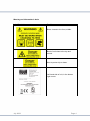
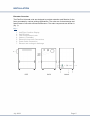
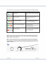
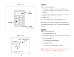
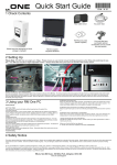
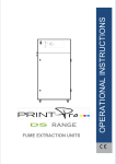
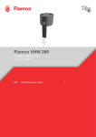
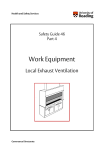
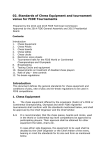
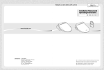
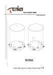
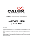
OPERATIONAL INSTRUCTIONS
PRINTPro Universal
FUME EXTRACTION UNITS
July 2009
Page 1
TABLE OF CONTENTS
TABLE OF CONTENTS ............................................................................................ 2
SAFETY INSTRUCTIONS......................................................................................... 3
Symbols used ................................................................................................................ 3
Electrical safety............................................................................................................. 3
Dangers to eyes, breathing and skin ............................................................................ 3
Warning and Information Labels .................................................................................. 4
INSTALLATION......................................................................................................... 5
Extractor Overview ....................................................................................................... 5
Extractor Installation Procedure .................................................................................. 6
Optional Feature Considerations ................................................................................. 7
Filter blocked / System failure signal............................................................... 7
Remote stop / start. ........................................................................................ 7
Electrical supply connection ......................................................................................... 8
General Safety Requirements ...................................................................................... 8
OPERATION ............................................................................................................. 9
Manual operation ......................................................................................................... 9
Setting The Air Flow......................................................................................... 9
Gas Filter Change LED (VOC monitoring) ........................................................ 9
Optional Feature .......................................................................................................... 9
MAINTENANCE ...................................................................................................... 11
Fuses ........................................................................................................................... 11
Cleaning ...................................................................................................................... 11
Gas Filter / Combined filter replacement................................................................... 11
Pre filter replacement ................................................................................................ 12
UV PRINTERS ................................................................................................. 12
INK SOLVENT PRINTERS ................................................................................. 12
Consumable Spares .................................................................................................... 13
Maintenance Protocol ................................................................................................ 13
Filter Disposal ............................................................................................................. 14
TROUBLE SHOOTING ........................................................................................... 15
APPENDIX .............................................................................................................. 16
System Specifications ................................................................................................. 16
July 2009
Page 2
SAFETY INSTRUCTIONS
Symbols used
Danger
Refers to an immediately impending danger. If the danger is
not avoided, it could result in death or severe (crippling) injury. Please
consult the manual where this symbol is displayed.
Warning
Refers to a possibly dangerous situation. If it is not avoided, it
could result in death or severe injury. Please consult the manual
where this symbol is displayed.
Caution
Refers to a possibly harmful situation. If it is not avoided,
damage could be caused to the product or to something in its
environment.
Important
Refers to handling tips and other particularly useful information. This
does not signify a dangerous or harmful situation.
Electrical safety
The PrintPro Universal range of extraction units are designed to meet the safety
requirements of the Low Voltage Directive 2006/95/EC (previously numbered
73/23/EEC) and UL 61010-1.
Warning
During works with the pump/motor housing open, mains voltage
components are accessible. Make sure that rules and regulations
for work on live components are always observed.
Important
To reduce the risk of fire, electric shock or injury:
1. Always isolate the system from the mains power supply before removing
the pump/motor panel
2. Use only as described in the manual
3. Connect to a properly grounded outlet
Dangers to eyes, breathing and skin
Once used, the filters within the extraction units will contain a mixture of particulates,
some of which may be sub micron size. When the used filters are moved it may
agitate some of this particulate which could get into the breathing zone and eyes of
the operative. Additionally, depending on the substances involved, the particulate
may be an irritant to the skin.
Caution: When changing used filters always wear mask, safety glasses and gloves.
Please note the media in the gas filter fitted in this unit is capable of adsorbing a wide
range of organic compounds. However, it is the responsibility of the user to ensure it
is suitable for the particular application it is being used on.
July 2009
Page 3
Warning and Information Labels
Label/Symbol
Position
Base, closest to the front, middle
Back of unit close to the top and
central.
Next to protex clip on base.
Left hand side of unit, in the bottom
right corner.
July 2009
Page 4
INSTALLATION
Extractor Overview
The PrintPro Universal units are designed to provide extraction and filtration for the
fume generated by various printing applications. The units are of robust design and
feature ease of use with minimal maintenance. The main components are shown in
(fig. 1).
Fig. 1
1.
2.
3.
4.
5.
6.
7.
Unit/Filter Condition Display
On/Off Switch
Filter Compartment Latch
Castors (2 lockable)
Extraction Hose Inlet Connections
Power Cable Connection
Exhaust and cooling air discharge
July 2009
Page 5
Extractor Installation Procedure
Caution
If this equipment is used in a manner not specified by the manufacturer, the
protection provided by the equipment may be impaired.
Read all instructions in this manual before using this extractor.
1. Move the unit to the location where it is going to be installed and remove the unit
from its packaging. The unit should be installed in a well ventilated room.
Caution
Due to the weight involved the extractor unit should only be lifted using suitable lifting
equipment and with regard to appropriate safety precautions. (See Appendix for
product weight details).
2. Ensure that a 0.5m space is available around any louvered areas of the unit to
ensure adequate air flow. Lock the two braked castors, if fitted.
Caution
Do not block or cover any louvers or cooling holes on the unit as this severely
restricts air flow and may cause damage to the unit.
Caution
Under no circumstances should the exhaust outlet/s be covered as this will restrict
the airflow and cause overheating.
3. Check filters are located in their correct position and carefully replace lid/close
door.
4. Connect the extraction ducting between the extractor inlet and the printer using
hose adaptors and jubilee clips as required. Ducting runs should be kept as short as
possible.
July 2009
Page 6
Optional Feature Considerations
5. If fitted, the following features need to be considered when installing the unit:
Filter blocked / System failure signal.
With this option the extraction unit will have been fitted with a pressure transducer to
monitor the condition of the filters and to indicate the extractor is running. In addition
to controlling the LED’s on the front of the unit, this signal is available via the green
and white cores of the control cable that exits the cabinet next to the power cable.
The signal is a “volt free” contact, i.e. a closed circuit will exist between the green and
white wires when the filter condition is good and the unit is running. This will change
to an open circuit on filter blockage or system failure. This feature should only be
used on control voltage circuits. The signal can be connected to the laser or
alternatively to operate a beacon, siren or warning device. Open circuit condition of
this circuit will not directly stop the extractor motor (see fig 2).
Remote stop / start.
If this facility is installed it enables the extractor unit to be turned on and off by a
signal from the laser. The red and black cores of the control cable need to be
connected to a 24vdc supply, which when applied will start the unit and when
switched off will stop the unit. However the mains power switch must be in the “on”
position for the signal to be effective (see fig 2).
Fig 2
If fitted, remote operation can be overridden by using the override switch, which is
mounted inside the unit (see fig. 3).
Fig 3
July 2009
Page 7
Electrical supply connection
6. Check the integrity of the electrical power cable.
Connect the power cable to an isolated electrical supply. The mains socket outlet
should be installed near the equipment and be easily accessible. The cable run to the
machine should be arranged so as not to create a trip hazard.
Caution:
Check that the mains input at the isolated supply is the same as the voltage Supply
detail on the Serial Number label (115 or 230v 50/60Hz) before plugging the
extractor unit in.
General Safety Requirements
The mains socket outlet should be installed near the equipment and be easily
accessible.
Caution
Do not block or cover the cooling vents on the unit, as this severely restricts airflow
and may cause damage to the unit. (This may be located on the base of the unit).
Caution
This unit is over 18Kgs in weight and should only be lifted with suitable lifting
equipment.
Caution
If this equipment is used in a manner not specified by the manufacturer, the
protection provided by the equipment may be impaired.
Read all instructions in this manual before using this extractor.
Warning
Mains voltage. Dangerous voltages exist in this equipment.
Ensure all covers are fitted before operating this equipment.
The unit is now ready for use.
July 2009
Page 8
OPERATION
Manual operation
Units are turned on by depressing the power side of the switch on the front of the
extractor and turned off by depressing the off (O) side of the switch. (See fig 4).
Fig 4
Note: In order to help ensure long term reliability of
the fan unit, it is recommended that a 90 second
delay period (minimum) is observed between
stopping and restarting the extractor to prevent
possible damage to electronic components within
the fan.
Setting The Air Flow
This unit comes with a speed control feature which allows the user to set their
desired air flow. This is performed by using the potentiometer situated on the front of
the unit (see fig 5). Flow (with clean filters) can be adjusted from 200 – 380m3/h.
Fig 5
Gas Filter Change LED (VOC monitoring)
The print pro unit comes fitted with VOC (Volatile Organic Compound) monitoring,
this is done by means of a VOC sensor fitted in the exhausted air compartment. If
their presence exceeds a preset level the Alarm LED on the front panel will illuminate
(see fig 5), this indicates that the gas filter is saturated and the filter needs replacing.
The Maintenance section describes the filter change procedure.
Optional Feature
As an option, units can be fitted with a filter condition indication system which is both
VOC sensor and pressure transducer driven. In this case the front panel will be as
shown in (fig 6).
Fig 6 - Gas filter full indication - VOC monitor and filter blocked indication.
July 2009
Page 9
The four LED’s on the front panel (see table below) indicate the following conditions
LED’S
SHOWING
INDICATES
Green Only
Unit is running - Filters are usable
Green & Amber
Pre or Combined Filter 75%
blocked
Green, Amber & Red
Pre or Combined Filter Blocked
and in need of replacing
Green, Amber & Red flashing
Fault with extractor.
This condition may occur for a few
seconds on start up
Red Alarm Light
Only used with optional extra Gas
Filter Change LED
Note – When solvent ink filter option is used, filter status indication will only show
green (extraction fan operation/ vacuum ok) or green, amber and red flashing (fan
failure/ system vacuum too low).
Note – When particulate filter option is used, filter blocked will only be indicated if
flow is set above ¼ of the flow range. With blocked filter indication) illuminated, the
required minimum 200m3/h flow rate will only be achieved with flow set in the ‘max’
position (see fig 7).
Fig 7.
July 2009
Page 10
MAINTENANCE
Maintenance UK
It is a legal requirement, under regulation 9 of the COSHH regulations, that all local
exhaust ventilation systems are visually inspected on a weekly basis, where possible
and undergo a thorough inspection and test on an annual basis. COSHH requires the
annual inspection and testing to be carried out by a competent person with specific
documentation of the results held in a log book. Bofa can provide this service, our
inspectors are BOHS P601 qualified, and copies of the required initial information
and forms are included in the Log book supplied with the extractor.
Additionally the log book contains a form detailing the weekly inspection
requirements and log for recording the results.
Maintenance General
User maintenance is limited to cleaning the unit and replacing the filters with new.
Only BOFA International trained maintenance technicians are authorised to carry out
component testing and replacement. Unauthorised work or the use of unauthorised
replacement filters may result in a potentially dangerous situation and/or damage to
the extractor unit, and will invalidate the manufacturer’s warranty.
Fuses
The following table gives details of the internal fuses in the Advantage range of units:
Item Protected
Fuse Rating Amp
FLC Amp
Fuse Type
12v DC PSU
1
<1
T1AH250V
Fuse Size mm
20x5
Over current protection for the extractor unit is provided by the mains two pole switch
as seen in (Fig 4)
Cleaning
Powder coated paint finished units can be cleaned with a damp cloth and nonaggressive detergent Following the manufacturer’s instructions.
The cooling inlet and outlet should be cleaned once a year to prevent build up of dust
and overheating of the unit.
Gas Filter / Combined filter replacement
The filter needs changing annually, or when the filter alarm signal and LED, or Gas
filter full LED (depending on option fitted) does not go off after changing the pre filter.
The carbon media within this filter is hygroscopic and will absorb moisture from the
atmosphere. This is why the filters should be changed every twelve months
regardless.
Caution: When changing used filters always wear mask, safety glasses and gloves.
July 2009
Page 11
Pre filter replacement
The filter needs changing annually, or when the green amber and red LED’s on the
unit are illuminated. Isolate the electrical supply to the extractor
Caution: When changing used filters always wear mask, safety glasses and gloves.
Fig 8
UV PRINTERS
Isolate the electrical supply to the unit. Undo the
protex clips on either side of the unit and lift the top
section off. Withdraw filters and remove any dust in
the base. Remove the pre filter from inside the
combined filter and if still serviceable fit into a new
combined filter. Locate the new filters onto the base.
Replace the top section and fasten the protex clips.
Reconnect the power supply. (See fig 8)
INK SOLVENT PRINTERS
Isolate the electrical supply to the unit. Undo the
protex clips on either side of the unit and lift the top
section off. Withdraw filter and remove any dust in
the base. Remove the Gas filter. Locate the new
filters onto the base. Replace the top section and
fasten the protex clips. Reconnect the power supply.
July 2009
Page 12
Consumable Spares
Item
PrintPro Universal
Part Number
Description
A1030167
A1030228
A1030157
A1030158
A1030169
Heavy Duty Pre Filter
Combined Filter
Combined Filter with space(optional)
Heavy Duty Gas Filter
Gas Filter with Space for Pre Filter
Maintenance Protocol
Filters to be changed in accordance with instructions. Log the date of filters replaced
in the table below:
Unit Serial Number
Pre Filter
Date
July 2009
Combined or Gas Filter
Name
Date
Name
Page 13
Filter Disposal
Pre and combined filters are manufactured from non-toxic materials.
Filters are not re-usable, cleaning used filters is not recommended.
Disposal of the used filters depends on the material deposited on them.
See the following table:
Deposit
EWC listing*
Comment
Non Hazardous
15 02 03
Can be disposed of as non hazardous waste.
Hazardous
15 02 02 M
The type of Hazard needs to be identified and
the associated risks defined. The thresholds for
these risks can then be compared with the
amount of material in the filters to see if they fall
into the hazardous category. If so, the filters will
need to be disposed of inline with the
local/national regulations.
* European Waste Catalogue
July 2009
Page 14
TROUBLE SHOOTING
In the event of a problem with your PrintPro Universal extractor please contact your
local representative.
OR
BOFA International Ltd
21-22 Balena Close
Creekmoor Industrial Estate
Poole, Dorset BH17 7DX, UK
Tel: +44 (0)1202 699444
Fax: +44 (0)1202 699446
Email: [email protected]
Website: www.bofa.co.uk
OR
Bofa Americas, Inc
Bofa Americas Inc.
303 S. Madison Street
Staunton, Illinois 62088
USA
Tel: (618)-635-4465
Fax: (866) 707-2632 (BOFA)
Email: [email protected]
Website: www.bofaamericas.com
July 2009
Page 15
APPENDIX
System Specifications
Unit: PrintPro Universal
Nominal Max Air Flow:
Size:
Weight:
Exhauster
Power Consumption:
Electrical supply:
Full Load Current:
Noise level:
380 m3h
height 670mm x depth 430mm x width 370mm
45Kgs
Centrifugal Fan
1.1Kw
115-230V +/- 10% (50/60Hz)
12.5A
68 dB (At typical operating speed)
Filter Status Indication:
Amber Light Operation @ 220m3h
Red Light Operation @ 200m3h
N.B - The above figures are only applicable with flow control set in the ‘max’ position
Filter Options:
(Solvent Ink)
Heavy Duty Gas Filter:
25Kgs Special Impregnated Carbon
N.B – When solvent ink filter option is used, filter status indication will only show
green (extraction fan operation/ vacuum ok) or green, amber and red flashing (fan
failure/ system vacuum too low). See section 3.2.
Environmental Operating Range
Temperature
Humidity
+5°C to +40°C
Max 80 % RH up to 31°C
To Max 50% RH at 40°C
(UV Particulate applications)
July 2009
Pre Filter
Surface area
Efficiency F8
7.0 m2
85% @ 0.8µ
Hepa Filter
Surface area
Efficiency H13
3.5m2
99.997% @ 0.3µ
Gas Filter
Activated Carbon
12.0Kg (20 Litres)
Page 16