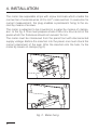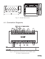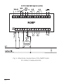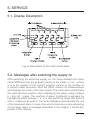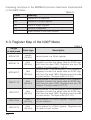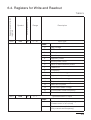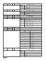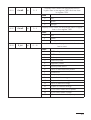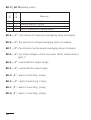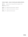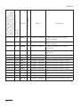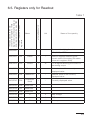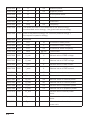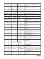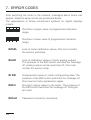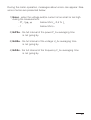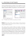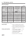
1
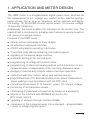
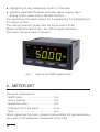
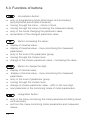
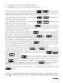
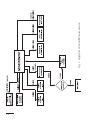
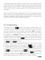
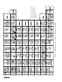
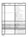
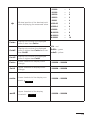
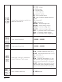
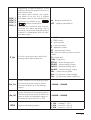
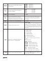
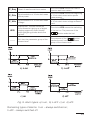
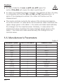
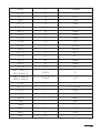
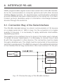
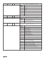
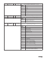
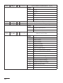
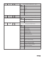
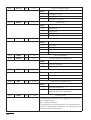
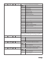
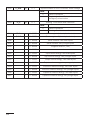
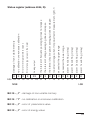
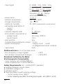
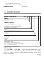
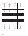
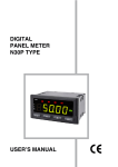
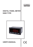
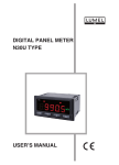
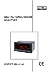
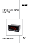
DIGITAL PANEL METER N30P TYPE USER’S MANUAL Contents 1. APPLICATION and METER DESIGN...........................................5 2. METER SET...................................................................................6 3. BASIC REQUIREMENTS, OPERATIONAL SAFETY .................7 4. INSTALLATION.............................................................................8 5. SERVICE.....................................................................................11 6. RS-485 INTERFACE ..................................................................26 7. ERROR CODES..........................................................................46 8. UPDATING OF SOFTWARE.......................................................48 9. TECHNICAL DATA.....................................................................50 10. ORDER CODES..........................................................................53 11. MAINTENANCE AND GUARANTEE..........................................55 1. APPLICATION AND METER DESIGN The N30P meter is a programmable digital panel meter destined for the measurement of a.c. voltage, a.c. current, active, reactive and apparent power, cos ϕ, tg ϕ, ϕ, frequency, active, reactive and apparent energy, 15, 30 and 60 minutes’ active power, 10 minutes’ voltage, 10 seconds’ frequency. Additionally, the meter enables the indication of the current time. The readout field is composed of a display which allows to expose results in red, green and orange colours. Features of the N30P meter: l display colour individually in three ranges, l thresholds of displayed overflows, l 2 NOC relay alarms operating in 6 modes, l 2 switched relay alarms operating in 6 modes (option), l signaling of measuring range overflow, l automatic setting of the decimal point, l programming of voltage and current ratios, l programming of alarm and analog outputs with the reaction on any measured value, independently of the currently displayed value, l storage of maximal and minimal values of all input quantities, l reset of all watt-hour meters: active and reactive energy, l programmed kind of 15, 30 or 60 minutes’ active power measurement: mean walking or synchronization with the RTC clock, l manual synchronization of 15 minutes” power, 10 minutes’ voltage, l monitoring of set parameter values, l interlocking of parameter introduction by means of a password, l service of the interface with MODBUS protocol in the RTU mode (option), l updating of software through interface RS485, l conversion of the measured value into a standard – programmable current or voltage signal (option), l highlighting of any measuring unit acc. to the order, galvanic separation between terminals: alarm, supply, input, analog output, pulse output, RS-485 interface. l The switching of the alarm output on, is signaled by the highlighting of the output number. The casing protection grade from the frontal side is IP 65. Meter overall dimensions: 96 ´ 48 ´ 93 mm (with terminals). The meter casing is made of plastics. Fig. 1 View of the N30P digital meter 2. METER SET The set is composed of: - N30P meter.......................................... 1 pc - User’s manual...................................... 1 pc - Guarantee card.................................... 1 pc - Clamps to fix in the panel.................... 4 pcs - Seal...................................................... 1 pc When unpacking the meter, please check whether the type and execution code on the data plate correspond to the order. 3. BASIC REQUIREMENTS, OPERATIONAL SAFETY In the safety service scope, the meter meets the requirements of the EN 61010-1 standard. Observations concerning the operational safety · All operations concerning transport, installation, and commissioning as well as maintenance, must be carried out by qualified, skilled personnel, and national regulations for the prevention of accidents must be observed. · The programming of N30P meter parameters must be carried out after disconnecting measuring circuits · Before switching the meter on, one must check the correctness of connections to the network. · Do not connect the meter to the network through an autotransformer. · Before removing the meter housing, one must switch the supply off and disconnect measuring circuits. · The removal of the meter housing during the guarantee contract period may cause its cancellation. · The meter fulfills requirements related to electromagnetic compatibility in the industrial environment · When connecting the supply, one must remember that a switch or a circuit-breaker should be installed in the building. This switch should be located near the device, easy accessible by the operator, and suitably marked as an element switching the meter off. · Non-authorized removal of the housing, inappropriate use, incorrect installation or operation, creates the risk of injury to personnel or meter damage. For more detailed information, please study the User’s Manual. 4. INSTALLATION The meter has separable strips with screw terminals which enable the connection of external wires of 2.5 mm 2 cross-section. In execution for current measurement, the plug enables a permanent fixing to the socket by means of screws. The meter is adapted to be mounted in a panel by means of clamps, acc. to the fig. 2. One must prepare a hole of 92 +0.6 ´ 45 +0.6 mm in the panel which the thickness should not exceed 15 mm. The meter must be introduced from the panel front with disconnected supply voltage. Before the insertion into the panel, one must check the correct placement of the seal. After the insertion into the hole, fix the meter by means of clamps (fig.2). Fig. 2. Meter fixing Fig. 3. Overall dimensions 4.1. Connection Diagrams Fig. 4. Electrical connections of the N30P meter for direct measurements Fig. 5. Electrical connections of the N30P meter for indirect measurements 10 5. SERVICE 5.1. Display Description Fig. 6. Description of the meter frontal plate 5.2. Messages after switching the supply on After switching the switching supply on, the meter displays the meter name N30P and next the program version in the shape „r x.xx” – where x.xx is the number of the current program version or the number of a custom-made execution. Next the meter carries out measurements and displays the value of the input signal. The meter sets automatically the decimal point position when displaying the value, using prefixes k – kilo, M – mega. The overflow of alarm thresholds is signaled by highlighting alarm indexes 1, 2, 3, 4 and switching relays (for alarm 3 and 4 –relays are as option). The meter highlights automatically the unit of the measured value. In case of an error occurrence or any exceeding of the range value, a message described in the chapter 7 will be displayed on the display. 11 5.3. Functions of buttons - Acceptation button: ⇒ ⇒ ⇒ ⇒ ⇒ entry in programming mode (hold down ca 3 secondes) (przytrzymanie przez około 3 sekund), moving through the menu – choice of level, moving through the menu monitoring the measured values, entry in the mode changing the parameter value, acceptation of the changed parameter value. ⇒ ⇒ ⇒ ⇒ ⇒ display of maximal value, display of maximal value – menu monitoring the measured parameters, entry in the level of the parameter group, moving through the chosen level, change of the chosen parameter value – increasing the value. ⇒ ⇒ ⇒ ⇒ ⇒ ⇒ display of minimal value, display of minimal value – menu monitoring the measured parameters, entry in the level of parameter group, moving through the chosen level, change of chosen parameter value – shift on the next digit, next parameter in the monitoring mode of meter parameters. - Button increasing the value: - Button to change the digit: - resignation button: ⇒ ⇒ 12 entry in the menu monitoring the meter parameters (holding down ca 3 seconds), exit from the menu monitoring meter parameters and measured values, ⇒ resignation of the parameter change, ⇒ absolute exit from the programming mode. The pressure of the button combination and holding down them ca 3 seconds causes the reset of alarm signaling. This operation acts only when the support function is switched on. The pressure of the button combination causes the erasing of all minimal values. The pressure of the button combination causes the erasing of all maximal values. The pressure and holding down the button ca 3 seconds causes the entry to the programming matrix. The programming matrix is protected by the safety code. The pressure and holding down the button 3 seconds causes the entry to the menu monitoring meter parameters. One must move through the monitoring menu by means of and buttons. In this menu all programmable meter parameters are only accessible for readout, excepting service parameters. The exit for the monitoring menu is carried out by means of the button. In the monitoring menu, parameter symbols are displayed alternately with their values. The service algorithm of the meter is presented on the fig. 7. The pressure and holding down and buttons, ca 3 seconds, causes the entry to the menu monitoring measured values. One must move through the monitoring menu by means of , and buttons. The pressure of the button causes the display of successive symbol of measured value alternately with the value. The pressure of the button causes the display of minimal value of the currently displayed value, however the pressure of the button causes the display of the maximal value of the currently displayed value. The exit from the monitoring menu is carried out by means of the button. In case of capacitive load when the reactive power is displayed a symbol ( ) showing type of load is highlighted. Individual measurements 13 14 Fig. 7. Algorythm of the N30P meter service of averaged values are performed, respectively: the averaged power every 15 seconds, the averaged voltage every 5 seconds and the averaged frequency every second. In case of averaged power, at selected 15 min, 30 min, 60 min respectively 60, 120 or 240 measurements are avereged. When you start the meter or erasing power, the first everaged value of active power will be calculated after 15 seconds after the meter switching on or deletions. Until the samples are gathered, average values are calculated from samples already measured. 5.4. Programming The pressure of the button and holding it down through ca 3 seconds causes the entry to the programming matrix. If the entry is protected by a password, then the safety code symbol SEC is displayed alternately with the set value 0. The write of the correct code causes the display of the ErCod inscription. The matrix of transitions to the programming mode is presented on the fig. 8. The choice of the level is made by means of the button , however the entry and moving through the parameters of the chosen level is carried out by means of the and buttons, Parameter symbols are displayed alternately with their current values. In order to change values, one must use the button. To resign fo the parameter change, one must press the button. In order to exit from the chosen level, one must chose the ----- symbol and press the buton or press the button . To exit from the programming matrix, one must press several times the button till the appearance of the inscription End and after ca 3 seconds, the meter enters automatically in the measurement of the input quantity. 15 16 Fig. 8. Transition matrix in the programming mode * Do not occur in the execution without additional output plate. Value Change Way of the Chosen Parameter Change of Integral Values In order to increase the value of the chosen parameter, one must press the buton. The single pressure of the button, causes the increase of the value of 1. The holding down of the button causes a continuous increase of the value on the given digit. The increase of value when displaying the digit 9 causes the setting of 0 on this digit. The change of the digit follows after pressing the button. In order to accept the set parameter, one must hold down the button. Then, the saving of the parameter follows and the display of its symbol alternately with the new value. The pressure of the button during the change of the parameter value will cause the resignation of the write. Changing of Values The change is carried out in three stages (the transition to the next stage follows after pressing the button: 1) setting the value from the range -19999M...99999M, similarly as for integral values; 2) setting of the decimal point position (00000., 0000.0, 000.00, 00.000, 0.0000); the button shifts the decimal point to the left, however the button shifts the decimal point to the right; 3) choice of the prefix: lack, k, M; the button switches the next prefix; the chosen prefix is displayed in orange. The pressure of the button during the change of the parameter value will cause the resignation of the saving. 17 Table 1 Parameter symbol Description Range of changes U – RMS voltage I – RMS current P – active power q – reactive power S – apparent power PF – factor of active power tG – ratio of reactive power to the active power tYP Choice of the displayed quantity FI – phase shift FrEq - frequency EPPoS – active energy input EPneg – active energy output EqPoS – reactive energy input Eqneg – reactive energy output PAv – mean active power UAv – 10 minutes’ mean voltage FAv – 10 seconds’ mean frequency HoUr – current time SYn Type of input synchronization U – synchronization with voltage (measurement of all values) I – synchronization with current (only measurement of current and frequency) rAnU Choice of voltage range 100U – range 100 V 400U – range 400 V rAnI Choice of current range 1A – range 1 A 5A – range 5 A trU trI Choice of voltage ratio 1...4000.0 Choice of current ratio 1...10000 Synchronization of averaged active power 15 – 15 minutes walking window c_15 – measurement every 15 minutes synchronized with the clock c_30 – measurement every 30 minutes synchronized with the clock c_15 – measurement every 60 minutes synchronized with the clock PAv S 18 dp Minimal position of the decimal point when displaying the measured value. 0.0000 – 0 00.000 – 1 000.00 – 2 0000.0 – 3 00000 – 4 k 000.00 – 5 k 0000.0 – 6 k 00000 – 7 M 000.00 – 8 M 0000.0 – 9 M 00000 – 10 CoLdo Display colour when the displayed value is less than CoLLo CoLbE Display colour when the displayed value is higher than CoLLo and less than CoLHI CoLUP Display colour when the displayed value is higher than CoLHI CoLLo Lower threshold of display colour change -19999M ... 99999M CoLHI Upper threshold of display colour change -19999M ... 99999M ovrLo ovrHI Lower threshold of the display constraint ----- ” Upper threshold of the display constraint ----- ” rEd – red GrEEn – green orAnG – yellow -19999M ... 99999M -19999M ... 99999M 19 Kind of input value type, which the alarm has to react on. U – RMS voltage I – RMS current P – active power q – reactive power S – apparent power PF – active power factor tG – ratio of reactive power to active power FI – phase shift FrEq - frequency EPPoS – active energy input EPnEG – active energy output EqPoS – reactive energy input EqnEG – reactive energy output PAv – 15 minutes’ mean active power UAv – 10 minutes’ mean voltage FAv – 10 seconds’ mean frequency. Lower alarm threshold. -19999M ... 99999M Upper alarm threshold. -19999M ... 99999M tYP 1 tYP 2 tYP 3 tYP 4 Alarm type. The fig. 9. presents a graphic display of alarm types. n-on – normal (transition from 0 to 1), n-oFF – normal (transition from 1 to 0), on - switched on, oFF – switched off, H-on – manually switched on; till the time of alarm type change, the alarm output remains switched on for good. H-oFF – Manually switched off; till the time of alarm type change, the alarm output remains switched off for good. dLY_1 dLY_2 dLY_3 dLY_4 Delay of alarm switching. 0...900 seconds P_A1 P_A2 P_A3 P_A4 PrL 1 PrL 2 PrL 3 PrL 4 PrH 1 PrH 2 PrH 3 PrH 4 20 LEd_1 LEd_2 LEd_3 LEd_4 Supporting of alarm signaling. In the situation when the support function is switched on after the alarm state retreat, the signaling diode is not put out. It signals the alarm state till the moment of its extinction by means of the button combination. on – support switched on oFF – support switched off The function concerns only and exclusively the alarm signaling, that is the relay contacts will operate without support in compliance with the chosen alarm type. Kind of input value type, which the analog output has to react on. U – RMS voltage I – RMS current P – active power q – reactive power S – apparent power PF – active power factor tG – ratio of reactive power to active power FI – phase shift FrEq - frequency EPPoS – active energy input EPnEG – active energy output EqPoS – reactive energy input EqnEG – reactive energy output PAv – mean active power UAv – 10 minutes’ mean voltage FAv – 10 seconds’ mean frequency. An_Lo Lower threshold of the analog output. One must give the value for which we want to obtain 0 on the analog output. -19999M ... 99999M An_HI Upper threshold of the analog output. One must give the value for which we want to obtain the maximal signal on the analog output (20 mA or 10V). -19999M ... 99999M tYPA Type of the analog output 0_10U – voltage 0...10 V 0_20A – current 0...20 mA 4_20A – current 4...20 mA P_An 21 bAUd Baud rate of the RS-485 interface transmission. 4800 – 4800 bit/s 9600 – 9600 bit/s 19200 – 19200 bit/s 38400 – 38400 bit/s Prot Kind of transmission through the RS-485 interface. r8n2 r8E1 r8o1 r8n1 Addr Device address 1...247 SEt Write of manufacturer settings. Parameter values set by the manufacturer are presented in the table 2. The setting of the value YES causes the saving of standard parameters in the meter. SEC Introduction of a new password. 0...60000 Setting of the current time. 0,00...23,59 The introduction of an erroneous time causes at the acceptation, the setting 23, however the introduction of erroneous minutes will cause the setting of the value 59. UnIt Selection of measured value for which the unit is highlighted. U – RMS voltage I – RMS current P – active power q – reactive power S – apparent power PF – active power factor tG – ratio of reactive power to active power FI – phase shift FrEq - frequency EPPoS – active energy input EPnEG – active energy output EqPoS – reactive energy input EqnEG – reactive energy output PAv – mean active power UAv – 10 minutes’ mean voltage FAv – 10 seconds’ mean frequency. C_EnP Reset of active watt-hour meters The choice YES causes the reset of active watt-hour meters HoUr 22 – – – – RTU 8N2 RTU 8E1 RTU 8O1 RTU 8N1 C_Enq Reset of reactive watt-hour meters C_PAv Synchronization of 15 minutes’ mean active power C_UAv Synchronization of 10 minutes’ mean voltage The choice YES causes the reset of reactive watt-hour meters. The choice YES causes the beginning of 15 minutes’ mean active power measurement. The choice YES causes the beginning of 10 minutes’ mean voltage measurement. tESt Display test. The test consist on the successive lighting up of digital display segments. Alarm diodes and highlighting diodes should be lighted. The choice YES causes the switching of the test on. The pressure of the button ends the test. ----- Exit from the parameter group of the chosen level. The pressure of the button causes the exit from the parameter group of the chosen level. a) n-on b) n-off c) on d) off Fig. 9. Alarm types: a) n-on, b) n-oFF c) on d) oFF. Remaining types of alarms: h-on – always switched on; h-oFF – always switched off. 23 Caution! l In case of alarms of n-on, n-oFF, on, oFF types the write of PrL>PrH will cause the alarm switching off. l In case of a measuring range overflow, the reaction of the n-th relay is compatible with written PrL_n, PrH_n, tYP_n parameters. In spite of the displayed overflow, the meter still carries out the measurement. l The meter controls currently the value of the introduced parameter at the moment. In case when the introduced value overflows the upper range given in the table 1, the meter will make automatically the change into the maximal value. Similarly, in case when the introduced value overflows the lower change range given in the table 1, the meter will make automatically the change into the minimal value. 5.5. Manufacturer’s Parameters Table 2 Standard value Parameter symbol Level in the matrix tYP 1 P SYn 1 U rAnU 1 400 U rAnI 1 5A trU 1 1,0 trI 1 1 PAv S 1 15 0.0000 (0) 24 dP 2 CoLdo 2 GrEEn CoLbE 2 orAnG CoLUP 2 rEd CoLLo 2 920 CoLHI 2 1150 ovrLo 2 99999M ovrHI 2 P_A 1 3 -19999M P PrL_1 3 920 PrH_1 3 1150 tYP_1, 3 n-on P_A 2 4 I PrL_2 4 4.000 PrH_2 4 5.000 tYP_2, 4 n-on P_A3 5 U PrL_3 5 200.00 PrH_3 5 250.00 tYP_3, 5 oFF P_A 4 6 PF PrL_4 6 0.800 PrH_4 6 0.999 tYP_4 6 oFF dLY_1, dLY_2, dLY_3, dLY_4 3,4,5,6 0 LEd_1, LEd_2, LEd_3, LEd_4 3,4,5,6 off P_An 7 I tYP_A 7 0...20 mA An_Lo 7 0.000 An_HI 7 5.000 bAUd 7 9600 Prot 7 r8n2 Addr 7 1 SEC 8 0 HoUr 8 0.00 Unit 8 P 25 6. INTERFACE RS-485 N30P programmable digital meters have serial links in RS-485 standards for the communication in computer systems and with other devices fulfilling Master function. An asynchronous communication character protocol MODBUS has been implemented on the serial link. The transmission protocol describes ways of information interchange between devices through the serial link. 6.1. Connection Way of the Serial Interface The RS-485 standard allows to a direct communication of 32 devices on a single serial link of 1200 m long. For the connection of a higher quantity of devices, it is necessary to apply additional intermediateseparating systems. The leading of the interface line out is given in the meter user’s manual. To obtain a correct transmission, it is necessary to connect lines A and B with their equivalent in other devices. The connection must be made through a shielded wire. The shield must be connected to the protection terminal in a single point. The GND line serves to the additional protection of the interface line at long connections. One must connect it to the pro- Fig. 10. Connection way of the RS-485 interface 26 tection terminal (it is not necessary for a correct interface work). To obtain the connection with a computer of IBM PC class, a RS-485 card or a RS-232/RS-485 converter is indispensable. The connection way of devices is shown on the fig. 10 The designation of transmission lines for the card in the PC komputer depends on the card producer. 6.2. Description of the MODBUS Protocol Implementation. The implemented protocol is in accordance with the PI-MBUS-300 Rev G of Modicon Company specification. Set of the serial link parameters of meters in MODBUS protocol: • meter address 1...247, • baud rate 4800, 9600, 19200, 38400 bit/s, • work modes RTU, • information unit RTU: 8N2, 8E1, 8O1, 8N1, • maximal response time 1000 ms • The maximum number of read records in one query: - 60 registers – 4 bytes, - 120 registers – 2 bytes. Parameter configuration of the serial link is described in the further part of the user’s manual. It consists on the settlement of the baud rate (bAUd parametr), device address (Addr parameter), and the type of the configuration unit (Mode parameter) Notice: Each meter connected to the communication network must have : • unique address, different from addresses of other devices connected to the network, • identical baud rate and type of information unit. 27 Following functions of the MODBUS protocol hale been implemented in the N30P meter: Table 3 Code Meaning 03 Readout of n-registers 04 Readout of single register 06 Write of single register 16 Write of n-registers 17 Identification of the slave device. 6.3. Register Map of the N30P Meter Table 4 Range of addresses Value type 4000-4100 integer (16 bits) 6000-6113 float (32 bits) 6200-6227 float (32 bits) 7000-7113 float (32 bits) Value placed in two successive 16-bit registers. Registers include the same data as 32-bit register from the area 7500. Registers are only for readout. The byte order (3-2-1-0). 7200-7227 float (32 bits) Value placed in two successive 16-bit registers. Registers include the same data as 32-bit register from the area 7600. Registers can be read out and written. The byte order (3-2-1-0). 7500-7556 float (32 bits) Value placed in a 32-bit register. Registers are only for readout. 7600-7613 float (32 bits) Value placed in a 32-bit register. Registers can be read out and written. 28 Description Value placed in a 16-bit register. Value placed in two successive 16-bit registers. Registers include the same data as 32-bit register from the area 7500. Registers are only for readout. The byte order (1-0-3-2) Value placed in two successive 16-bit registers. Registers include the same data as 32-bit register from the area 7600. Registers can be read out and written. The byte order (1-0-3-2) 6.4. Registers for Write and Readout 4000 4001 Symbol tYP SYn Write (w)/Readout (r) Values placed In 16-bit registers Table 5 w/r w/r Range Description 0...16 Input type Value 0 RMS voltage 1 RMS current 2 Active power 3 Reactive power 4 Apparent power 5 Active power factor 6 Ratio of reactive/active power 7 Phase shift 8 Frequency 9 Input of active energy 10 Output of active energy 11 Input of reactive energy 12 Output of reactive energy 13 Mean active power 14 10 minutes’ mean voltage 15 10 secondes’ mean frequency 16 Current time 0...1 Synchronization of input Value 0 Synchronization with the voltage (measurement of all values) 1 Synchronization with the current (only current and frequency) 29 4002 rAn U w/r 0...1 Voltage input range Value 4003 rAn I w/r 0 Range 100 V 1 Range 400 V 0...1 Current input range Value 0 4004 4005 4006 4007 4008 4009 4010 tr u tr I PAv S w/r w/r w/r Reserved Reserved w/r dP CoLdo w/r 1...40000 1...10000 0...1 Range 1 A 1 Range 5 A Voltage ratio *0.1 Current ratio Synchronization of averaged active power Value 0 Walking window 1 Measurement every 15 minutes synchronized with the internal clock 2 Measurement every 30 minutes synchronized with the internal clock Measurement every 60 minutes synchronized 3 with the internal clock 0...10 Minimal decimal point Value 0 0.0000 1 00.000 2 000.00 3 0000.0 4 00000 5 k 000.00 6 k 0000.0 7 k 00000 8 M 000.00 9 M 0000.0 10 M 00000 Display colour when the displayed value is less than in the register 7600 0...2 Value 30 0 red 1 green 2 orange 4011 CoLbE w/r Display colour when the displayed value is higher than in the register 7600 and less than in register 7601. 0...2 Value 4012 CoLuP w/r 0 red 1 green 2 orange Display colour when the displayed value is higher than in the register 7601 0...2 Value 4013 P_A1 w/r 0 red 1 green 2 orange Kind of the input quantity type on which the alarm 1 has to react. 0...15 Value 0 RMS voltage 1 RMS current 2 Active power 3 Reactive power 4 Apparent power 5 Active power factor 6 Ratio of reactive/active power 7 Phase shift 8 Frequency 9 Input of active energy 10 Output of active energy 11 Input of reactive energy 12 Output of reactive energy 13 15 minutes’ mean active power 14 10 minutes’ mean voltage 15 10 secondes’ mean frequency 31 4014 tYP_1 w/r 0...5 Type of alarm 1 (description – fig. 6) Value 4015 dLY_1 w/r 0...120 4016 LEd_1 w/r 0...1 0 n-on 1 n-oFF 2 on 3 oFF 4 H-on 5 H-oFF Delay of alarm 1 (in seconds) Support of alarm 1 signaling Value 4017 32 P_A2 w/r 0 Support switched off 1 Support switched on Kind of the input quantity type on which the alarm 2 has to react. 0...15 Value 0 RMS voltage 1 RMS current 2 Active power 3 Reactive power 4 Apparent power 5 Active power factor 6 Ratio of reactive/active power 7 Phase shift 8 Frequency 9 Input of active energy 10 Output of active energy 11 Input of reactive energy 12 Output of reactive energy 13 15 minutes’ mean active power 14 10 minutes’ mean voltage 15 10 seconds’ mean frequency 4018 tYP_2 w/r 0...5 Type of alarm 2 (description – fig. 6) Value 4019 dLY_2 w/r 0...120 4020 LEd_2 w/r 0...1 0 n-on 1 n-oFF 2 on 3 oFF 4 H-on 5 H-oFF Delay of alarm 2 (in seconds) Support of alarm 2 signaling Value 4021 P_A3 w/r 0 Support switched off 1 Support switched on Kind of the input quantity type on which the alarm 3 has to react. 0...15 Value 0 RMS voltage 1 RMS current 2 Active power 3 Reactive power 4 Apparent power 5 Active power factor 6 Ratio of reactive/active power 7 Phase shift 8 Frequency 9 Input of active energy 10 Output of active energy 11 Input of reactive energy 12 Output of reactive energy 13 15 minutes’ mean active power 14 10 minutes’ mean voltage 15 10 seconds’ mean frequency 33 4022 tYP_3 w/r 0...5 Type of alarmu 3 (description – fig. 6) Value 4023 dLY_3 w/r 0...120 4024 LEd_3 w/r 0...1 0 n-on 1 n-oFF 2 on 3 oFF 4 H-on 5 H-oFF Delay of alarm 3 (in seconds) Support of alarm 3 signaling Value 4025 34 P_A4 w/r 0 Support switched off 1 Suport switched on Kind of the input quantity type on which the alarm 4 has to react. 0...15 Value 0 RMS voltage 1 RMS current 2 Active power 3 Reactive power 4 Apparent power 5 Active power factor 6 Ratio of reactive/active power 7 Phase shift 8 Frequency 9 Input of active energy 10 Output of active energy 11 Input of reactive energy 12 Output of reactive energy 13 Mean active power 14 10 minutes’ mean voltage 15 10 seconds’ mean frequency 4026 tYP_4 w/r 0...5 Type of alarm 4 (description – fig. 6) Value 4027 dLY_4 w/r 0...120 4028 LEd_4 w/r 0...1 0 n-on 1 n-oFF 2 on 3 oFF 4 H-on 5 H-oFF Delay of alarm 4 (in seconds) Support of alarm 4 signaling Value 4029 P_An w/r 0 Support switched off 1 Support switched on Kind of the input quantity type on which the analog output has to react. 0...15 Value 0 RMS voltage 1 RMS current 2 Active power 3 Reactive power 4 Apparent power 5 Active power factor 6 Ratio of reactive/active power 7 Phase shift 8 Frequency 9 Input of active energy 10 Output of active energy 11 Input of reactive energy 12 Output of reactive energy 13 Mean active power 14 10 minutes’ mean voltage 15 10 seconds’ mean frequency 35 4030 tYP_A w/r 0...2 Type of analog output Value 4031 bAUd w/r 0 1 2 0...3 Voltage 0...10 V Current 0...20 mA Current 4...20 mA Baud rate Value 4032 Prot w/r 0 1 2 3 0...3 4800 bit/s 9600 bit/s 19200 bit/s 38400 bit/s Baud rate Value 0 1 2 3 RTU 8N2 RTU 8E1 RTU 8O1 RTU 8N1 4033 Addr w/r 0...247 Device address 4034 sAvE w/r 0...1 Update display parameters Value 4035 SEt w/r 0 1 0...1 without changes update Write of standard parameters Value 4036 SEC w/r 0 1 0...60000 without changes set standard parameters Password for parameters Value 0 without password 1...60000 entry in parameters preceded by a request about the password 4037 HoUr w/r 0...2359 Current time This parameter occurs in the ggmm format, where: gg - means hours, mm – means minutek. The introduction o a wrong hour will cause the setting 23, however the introduction of wrong minutes will generate the setting 59. 36 4038 Unit w/r 0...16 Switch on and off the unit display Value 0 RMS voltage 1 RMS current 2 Active power 3 Reactive power 4 Apparent power 5 Active power factor 6 Ratio of reactive/active power 7 Phase shift 8 Frequency 9 active energy 10 reactive energy 11 apparent energy 12 Output of reactive energy 13 Mean active power 14 10 minutes’ mean voltage 15 10 secondes’ mean frequency 16 Current time 17 Switched off for good. The unit is displayed when the value In the register 4000 is equal to the value In the register 4038 4039 C_EnP w/r 0...1 Reset of active watt-hour meters Value 4040 C_Enq w/r 0 1 0...1 Lack of operation Reset of active watt-hour meters Reset of reactive watt-hour meters Value 4041 C_PAv w/r 0 1 0...1 Lack of operation Reset of reactive watt-hour meters Synchronization of mean power Value 0 1 Lack of operation Beginning of the mean power synchronization 37 4042 C_UAv w/r 0...1 Synchronization of the 10 minutes’ mean voltage Value 0 1 4043 LI_0 w/r 0...1 Lack of operation Beginning of the 10 minutes’ mean voltage synchronization Erasing of minimum and maximum Value 0 1 Lack of operation Erasing of minimum and maximum 4044 StAt r 0...65536 Status register (description below) 4045 StAt2 r 0...65536 Status register 2 (description below) 4046 r 0...65536 Serial number: two odler bytes 4047 r 0...65536 Serial number: two younger bytes 4048 r 0...65536 Program version (*100) 4049 r 0...65536 reserved 4050 r 0...15258 Input active energy, two older bytes 4051 r 0...65536 Input active energy, two younger bytes 4052 r 0...15258 Output active energy, two older bytes 4053 r 0...65536 Output active energy, two younger bytes 4054 r 0...15258 Inductive reactive energy, two older bytes 4055 r 0...65536 Inductive reactive energy, two younger bytes 4056 r 0...15258 Capacitive reactive energy, two older bytes 4057 r 0...65536 Capacitive reactive energy, two younger bytes 38 X X X X XX bits 15 14 13 12 11 10 9 8 7 6 5 4 MSB 3 2 1 alarm 1 switching (relay) alarm 2 switching (relay) alarm 3 switching (relay) alarm 4 switching (relay) exceeded the lower range exceeded the upper range too small voltage,current for power factor measurement, tg(fi), fi the interval of active power averaging does not elapse the interval of voltage averaging does not elapse the interval of frequency averaging does not elapse Analog output Error of energy values in the meter Error of meter parameters values no calibration or erroneous calibration damage of non-volatile memory Status register (address 4044, R): X X X X X X X X X X 0 LSB Bit-15 - „1” - damage of non-volatile memory Bit-14 -”1” - no calibration or erroneous calibration Bit-13 - „1” - error of parameters value Bit-12 - „1” - error of energy value 39 Bit 11 Bit 10 Bit-11, bit 10 analog output 0 0 1 1 0 1 0 1 Meaning voltage output 0...10 V current output 0...20 mA current output 4...20 mA lack of calibration of analog output Bit-9 - „1” - the interval of frequency averaging does not elapse Bit-8 - „1”- the interval of voltage averaging does not elapse Bit-7 - „1”- the interval of active power averaging does not elapse Bit-6 - „1”- too small voltage,current for power factor measurement, tg(fi), fi Bit-5 - „1” - exceeded the upper range Bit-4 - „1” - exceeded the lower range Bit-3- „1” - alarm 4 switching (relay) Bit-2 - „1” - alarm 3 switching (relay) Bit-1- „1” - alarm 2 switching (relay) Bit-0- „1” - alarm 1 switching (relay) 40 Status 2 register – nature of reactive power (address 4045, R): Bit-15 - negative active energy difference (register 7518) Bit-14...3 - reserved Bit-2 - „1” - capacitive reactive power maximum Bit-1 - „1” - capacitive reactive power minimum Bit-0 - „1” - capacitive reactive power 41 Symbol write (w)/readout (r) The value is placed in 32-bit registers The value placed In two successive 16-bit registers. These registers include the same data as 32-bit registers from the area 7600 Table 6 Range Description 6200/7200 7600 CoLLo w/r -19999M...99999M Lower threshold of the display colour change 6202/7202 7601 CoLHI w/r -19999M...99999M Upper threshold of the display colour change 6204/7204 7602 ovrLo w/r -19999M...99999M Lower threshold of the display narrowing 6206/7206 7603 ovrHI w/r -19999M...99999M Upper threshold of the display narrowing 6208/7208 7604 PrL_1 w/r -19999M...99999M Lower threshold of alarm 1 (Aoff) 6210/7210 7605 PrH_1 w/r -19999M...99999M Upper threshold of alarm 1 (Aon) 6212/7212 7606 PrL_2 w/r -19999M...99999M Lower threshold of alarm 2 (Aoff) 6214/7214 7607 PrH_2 w/r -19999M...99999M Upper threshold of alarm 2 (Aon) 6216/7216 7608 PrL_3 w/r -19999M...99999M Lower threshold of alarm 3 (Aoff) 6218/7218 7609 PrH_3 w/r -19999M...99999M Upper threshold of alarm 3 (Aon) 6220/7220 7610 PrL_4 w/r -19999M...99999M Lower threshold of alarm 4 (Aoff) 6222/7222 7611 PrH_4 w/r -19999M...99999M Upper threshold of alarm 4 (Aon) 6224/7224 7612 An_Lo w/r -19999M...99999M Lower threshold of analog output 6226/7226 7613 An_HI w/r -19999M...99999M Upper threshold of analog output 42 6.5. Registers only for Readout 6000/7000 7500 Name Identifier write (w)/readout (r) The value is placed in 32-bit registerss The value placed In two successive 16-bit registers. These registers include the same data as 32-bit registers from the area 7500 Table 7 r Unit – Name of the quantity Constant identifying the device 179 (0xB3) - N30P 6002/7002 7501 Status r – Status is register describing the current state of the meter (the same value as in register 4044) 6004/7004 7502 Control r % It is a register defining the control of the analog output 6006/7006 7503 Minimum r – Minimal value of the currently displayed value 6008/7008 7504 Maksimum r – Maximal value of the currently displayed value 6010/7010 7505 Displayed Value r – Currently displayed value 6012/7012 7506 Reserved 6014/7014 7507 Reserved 6016/7016 7508 Reserved 6018/7018 7509 U r V RMS voltage 6020/7020 7510 I r A RMS current 6022/7022 7511 P r W Active power 43 6024/7024 7512 Q r var Reactive power 6026/7026 7513 S r VA Apparent power 6028/7028 7514 PF r 6030/7030 7515 tG r 6032/7032 7516 FI r ° Phase shift 6034/7034 7517 FrEq r Hz Frequency Active power factor Ratio of reactive/active power 6036/7036 7518 The absolute value of the difference of the active energy: the absorbed active energy – the given back active energy 6038/7038 7519 Sum of the passive energy: the inductive passive energy + the capacitive passive energy 6040/7040 7520 Reserved 6042/7042 7521 PAv r W 15 minutes’ mean power 6044/7044 7522 UAv r V 10 minutes’ mean voltage 6046/7046 7523 FAv r Hz 6048/7048 7524 HoUr r gg,mm 6050/7050 7525 U_min r V Minimal value of RMS voltage 6052/7052 7526 U_max r V Maximal value of RMS voltage 6054/7054 7527 I_min r A Minimal value of RMS current 6056/7056 7528 I_max r A Maximal value of RMS current 6058/7058 7529 P_min r W Minimal value of active power 6060/7060 7530 P_max r W Maximal value of active power 6062/7062 7531 Q_min r var Minimal value of reactive power 6064/7064 7532 Q_max r var Maximal value of reactive power 6066/7066 7533 S_min r VA Minimal value of apparent power 6068/7068 7534 S_max r VA Maximal value of apparent power 6070/7070 7535 PF_min r Minimal value of active power factor 6072/7072 7536 PF_max r Maximal value of active power factor 6074/7074 7537 tG_min r Minimal value of reactive/active power ratio 44 10 seconds’ mean frequency Current time 6076/7076 7538 tG_max r 6078/7078 7539 FI_min r 6080/7080 7540 FI_max 6082/7082 7541 FrEq_min 6084/7084 7542 Maximal value of reactive/active power ratio ° Minimal value of phase shift r ° Maximal value of phase shift r Hz Minimal value of frequency FrEq_max r Hz Maximal value of frequency 6086/7086 7543 PAv_min r W Minimal value of mean active power 6088/7088 7544 PAv_max r W Maximal value of mean active power 6090/7090 7545 UAv_min r V Minimal value of 10 minutes’ mean voltage 6092/7092 7546 UAv_max r V Maximal value of 10 minutes’ mean voltage 6094/7094 7547 FAv_min r Hz Minimal value of 10 seconds’ mean frequency 6096/7096 7548 FAv_max r Hz Maximal value of 10 seconds’ mean frequency 6098/7098 7549 EP_PoS1 r 100MWh 6100/7100 7550 EP_PoS2 r kWh 6102/7102 7551 EP_nEG1 r 100MWh 6104/7104 7552 EP_nEG2 r kWh 6106/7106 7553 Eq_PoS1 o 100Mvarh 6108/7108 7554 Eq_PoS2 o kvarh 6110/7110 7555 Eq_nEG1 o 100Mvarh 6112/7112 7556 Eq_nEG2 o kvarh Active energy input (the counter of turning the register 7550 is reset every 9999999.9 kWh) Active energy input (modulo 100000.0) Active energy output (the counter of turning the register 7552 is reset every 9999999.9 kWh) Active energy output (modulo 100000.0) Reactive energy input (the counter of turning the register 7554 is reset every 9999999.9 kVarh) Reactive energy input (modulo 100000.0) Reactive energy output (turning counter of the register 7556 is reset every 9999999.9 kVarh) Reactive energy output (modulo 100000.0) 45 7. ERROR CODES After switching the meter to the network, messages about errors can appear. Reasons about errors are presented below. The appearance of below mentionned symbols on digital displays means: Overflow of upper value of programmed indication range. Overflow of lower value of programmed indication range. ErCAL Loss of meter calibration values. One must contact the service workshop. EroUt Loss of calibration values of meter analog outputs. The pressure of the ESC button switches the message off, analog outputs remain switched off. One must contact the service shop. Er EE Innapropriate values in meter configurating data. The pressure of the ESC button switched the message off. One must set meter parameters again. ErEnr Incorrect energy values in the meter. The pressure of the ESC button switched the message off. Energies are reset. ErCod Password incorrectly introduced. 46 During the meter operation, messages about errors can appear. Reasons of errors are presented below: 1) Erovr - when the voltage and/or current is too small or too high during the measurement: - Pf i , tgj i , j below 5% U n, 0,5 % In - f below 5% U n 2) ErPAv - the full interval of the power P_Av averaging time is not going by. 3) ErUAv - the full interval of the voltage U_Av averaging time is not going by. 4) ErFAv - the full interval of the frequency F_Av averaging time is not going by. 47 8. Updating of software Function enabling updating of software from the computer of the PC with software LPCon was implementation in meter N30P in the realization with the interface RS485. The connected to the computer convertor RS485 is required on USB to the updating, e.g.: the convertor PD10. a) b) Fig. 11. Program view: a) LPCon, b) updating of software Warning! Before doing update, currently settings of meter should be saved by program LPCon, because when software is updated default settings of meter are restored. After starting LPCon’s software COM port, baudrate, transmission mode and adress should be set. It can be done in Options. Then, N30P meter should be selected from Device. Push icon Load to read and save current settings. Open window Lumel Updater (LU) – figure 14b from Updating->Updating of devices firmware. Push Connect. Update progress is shown in Messages section. Text Port opened appear after correctly opened port. Putting meter in update’s mode can be done in two ways: remote from LU (with settings from LPCon – port, baudrate, transmission mode and adress) or by turning power on while button 48 pressed. AL1 led signals that device is ready for update. LU will show message „Device found” with name and current version ... of firmware. Using button a valid file should be selected. If the file is correct, message File opened will show. Send button should be pressed. If firmware update is successful device starts normal operation and message Done and update duration will show. Close LU and go to Restoration of manufacturer’s parameters. Select checkbox and press Apply button. Next press Send button to restore previously read parameters. Current firmware version can be checked when meter is power on. Warning! Power loss during firmware update could result permanent meter damage! 49 9. TECHNICAL DATA Measuring Ranges Table 8 Measured value Current Voltage Indication range 1A 0.000...12 kA 5 A 0.000... 60 kA L-N 100 V 0.0...0.48 MV 400 V 0.0 ...1.92 MV Measuring range Basic error 0.005...1.200 A~ 0.025...6.000 A~ ±0.2% 5...120 V 20...480 V ±0.2% 45.00...100.00 Hz 45.0...66.0...100 Hz ±0.2% -19999... 99999 MW -2.88 kW...1.40 W...2.88 kW ±0.5% Reactive power -19999 Mvar...0.00 ...99999 Mvar -2.88 kvar...1.40 var...2.88 kvar ±0.5% Apparent power 0.00...99999 MVA 1.40 VA... 2.88 kVA ±0.5% -1...0...1 -1...0...1 ±0.5% -1.2...0...1.2 -1.2...0...1.2 ±1% 0...359 0...359 ±1% Active energy 0...9 999 999.9 kWh 0...9 999 999.9 kWh ±0.5% Reactive energy 0...9 999 999.9 kvarh 0...9 999 999.9 kvarh Frequency Active power Coefficient PF Tangens j i j Current time 0.00...23.59 0.00...23.59 ±0.5% 1 second /24 h Ku – voltage transformer ratio: 0.1...4000.0 Ki – current transformer ratio: 1...10000 Relay outputs l relays, voltageless NOC contacts load-carrying capacity 250 V/0.5 A l relays, voltageless switched contacts load-carrying capacity 250 V/0.5 A (option) Analog output (option) l current programmable 0/4...20 mA load resistance 500 W l voltage programmable 0...10 V load resistance ³ 500 W l galvanically isolated l resolution 0.01% of the range 50 Serial interfaces (option) RS485: address 1...247 Mode: 8N2, 8E1, 8O1,8N1 Baud rate: 4.8, 9.6, 19.2, 38.4 kbit/s Transmission protocol: Modbus RTU Maximal time to begin a response: 1000 ms Energy pulse output (option) output of OC type, passive of A class acc.to EN 62053-31, supply voltage 18...27 V, current 10...27 mA Pulse constant of O/C type output 5000 imp./kWh, independently of Ku, Ki settings Galvanic separation between: - supply - measuring input 3.2 kV d.c. - supply - analog output 2 kV d.c. - supply - pulse output 2 kV d.c. - supply - RS485 interface 2 kV d.c. - measuring input - analog output 3.2 kV d.c. - measuring input - pulse output 3.2 kV d.c. - measuring input - RS485 interface 3.2 kV d.c. - analog input - pulse output 2 kV d.c. - analog input - RS485 interface 2 kV d.c. - alarm output - other circuits 2 kV d.c. Protection grade ensured by the casing: - from frontal side IP 65 - from rear side IP 10 Weight 0.2 kg Dimensions 96 x 48 x 93 mm Reference Conditions and Rated Operating Conditions: - supply voltage 85...253 V d.c or a.c 40...400 Hz 20...40 V d.c or a.c 40...400 Hz 51 - input signal 0...0.005...1.2I n; 0.05...1.2U n for current, voltage 0...0.1...1.2I n; 0...0.1...1.2U n; for coefficients Pf i, tj i, j frequency 45...66...100 Hz; sinusoidal (THD 8%) - power factor -1...0...1 - ambient temperature - 25...23...+55°C - storage temperature - 30...+70°C - relative air humidity 25...95% (inadmissible condensation) - admissible peak factor of: - current 2 - voltage 2 - external magnetic field 0...400 A/m - short duration overload (5 s): - voltage inputs 2Un (max.1000 V) - current inputs 10 In - work position any - minimal distance between meters 1.5 cm - power consumption: - supply circuit < 6 VA - in voltage/current circuit < 0.05 VA. - input power 6 VA Additional Errors in % of the basic error: - from frequency of input signals < 50% - from ambient temperature changes < 50%/10°C Standards Fulfilled by the Meter: Electromagnetic Compatybility: - noise immunity acc.to EN 61000-6-2 - noise emissions acc. to EN 61000-6-4 Safety Requirements: acc. to EN 61010-1 standard lisolation between circuits: basic, linstallation category III, lpollution level 2, lmaximal phase-to-earth working voltage: – for the supply circuit: 300 V – for the measuring input 600 V for analog input signals - cat. II (300 V - cat. III) 52 – for remaining circuit: 50 V above sea level < 2000 m, Preheating Time 15 minutes laltitude 10. ORDER CODES Table 9 DIGITAL PANEL METER N30P - X X XX XX X X Supply: 85... 253 V a.c./d.c. ................................................... 1 20... 40 V a.c./d.c. ..................................................... 2 Additional outputs: lack ................................................................................... 0 pulse output, RS485, analog outputs . ............................. 1 pulse output, RS485, analog outputs, switched-over relay outputs ............................................. 2 Unit: unit code number acc. to the tab. 10 . ................................... XX Version: standard ......................................................................................... 00 custom-made* ............................................................................... XX Language: Polish ...................................................................................................... P English . .................................................................................................. E other* ...................................................................................................... X Acceptance tests: without extra quality requirements ................................................................ 0 with an extra quality inspection certificate .................................................... 1 acc. to customer’s request* .......................................................................... X * - after agreeing with the manufacturer. Order example: The code: N30P - 1 0 01 00 E 0 means: programmable N30P panel digital meter, supply: 85...253 V a.c., lack of additional outputs, unit “V” acc. to the table 10, standard version, English language, without extra quality requirements, 53 Code of the highlighted unit Tablica 10 Code Unit Code Unit 00 01 02 03 04 05 06 07 08 09 10 11 12 13 14 15 16 17 18 19 20 21 22 23 24 25 26 27 28 lack of unit V A mV kV mA kA W kW MW var kvar Mvar VA kVA MVA kWh MWh kvarh Mvarh kVAh MVAh Hz kHz W kW °C °F K 29 30 31 32 33 34 35 36 37 38 39 40 41 42 43 44 45 46 47 48 49 50 51 52 53 54 55 56 % %RH pH kg bar m l s h m3 obr szt imp rsp m/s l/s obr/min rpm mm/min m/min l/min m 3/min szt/h m/h km/h m 3/h kg/h l/h XX on order1) 1) - After agreeing with the manufacturer 54 11. MAINTENANCE AND GUARANTEE The N30P digital panel meter does not require any periodical maintenance. In case of some incorrect operations: 1. From the Shipping Date, During the Period Given in the Annexed Guarantee Card One should take the meter down from the installation and return it to the Manufacturer’s Quality Control Dept. If the meter has been used in compliance with the instructions, the Manufacturer warrants to repair it free of charge. 2. After the Guarantee Period: One should turn over the meter to repair it in a certified service workshop. The disassembling of the casing causes the cancellation of the granted guarantee. Our policy is one of continuous improvement and we reserve the right to make changes in design and specifications of any products as engineering advances or necessity requires and revise the above specifications without notice. 55 N30P-09B LUMEL S.A. ul. Słubicka 1 65-022 Zielona Góra - Poland Tel.: (48-68) 45 75 100 (exchange) Fax: (48-68) 45 75 508 e-mail: [email protected] http://www.lumel.com.pl 56 Export Department: Tel.: (48-68) 45 75 302 or 304 Fax: (48-68) 325 40 91 e-mail: [email protected]