1
DIGITAL INTERCOM
USER MANUAL
1 JANUARY 2011
ASL RESERVES THE RIGHT TO ALTER SPECIFICATIONS WITHOUT
PRIOR NOTICE
HOWEVER, ALTERATIONS ARE USUALLY INCORPORATED IN THE NEXT
ISSUE OF THIS USER MANUAL
ASL INTERCOM BV
ZONNEBAAN 42
3542 EG UTRECHT
HOLLAND
WWW.ASL-INTER.COM
ASL DIGITAL USER MANUAL | 1 JANUARY 2011
1
CONTENT OF THIS USER MANUAL
CHAPTER A.
INTRODUCTION TO THE ASL DIGITAL INTERCOM NETWORK ................................................... 4
CHAPTER B.
SYSTEM FEATURES .................................................................................................................. 6
B1.
SWITCHING THE INTERCOM SYSTEM ON/OFF....................................................................................... 6
B3.
UNEXPECTED MAINS POWER LOSS ....................................................................................................... 7
B4.
POWER OVER STRINGS .......................................................................................................................... 7
B5.
LOGGING IN & OUT................................................................................................................................ 7
B6.
AUTO LOGIN .......................................................................................................................................... 8
B11
INSTALLATION ........................................................................................................................................ 9
CHAPTER C.
EQUIPMENT .......................................................................................................................... 11
C1.
DS 80 WALL BOX ................................................................................................................................. 11
C2.
DS 85 BOOSTER POWER SUPPLY / DATA REPEATER ........................................................................... 11
C3.
DS 88 HUB ........................................................................................................................................... 13
C4.
DS 4000 MASTER MATRIX / DS 4000 SLAVE MATRIX .......................................................................... 14
C4.1
INTRODUCTION ............................................................................................................................... 14
C4.2
CONTROLS & CONNECTORS ............................................................................................................. 15
C9.
DS 830 TABLETOP 8-CH SPEAKER STATION ......................................................................................... 18
C10.
DS 1630 TABLETOP 16-CH SPEAKER STATION ..................................................................................... 18
C11.
DS 2430 TABLETOP 24-CH SPEAKER STATION ..................................................................................... 18
C12.
DS 3230 TABLETOP 32-CH SPEAKER STATION ..................................................................................... 18
C13.
DS 1640 DIGITAL SPEAKER STATION / DS 2040 EXTENSION PANEL .................................................... 19
C13.1
INTRODUCTION ........................................................................................................................... 19
C13.2
CONTROLS & CONNECTORS ........................................................................................................ 20
C13.3
CONNECTING THE IS141 BEACON .............................................................................................. 24
C13.5
DASHBOARD LIGHTING & LED BRIGHTNESS .............................................................................. 24
C13.6
ASSIGNING FUNCTIONS TO FUNCTION BUTTONS ..................................................................... 25
C13.7
FUNCTIONS TO BE ASSIGNED TO THE DS 1640 FUNCTION BUTTONS ....................................... 25
C13.8
CHANGE GROUP POSITIONS AT ONES SPEAKER STATION ......................................................... 30
C13.11
CONNECTING THE DS 1640 TO THE DIGITAL NETWORK ............................................................ 31
C13.14
PTP (PERSON TO PERSON) OPERATION ..................................................................................... 33
C13.16
MENU OPERATION ..................................................................................................................... 36
C13.17
MENU ITEMS .............................................................................................................................. 37
C14.
DS 290 2-CHANNEL BELTPACK ............................................................................................................ 40
C14.1
INTRODUCTION ......................................................................................................................... 40
ASL DIGITAL USER MANUAL | 1 JANUARY 2011
2
C14.2
CONTROLS & CONNECTORS ....................................................................................................... 40
C14.4
CONNECTING THE DS 290 TO THE DIGITAL NETWORK ............................................................. 43
C14.6
LOGGING OUT ............................................................................................................................ 45
C14.7
PTP (PERSON TO PERSON) OPERATION ..................................................................................... 45
C15.9
MENU OPERATION ..................................................................................................................... 47
C14.10
MENU ITEMS .............................................................................................................................. 48
C15.
INTERFACES ......................................................................................................................................... 50
C15.1
INTRODUCTION ........................................................................................................................... 50
C15.2
DS 71 PARTY LINE INTERFACE ................................................................................................... 50
C15.2
DS 72 4-WIRE INTERFACE .......................................................................................................... 51
C15.4
DS 73 ANALOG AUDIO IN/OUT INTERFACE ............................................................................... 52
C15.5
DS 74 PAGING INTERFACE ......................................................................................................... 53
C16.
DS 700 19" BOX FOR INTERFACE MODULES ....................................................................................... 55
Chapter D.
CONFIGURATION SOFTWARE ................................................................................................ 58
D1.
INTRODUCTION ................................................................................................................................... 58
D2.
OPERATING THE CONFIGURATION SOFTWARE ................................................................................... 58
D4.
SCREENS............................................................................................................................................... 59
D4.1
LOGIN SCREEN ................................................................................................................................. 59
D4.2
EVENTS SCREEN ............................................................................................................................... 59
D4.3
EVENT FILE BROWSER SCREEN ........................................................................................................ 62
D4.4
GROUPS SCREEN ............................................................................................................................. 62
D4.5
USERS SCREEN ................................................................................................................................. 63
D4.6
ADVANCED USER STATION PROPERTIES SCREEN ............................................................................ 66
D4.7
USERS/GROUPS SCREEN .................................................................................................................. 67
D4.8
INTERFACES SCREEN ........................................................................................................................ 68
D4.10
SYSTEM SCREEN .......................................................................................................................... 70
D4.10.1
Matrix Connections sub-screen ............................................................................................. 70
D4.10.2
DSP Engine sub-screen .......................................................................................................... 71
D4.10.3
Equipment sub-screen (read only) ........................................................................................ 71
D4.10.4
IP Network sub-screen........................................................................................................... 71
D4.10.5
Computer- /Touch Screen sub-screen ................................................................................... 71
D4.10.6
Software/Firmware sub-screen ............................................................................................. 71
D4.10.7
Passwords sub-screen ........................................................................................................... 71
D4.10.8
System Time and Date sub-screen ........................................................................................ 71
D5.
CROSS LINKS BETWEEN SCREENS ........................................................................................................ 72
ASL DIGITAL USER MANUAL | 1 JANUARY 2011
3
Chapter A
INTRODUCTION TO THE ASL DIGITAL INTERCOM NETWORK
An ASL digital intercom network consists of a number of matrix units to which user stations (beltpacks
and speaker stations) are connected. Each matrix unit has 5 ‟intercom lines‟ (also called „strings‟).
Each intercom line serves a maximum of 8 user stations, so each matrix unit serves maximum 40 user
stations. A maximum of 6 matrix units can be interlinked to form an intercom network with maximum
240 user stations.
Wiring Configurations
An intercom line (string) is of the CAT-5 type and may have one of the following wiring configurations:
- STAR configuration: from an intercom out connector on a matrix unit, a cable goes to an 8outlet hub. From the 8 „intercom out‟ connectors of the hub, 8 cables go to 8 user stations.
- DAISY CHAIN configuration: from an „intercom out‟ connector on a matrix unit a cable goes to
the first user station, from that station to the next user station until a maximum of 8 user
stations are connected to one string. To enable this configuration, each user station has an
„Intercom In‟ connector and an „Intercom Link Out‟ connector.
- LINE configuration: from an „intercom out‟ connector on a matrix unit a cable goes to the first
wall box, from that box to the next wall box, up to a maximum of 8 wall boxes per string. To a
wall box only one user station may be connected (daisy chaining from a user station
connected to a wall box is not allowed).
Interface Modules
ASL offers a variety of interface modules, such as a Party Line, a 4-Wire, a Paging, an IFB, a
Telephone and an Emergency Interface.
A matrix unit has 2 slots for interface modules, so 6 linked matrix units offer slots for 12 interfaces.
Additional interface modules may be mounted in a 19” housing with 4 interface slots, the DS 700.
This unit may be connected to a string. Each additional interface takes one (1) user station position.
So in a digital intercom network with 1 matrix unit, in which for instance in total 6 interface modules are
required, one may connect maximum 36 user stations.
The DS-79 emergency interface module cannot be fitted in a DS 700 interface box; this interface can
only be fitted in the rear of a matrix unit.
ConfigurIT® software
This software allows a so-called System Administrator to configure the intercom system for various
„productions‟ (TV production, Theatre production, Life Concert, Convention, Sports event, etc.). In ASL
Digital the configurations are called „Events‟ and are stored in the 300 MB memory section of the
computer in a master matrix unit. An event may selected to be active, after which it determines the
actual functioning of all connected (logged in) user stations.
The software further allows the creating and property setting of Users and Groups, the assignment of
Users to Groups, the routing of interface modules, the routing of GPI/O connections and the
adjustment of System properties
The software can be operated either by a touch screen or by a computer monitor + mouse, to be
connected directly to the Master Matrix Unit. See chapter D “Configuration Software” for how to
connect a PA or Apple (laptop) computer
User ID’s
For each event, each user gets an ID number which refers to a user name, which may be the name of
a person (e.g. John Smith) or a job title (e.g. Stage Manager). It is also possible to refer to a location,
e.g. Dressing Room. The ID number is then rather a 'station number', but in the ConfgurIT software
still called 'ID number'.
Logging In
A user logs in by entering his ID number on his station. A user may, for each event separately, be
programmed to log in automatically after the intercom system has been switched on and the referring
event has been activated.
User Station Properties & Menu Accessibility
ASL DIGITAL USER MANUAL | 1 JANUARY 2011
4
For each event, the system administrator determines in the ConfigurIT software all settings
(properties) of each user station. A selection out of these settings may be changed by the user for his
own station by entering the menu on his station. The System Administrator may limit the access to the
menu items, per user station. When the user with limited menu access starts the login procedure, the
letters 'LMA' are shown in his display.
Groups & Channels
In the configuration software users and interfaces are assigned to one or more user groups. A 2channel user station may be assigned to 2 of these groups, a 16 channel user station may be
assigned to 16 of these groups, etc. A group may be set to be a Conference group (all users assigned
to such a group can talk and listen to each other, like in analog party line intercom or a Paging group,
an IFB („Interrupt Fold Back‟) group, or a Telephone group.
Up to 255 groups can be created. A user may be connected to maximum 36 of these groups (for this
maximum he needs to have a 36 channel station).
In the channel display(s) of a user station, the group names (8 characters in 2 rows) and the Listen
volumes are indicated (Volume bars).
Default settings
All user station, group and interface properties have a default setting. These settings are such that
they will satisfy the majority of the users. In this respect ASL Digital is a „plug & play‟ system.
PTP & Text Messaging
Besides communication via the groups, ASL Digital Intercom offers PTP communication (Person to
person, similar to a telephone call) and Text Messaging.
Monaural & Binaural
User stations come with XLR-4 connectors for headsets in monaural use. ASL can modify user
stations to be binaural, in which case the XLR-4 is replaced by an XLR-5 connector to allow „left/right‟
('split ear') use of headsets.
General Purpose Outputs and Inputs
GPO's are logical outputs which trigger functions of connected outboard devices.
GPO's may be used for triggering a red-light signal, stage effects, etc.
GPI's are logical inputs through which outboard devices or external systems trigger functions of the
intercom network and/or the (function) buttons of its user stations.
The System Administrator allocates, via the GPI/O screen of the ConfigurIT software, all GPI/O‟s
which are connected to external devices or (control) systems and routes these GPI/O‟s to or from their
required locations in the ASL Digital hardware.
ASL DIGITAL USER MANUAL | 1 JANUARY 2011
5
Chapter B.
SYSTEM FEATURES
B1.
SWITCHING THE INTERCOM SYSTEM ON & OFF
B1.1
Switching on :
The intercom system is switched on pushing the Mains Power button on each individual matrix unit
(see also „Multi Matrix systems‟) or by switching on the mains power feed to the 19” rack in which the
matrix units are mounted.
To avoid as much as possible initial high currents (inrush currents) when switching on a matrix unit
with its connected user stations, slow start electronic circuitries are provided in each matrix unit and in
each non self-powered user station.
After the system has been switched on, the last active event automatically starts up. By connecting a
a touch screen or computer monitor + mouse to the master matrix unit (the „System Master‟), one may
enter the ConfigurIT software, de-activate the automatically started event and activate one of the other
stored events.
B1.2
Switching Off :
B1.2.1 Shutdown Procedure
In order to properly store all settings in the matrix memory, a „Shutdown Procedure‟ is executed.
This procedure is started by pushing the mains power button at the master matrix unit (the „System
Master‟). The display shows: „SHUTDOWN STARTS AFTER 10 SECONDS‟ and „TO CANCEL
SHUTDOWN, PUSH POWER BUTTON AGAIN‟. When the power button is pushed again whithin 10
seconds, the shutdown procedure does not start and the System Master continues to operate as
before. If the power button is not pushed again, the shutdown procedure starts after the remaining
„countdown seconds‟ and the display shows: „SHUTDOWN IN PROGRESS‟. After completion of the
procedure, the System Master mains power is automatically switched off.
B1.2.2 Switching off Multi Matrix Systems
In an intercom system with several matrix units, first the „System Master‟ has to be switched off. After
the above mentioned Shutdown Procedure is completed, the other matrix units are switched off by
pushing their mains power buttons. In case there‟s an on/off switch in the mains power feed to the 19”
rack in which the matrix units are mounted, that switch is only to be switched off after all matrix units
are switched off.
B1.2.3 Switching On/Off remotely installed Slave Matrix Units.
One or several slave matrix units may be remotely installed, i.e. at a certain distance from the other
(master) matrix units. The matrix units are connected using Matrix Link modules, which are slide into
the rear panels. In case locally switching on/off a remotely installed slave matrix is considered to be
inconvenient, mains power has to be supplied to each such matrix unit from a central point in a venue
(preferably where the System Master matrix is located) where this mains power is switched on and off
(an on/off Light or Led indication is needed).
B2.
SYSTEM MASTER IN MULTI MATRIX SYSTEMS
T.B.A.
ASL DIGITAL USER MANUAL | 1 JANUARY 2011
6
B3.
UNEXPECTED MAINS POWER LOSS
Mains power may drop whilst the intercom system is in use. After mains power is restored again, all
data stored in the memory of the master matrix computer become available again and the system may
be operated as before the power loss. However:
a. After mains power is restored, the connected user stations have to be logged in again by
pushing their Menu buttons. User stations which have an “Auto Login” status (see chapter B6)
log in automatically.
b. After mains power is restored, the MIC ON button on multichannel user stations is switched off
and has to be switched On again, if required. Same for the TALK buttons at beltpacks
c. The matrix computer “refreshes” its memory once every 60 seconds (“Auto Store”). Changes
in data “younger” than 60 seconds are not stored.
d. Due to data storage procedures in computer directories, the „Auto Store‟ feature offer only a
99% guarantee that all data are recovered.
In the undesirable event of an intercom line (“string”) being disconnected whilst the intercom network
is in use, the following applies: After the cable has been plugged in again, the user stations connected
to (the disconnected part of) the string have to be logged in again (“Auto Login” stations log in
automatically), after which they receive their settings from the DSP and the computer memory. The
settings received from the computer memory might be 60 seconds “old” (see b.)
Mains power loss whilst configuring (editing) a non-active event:
The master matrix (The System Master) also has an intermediate memory section in which the nonactive event edit data are stored, once every 30 seconds. After mains power is restored, these event
edit data become available again, as far as they were stored in the intermediate memory. The data
which were in the RAM, but not yet stored in the intermediate memory, will be lost.
B4.
POWER OVER STRINGS
Most user stations have a built-in power supply (to be connected to local mains) to run their
electronics. Devices which are not self-powered such as beltpacks and wall boxes receive their 48V
DC power from a matrix unit via the intercom lines (strings).
The +48V DC power is on pin 4+5 and the Ground is on pin 7+8 of the CAT-5 cable, according to the
'power over ethernet' standard. For full pin-out configurations, see Technical Specifications.
Unpowered Strings:
In some installations strings with 48V DC may not be allowed. In those cases the 48V DC string power
can be switched off by an internal dipswitch in each matrix unit. When in such an unpowered string
system beltpacks and/or wall boxes are required (these units need string power) the string section to
which these units are connected to needs to be powered by a DS 85 booster power supply.
B5.
LOGGING IN & OUT
B5.1
Logging in:
After a user station has been connected to an intercom line (string), it tries to detect a matrix. The user
station display shows: „DETECTING MATRIX‟. In case this message stays in the display rather long,
there might be a broken cable or a faulty connector, hub or wall box.
After a matrix has been detected, the user station makes itself known to that matrix with its serial
number. This is a unique apparatus number which is stored in the user station.
The matrix unit checks whether an empty slot is available. If not (already 8 stations are connected to
the chosen string), the user station display shows: NO SERVICE. The user then has to find a string
which is not 'full' yet.
ASL DIGITAL USER MANUAL | 1 JANUARY 2011
7
The user station display shows the user ID which is last stored (the „first time user‟ has to once enter
his ID number). The user now logs in according to the procedures as described for each type of user
station. (see also chapter B5.3 “Stand By Mode” and chapter B6 “Auto Log-in”).
B5.2
Logging out:
A user station logs out when the intercom line (CAT-5 string) is disconnected or when the intercom
system is switched off. A multichannel speaker station may also be logged out by putting it into Stand
By mode (see below)
B5.3
Stand By mode (for multichannel speaker stations only):
One puts a speaker station user station into STAND BY mode by keeping the MENU button pushed
for at least 5 seconds. The display shows the message 'Push MENU button to the start login
procedure'. When starting the login procedure again, for secrecy reasons the last stored ID number
is not shown. One has to enter his user ID number, also in case the user station is programmed to log
in automatically (see chapter B6).
A user station which has been put into Stand By Mode will, after the intercom system has been
switched off and switched on again, again be in Stand By mode. The Stand By Status is therefore
stored in the memory of the speaker station.
B6.
AUTO LOGIN
For each event, the system administrator may program – in the ConfigurIT software - one or more
users to log in automatically after the intercom system has been switched on. After a user is
programmed to log in automatically, his station gets an Auto Login status which is stored in its nonvolatile memory. Also the last used ID number is stored there.
B6.1
Connecting user stations with Auto Login status :
Immediately after a user station with Auto Login status has been successfully connected to a matrix
unit, it logs in automatically, provided an Event is activated.
When the sent ID number is not registered in the activated event, the user station does not log
in. An Error tone is heard is the headset or speaker and the (master) display shows: ID 248
UNKNOWN. One has to log in manually with a registered ID number. Provided that ID number
is in the configuration software linked to Auto login, the user station keeps its Auto Login
status. If not, it loses its Auto Login status.
When the sent ID number is in the active event a duplicate number (another user is already
logged in with this ID number), the user station does not log in. An Error tone is heard in the
headset or speaker and the (master) display shows: ID 680 IN USE. One has to log in
manually with another ID number. Provided that ID number is in the configuration software
linked to Auto login, the user station keeps its Auto Login status. If not, it loses its Auto Login
status.
When a user station with Auto Login status logs in automatically in an Event where the ID number
(stored in the station) and Auto Login are not linked, that station immediately logs out. It loses its Auto
Login status which is therefore removed from its memory. One has to manually log in again.
When the station logs in automatically, but the user is not the user who „owns‟ the ID number which
was linked to Auto Login, that user has to enter his own (the correct) ID number on his station and has
to manually log in again. The station now loses its Auto Login status which is therefore removed from
its memory.
When the station logs in automatically, but the user has a beltpack whilst in the ConfigurIT software
his ID number is linked to a multichannel speaker station, or vice versa, in the speaker and/or headset
an Error tone is heard and in the display of the user the message appears : WRONG STATION TYPE.
The user has to change his station type (take a speaker station instead of a beltpack, or vice versa)
ASL DIGITAL USER MANUAL | 1 JANUARY 2011
8
and has to manually log in again and his new station gets the Auto Login status. In case the new
station already had a Login status, that station logs in automatically and keeps its Auto Login status.
B6.2
Auto Log In & Change of Event:
After another event has been made active (e.g. the configuration has been changed from the one for
„CATS‟ to the one for „PHANTOM OF THE OPERA‟), the following may happen to a user with a station
having an Auto Login status:
- In case also in the new event his ID number is linked to Auto Login, his station remains to be
logged in and keeps its Auto Login status.
- In case in the new event his ID number is NOT linked to Auto Login, his station logs out
immediately and loses its Auto Login status. The user has to manually log in again.
NOTE: It is highly recommended to use „Auto Login‟ only in fixed installations and to program it for
only those stations which have the same user or same location, irrespective the active event.
B7.
GENERAL PURPOSE INPUTS & OUTPUTS
T.B.A.
B8.
LISTEN TO NOT ASSIGNED GROUPS
T.B.A.
B9.
REDUNDANCY FEATURES
T.B.A.
B10.
SERIAL NUMBERS
T.B.A.
B11.
INSTALLATION
B11.1 Mains Power & Earthing
A matrix unit has 2 switch mode power supplies which are able to provide approx. 225 Watts each, so
together 450 Watts. Due to inrush current when the matrix switches on, it is to be advised that each
matrix unit is connected to a 900 Watts mains outlet.
Mains outlets shall be separately fused mains power groups (90 - 250V AC)
For the power consumption of locally powered units, see Technical Specifications
For personal safety and proper functioning, all ASL units with power supplies shall be connected to the
electrical installation safety earth or ground. The mains outlets shall be „clean‟: do not use outlets
which power other equipment.
B11.2 Location of Matrix Units
Matrix units are usually mounted in a 19” rack at a central point in a theatre, studio, congress centre or
sports arena. However, one or several slave matrix units may be remotely installed, i.e. at a certain
distance from the other (master) matrix units. In case locally switching on and off a remotely installed
slave matrix is considered to be inconvenient, mains power has to be supplied to each such matrix unit
from a central point in a venue (preferably where the System Master matrix is located) where this
mains power is switched on and off (an on/off Light or Led indication is needed).
A user station shall never be mounted in the 19” rack of the matrix unit(s). The noise of the fans in
each matrix might enter the microphone of the user station, which is rather inconvenient.
B11.3 CAT-5 cable
Type & Installation
The following applies:
- for user stations to function properly, particularly in case of long cable runs, only high quality
Cat-5 cable shall be used
ASL DIGITAL USER MANUAL | 1 JANUARY 2011
9
-
-
For sufficient transport of the data over the CAT-5 cable, it is essential that only UNSHIELDED
(UTP) cable is used
CAT-5 cable shall be kept as far as possible away from high energy electrical cables or
dimmer controlled feeds for lighting equipment. CAT-5 cable shall never be in the same
trunks or pipes as energy cables
CAT-5 cables shall at the end always have a user station or a wall box connected (loose ends
may have an „antenna effect‟)
CAT-5 cables shall go directly from ASL unit to ASL unit. In-between soldering and/or
connectors (including patch bays) shall be avoided.
Maximum Cable Lengths (Intercom Lines)
for POWERED STRINGS and UNSHIELDED (UTP) Cat-5 Cable
A. Intercom system with daisy chained user stations
A1. Matrix Unit + 8 stations :
max. CAT-5 length 400m (average 50m between the 8 stations)
A2. Matrix unit + Booster PSU (DS 85) + 8 stations:
max. CAT-5 length 800m (max . 400m between matrix and PSU + average 50m between the
8 stations)
A3. Matrix Unit + 4 stations + Booster PSU + 4 stations:
max. CAT-5 length 800m (average 100m between the first 4 stations, PSU at max. 400m
from the matrix, average 100m between the other 4 stations)
B. Intercom system with daisy chained wall boxes (DS 80):
(CAT-5 length between wall box and user station max. 50m)
B1. Matrix Unit + 8 wall boxes :
max. CAT-5 length 300m (average 37,5m between the 8 wall boxes)
B2. Matrix unit + Booster PSU (DS 85) + 8 wall boxes:
max. CAT-5 length 800m (max . 500m between matrix and PSU + average 37,5m between
the 8 wall boxes)
B3. Matrix Unit + 4 wall boxes + Booster PSU (DS 85) + 4 wall boxes:
max. CAT-5 length 800m (average 100m between the first 4 wall boxes, PSU at max. 400m
from the matrix, average 100m between the other 4 wall boxes)
C. Intercom System with Hub (DS 88) and 8 user stations:
(the DS 88 has to be properly connected to the earth of the local mains outlet)
C1. Matrix unit + Hub at 1m from the matrix + 8 user stations connected to the hub:
max. total CAT-5 cable length 2400m, provided:
CAT-5 cables from hub to user stations together max. 2400m (average 300m)
CAT-5 cable from hub to user station max. 400m
C2. Matrix unit + Hub + 8 user stations connected to the hub:
max. total CAT-5 cable length 2800m, provided:
CAT-5 cable between matrix and hub max. 400m
CAT-5 cables from hub to user stations together max. 2400m (average 300m)
CAT-5 cable from hub to user station max. 400m
ASL DIGITAL USER MANUAL | 1 JANUARY 2011
10
Chapter C.
EQUIPMENT
C1.
DS 80 WALL BOX
The DS 80 Wall Box is used when a LINE wiring configuration is required. The wall boxes are daisy
chained. Its electronic circuitry is 48V DC powered via the intercom line (string) by either a matrix unit
or a DS 85 booster power supply. A LED on the front panel shows the presence of this power. There is
a warning text 'When LED on, the INTERCOM OUT and the INTERCOM LINK OUT connector have
48V DC power on pin 4 and 5.
Front panel:
a. INTERCOM OUT connector (Ethercon), to connect ONE user station only
b. POWER ON Led, indicating that the intercom line (string) has 48V DC power
Rear panel:
c. INTERCOM IN connector (LSA strip), to connect the incoming intercom line (string)
d. INTERCOM LINK OUT Connector (LSA strip), to connect the remaining part of the
string
For Pin configurations, see Technical Specifications
C2.
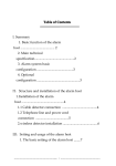
DS 85 BOOSTER POWER SUPPLY / DATA REPEATER
The DS 85 may be used to supply 48V DC power to an intercom line (string) and/or to enforce (repeat)
the data stream. The power and repeated data are supplied to its “Intercom Link Out” connector. The
unit has to be connected to a local mains outlet.
The DS 85 may be used :
In case of an intercom system with powered strings:
To boost the 48V power and to enforce the data stream in case of a long CAT-5 cable run (see max.
Cat-5 cable lengths).
In case of an intercom system with unpowered strings:
To enforce the data stream in case of a long Cat-5 cable run (see max.Cat-5 cable lengths). By
switching the mini switch on the rear of the unit Off, the DS 85 is not supplying 48V DC power and
becomes a data repeater only. When in such an intercom system wall boxes (DS 80) and/or non-selfpowered user stations (e.g. beltpacks) are used, the DS 85 supplies 48V DC power to those(sections
ASL DIGITAL USER MANUAL | 1 JANUARY 2011
11
of) strings to which these stations are connected (for this purpose the mini switch on the rear of the DS
85 has to be switched On)
WARNING: The DS 85 may only be put in the „through intercom line‟, so not between a DS 80 Wall
Box and the user station connected to it, nor between a DS 88 hub and the user stations connected to
one or more of its 8 outputs.
DS 85 Front Panel
1
MAINS power on/off switch
2
LED Indicator
Turns YELLOW when local mains power is fed to the unit and turns GREEN when the internal
PSU is switched on (see “Remotely switching on the DS 85”)
3
LED Indicator
Turns GREEN when 48V DC power is fed to the outgoing intercom line (“Intercom Link Out”)
and turns RED when there‟s an overload or short circuit on the outgoing intercom line.
DS 85 Rear Panel
4
MAINS entrance + fuse holder
5
INTERCOM IN connector (Neutrik Ethercon)
6
INTERCOM LINK OUT connector (Neutrik Ethercon)
with warning text: 'When green LED on the front panel is lit, this connector has +48V DC
power on pin 4 and 5‟
7
MINI Switch
When On, 48V DC power is fed to the outgoing intercom line (“Intercom Link Out”), provided
the internal PSU is switched on. When this mini switch is off, the DS 85 operates as a data
repeater only.
For Pin configurations, see Technical Specifications
Remotely switching on/off the power supply section of the DS 85 :
After a matrix unit is switched on, it sends a handshake signal its 5 intercom lines (strings). This signal
triggers an electronic switch in the DS 85 by which its power supply section is switched on. As soon as
a matrix unit is switched off, the handshake signal disappears from the string and, after 30 seconds,
the power supply section of the DS 85 switches off.
ASL DIGITAL USER MANUAL | 1 JANUARY 2011
12
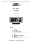
C3.
DS 88 HUB
The DS 88 Hub is used when a STAR wiring configuration is required. It has 1 incoming
intercom line (string) coming from a matrix unit and having 8 Intercom Out connectors to each
of which one user station can be connected. When there is 48V DC power on the incoming
intercom line, this power appears at the 8 Intercom Out connectors. The electronic circuitry of
the unit is fed by a built-in power supply, powered by a local mains outlet.
DS 88 Front Panel
1
Yellow LED
indicates whether local mains power is fed to the unit
2
Green LED
indicates whether the built-in power supply is enabled (see “remotely switching on the DS 88”)
DS 88 Rear Panel
3
INTERCOM IN connector
(1x Neutrik Ethercon) to connect the intercom line (string) coming from a matrix unit.
4
INTERCOM OUT connectors
(8x Neutrik Ethercon) with warning text: 'When green LED on the front panel is lit, these
connectors have +48V DC power on pin 4 and 5‟.
5
MAINS entrance + fuse holder
It is essential that the DS 88 is properly connected to ground of the local mains outlet.
For maximum Cat-5 cable lengths, see ASL Digital User Manual
For Pin configurations, see Technical Specifications
Remotely switching on/off the power supply section of the DS 88:
After a matrix unit is switched on, it sends a handshake signal to its 5 intercom lines (strings). This
signal triggers an electronic switch in the DS 88 by which its power supply section is switched on. As
soon as a matrix unit is switched off, the handshake signal disappears and, after 30 seconds, the
power supply section of the DS 88 switches off.
ASL DIGITAL USER MANUAL | 1 JANUARY 2011
13
C4.
DS 4000 MASTER MATRIX / DS 4000 SLAVE MATRIX
(Front Panel of a Master Matrix Unit)
(Front Panel of a Slave Matrix Unit)
C4.1
INTRODUCTION
These 19”/1RU matrix units each serve a maximum of 40 user stations and 2 interface modules. Six
matrix units can be linked to serve maximum 240 users and 12 interface modules. In case more
interfaces are required, the additional interfaces are mounted in a DS700 Interface box. Each
additional interface takes one user position.
Matrix units may be linked by either a CAT-5 wire, a COAX wire or a FIBER OPTIC wire . For each
type of wire there is a Matrix Link Module available, to be installed in the rear panel of each matrix unit.
On board the DS 4000 M are a DSP engine, a micro-processor and a linux computer:
o The DSP controls the data to the 5 intercom lines (strings) and takes care of the
communication with the matrix link module and the on-board interfaces.
o The tasks of the micro processor are : temperature measurement / fan speed regulation,
string current control, display management, GPIO control, PSU control
o The computer informs the DSP about the activated system configuration („event‟) and controls
the various USB connections.
BLOCK DIAGRAM OF THE DS 4000 MASTER MATRIX UNIT
ASL DIGITAL USER MANUAL | 1 JANUARY 2011
14
A matrix unit (master or slave) supplies 48V DC power to its 5 intercom lines (strings). The start-up is
as follows:
o The unit powers up with all strings switched off
o The internal micro-processor first determines the status of both power supplies and checks the
temperatures of power supplies and electronics
o The processor switches on the power to the first string and measures the current. If the
current is to high, the power will be switched off
o The processor powers up the next string etc.
After the power to all strings has been switched on, the processor continuously monitors all string
currents, every few milliseconds. The status of each string (On and Overload) is shown by green and
red LED‟s on the front panel.
A matrix unit (master or slave) has two internal power supplies. Three fans with auto variable speed
provide forced cooling.
The maximum current to a string to 2A, but the maximum current to all strings together is set to 5A.
Peak currents can be a little higher for a limited amount of time. When the load on the strings is such
that the maximum total current of 5A is in danger to be exceeded, the power to all strings automatically
shuts off.
In installations where powered strings are not allowed, the 48V DC string power can be switched off by
an internal jumper in each matrix unit.
A master matrix unit (DS 4000M) has USB, VGA and Ethernet connectors USB, which are not to be
found on a slave matrix unit (DS 4000S).
The RJ45 Ethernet connectors on the front and the rear of the unit are for a normal 10/100 T base
network connection. The rear RJ45 connector usually connects to a normal network switch or hub, the
front RJ45 connector usually connects directly to a computer. The built-in Ethernet switch
automatically adapts to the speed of the connected network and has „Auto Negotiation‟ according to
the IEEE 802.3x standard, so that to both RJ45 connectors straight or crossed cable may used.
The RJ45 connectors have Led‟s to indicate status and activity of the network connection.
All USB connectors are fully compatible with the USB 1.1 and 2.0 standard and directly connect to the
computer in the master matrix. Each USB connector may be used to connect:
- USB storage devices such as flash disks, hard disks etc.
- USB keyboards
- USB pointer devices such as Mouse, Trackball etc.
- USB touch screen
The VGA is a normal computer VGA output. It supplies analog RGB video information, sync and 12C
communication to the monitor.
IMPORTANT NOTICE : Due to the depth and the weight of the DS 4000, it needs to have rear support
when mounted in a 19” rack.
C4.2
CONTROLS & CONNECTORS
DS 4000 M (master)FRONT PANEL CONTROLS & CONNECTORS
ASL DIGITAL USER MANUAL | 1 JANUARY 2011
15
1
POWER ON/OFF switch + LED
A Mains On/Off push button and „On‟ LED
2
„On‟ LED‟s
LED‟s (one for each string) which indicate string power
3
„Overload‟ LED‟s
LED‟s (one for each string) which indicate overload
4
Oled Display
This display shows:
The sequential number of the DS 4000: Matrix #1 (= System Master) or Matrix #2 or Matrix #3
etc.
The status of the internal power supplies (PSU 1: OK, PSU 2: OK)
The status of the internal DSP (DSP: OK)
Current to each intercom line
Temperatures (PSU1, PSU2, CPU, PCB)
The on board Interface Modules (type and ID of each)
Shutdown procedure
o
o
o
o
o
o
o
5
USB connector
Through this USB connector, the matrix settings can be stored on a USB stick or any other
store device. The connector may also be used to connect a mouse or a keyboard.
6
ETHERNET connector
An RJ45 connector usually to connect to a (laptop) PC or Apple computer or else to a
computer network (LAN). See also chapter D “Configuration Software”
DS 4000 M (master) REAR PANEL CONNECTORS
7
VGA Connector
To connect a monitor or the video section of a touch-screen to the matrix unit. The VGA
connector supplies analog RGB video information, sync and I2C communication to the monitor
8
ETHERNET connector
One RJ45 connector usually to connect to a computer network (LAN) or else directly to a PC
or Apple (laptop) computer (see also chapter D “Configuration software” )
9
USB connectors
Two USB connectors, of which one is needed in case a touch screen is used (leads the „touch
information‟ to the matrix master unit)
10
Slots for Interface Modules
Two slots for Interface modules, marked A and B
11
Slot for Matrix Link Modules
For either a Coax Matrix Link module (DS 52) or a Fibre Optic Matrix Link module (DS 53) or a
CAT5 Matrix Link module (DS 54)
12
INTERCOM OUT connectors
Five Ethercon connectors to connect the intercom lines (strings) to.
ASL DIGITAL USER MANUAL | 1 JANUARY 2011
16
13
Sub-D connectors
Two Sub-D Connectors for General Purpose I/O, each 4x IN and 4x OUT)
14
MAINS connector + FUSE holder
To connect a power cord which is connected to a mains outlet (90 - 240 V AC, 50/60 Hz). The
FUSE holder houses two fuses, each T6.3A (slow blow)
DS 4000 S (slave) FRONT PANEL CONTROLS & CONNECTORS
POWER ON/OFF switch + LED
A Mains On/Off push button and „On‟ LED
„On‟ LED‟s
LED‟s (one for each string) which indicate string power
„Overload‟ LED‟s
LED‟s (one for each string) which indicate overload
Oled Display
Showing various (failure) reports. See DS 4000 M.
DS 4000 S (slave) REAR PANEL CONNECTORS
Slots for Interface Modules
Two slots for Interface modules, marked A and B
Slot for Matrix Link Modules
For either a Coax Matrix Link module (DS 52) or a Fibre Optic Matrix Link module (DS 53) or a
CAT5 Matrix Link module (DS 54)
INTERCOM OUT connectors
Five Ethercon connectors to connect the intercom lines (strings) to.
Sub-D connectors
Two Sub-D Connectors for General Purpose I/O, each 4x IN and 4x OUT)
MAINS connector + FUSE holder
To connect a power cord which is connected to a mains outlet (90 - 240 V AC, 50/60 Hz).
The FUSE holder houses two fuses, each T6.3A (slow blow)
C5.
C6.
C7.
MATRIX LINK MODULES
FUNCTION BUTTON PANELS
2-CH SPEAKER STATION
T.B.A.
T.B.A.
T.B.A.
ASL DIGITAL USER MANUAL | 1 JANUARY 2011
17
C9.
DS 830 TABLETOP 8-CH SPEAKER STATION
C10.
DS 1630 TABLETOP 16-CH SPEAKER STATION
C11.
DS 2430 TABLETOP 24-CH SPEAKER STATION
C12.
DS 3230 TABLETOP 32-CH SPEAKER STATION
All tabletop speaker stations have the same functions as the DS 1640 Speaker Station (see
Chapter C13), but have only one GPI/O connector and only one PGM Audio input connector. The
units may be mounted in a 19”rack using a 3RU rack mounting kit.
ASL DIGITAL USER MANUAL | 1 JANUARY 2011
18
C13.
DS 1640 DIGITAL SPEAKER STATION / DS 2040 EXTENSION PANEL
C13.1 INTRODUCTION
DS 1640 Speaker Station:
The DS 1640 speaker station (19”/1RU) has 16 channels with Talk and Listen functions at each
channel. It has a master section consisting of a master display, programmable function buttons, a
keypad, a Mic On button, a Solo button and a PTP button.
Each channel is assigned to a user group as defined by the system administrator in the configuration
software. Besides communication via the user groups, the user can initiate PTP (Person to Person)
communication (like a private telephone call) and send/receive Text Messages (SMS).
Each user ID number refers to a user name, which may be the name of a person (e.g. John Smith) or
a job title (e.g. Stage Manager). It is also possible to refer to a location, e.g. Dressing Room. The ID
number is then rather a 'station number', but in the configuration software still called 'user number'.
For each configuration (event) a list of user ID numbers and belonging user names is made.
The channel displays show the group names and a Listen Volume bar, the master display shows the
assignments of the function buttons, the menu items and the text messages.
The alpha-numerical keypad allows the user to enter ID numbers and user names. The Menu button
on the Keypad is used to enter the Menu and to exit the Menu.
Connecting the DS 1640 speaker station to an intercom line ('string'), one uses the 'Intercom In'
connector. The 'Intercom Link Out' connector is used in case of a daisy chain wiring configuration.
When the DS 1640 is in a daisy chain, it has to be switched On. If not, the data are not sent to the next
user station.
The ASL electret gooseneck microphone is of the noise cancelling type. Also available is an ASL
gooseneck mic with LED ring, indicating when the mic is active.
A headset may be connected via the XLR-4 connector on the DS 1640 front panel. For the headsetand gooseneck microphone limiters preserve the mic signal path from clipping. A presence filter
(proprietary frequency correction) provides high intelligibility.
The DS 1640 has a built-in power supply, supplying power to its electronics.
DS 2040 Extension Panel (NOT AVAILABLE YET):
The DS 2040EP (19”/1RU) has 20 channels, no master section. It may be linked to the DS 1640, thus
forming a 36-channel speaker station. The DS 2040EP has a built-in power supply, supplying power to
its electronics, and a uP which communicates serially with the DS 1640.
ASL DIGITAL USER MANUAL | 1 JANUARY 2011
19
C13.2 CONTROLS & CONNECTORS
DS 1640 & DS 2040EP FRONT PANEL CONTROLS & CONNECTOR
1
Channel Displays (DS 1640 & DS 2040EP)
These OLED displays show the name of the groups assigned to each channel, using 2 rows of
4 characters. A third row (in the top of the display) shows a volume bar indicating the listen
level of each channel.
2
Master Display (DS 1640 only)
This OLED display shows the assigned function buttons, the menu functions (after entering
the menu), the PTP functions (during PTP mode) and user ID number (during login
procedure).
NOTE: In fixed installations, the intercom system often remains to be switched on
permanently. In order to lengthen the lifetime of the Oled displays it‟s highly
recommended to put the DS 1640 and DS 2040EP into “Standby Mode”, when not in
use (see chapter B5.3)
3
TALK Buttons (one for each channel), either latching or momentary:
Latching: When a TALK button is pushed shortly, the microphone signal is sent to the
chosen channel and the TALK button is latching. When pushed again and the Talk
function switches off. For each channel separately, the latching function can be
disabled by the system administrator in the ConfigurIT software. The TALK button is
then momentary only.
Momentary: When holding a TALK button pushed for at least 2 seconds, the
microphone signal is sent to the chosen channel until the button is released. When
released the Talk function switches off automatically.
A TALK button contains a full colour (RGB) Led. When the TALK button is switched on, it is
lit GREEN, provided the MIC On button was activated. If the TALK button is switched on, but
not the MIC ON button, the TALK button is lit YELLOW.
The system administrator may - in the ConfigurIT software, for each user station - disable the
Talk function (per channel).
A switched on TALK button can be remotely switched off by a REMOTE TALK MUTE signal
sent from a function button on a multichannel speaker station or on a separate function
button panel. After a TALK MUTE signal has been received, the user may switch on the
TALK button(s) on his speaker station by pushing these button(s).
The system administrator may in the ConfigurIT software disable the REMOTE TALK MUTE
SEND and/or the REMOTE TALK MUTE RECEIVE functions
4
LISTEN Buttons (one for each channel)
These buttons are lit by full colour (RGB) Led‟s and enable the listen function of each channel.
If switched on, the buttons are lit green. The listen level of each channel is shown in the
channel displays by a volume bar and are adjusted by pushing and holding the equivalent
ASL DIGITAL USER MANUAL | 1 JANUARY 2011
20
listen button and turning the Volume encoder. For listen volume settings in SOLO mode, see
'SOLO button'.
5
GOOSENECK Jack Connector (DS 1640 only)
This connector holds the gooseneck microphone which may be of the electret or dynamic
type. The mic signal path for either mic type has to be adjusted by the user, via menu item #9
'GOOSENECK MIC TYPE' or by the system administrator in the ConfigurIT software.
NOTE: The pin configuration of the gooseneck jack connector and the ASL gooseneck
microphone differ from what is usually found in the professional audio industry ! So a
gooseneck mic of another make can‟t be used, unless the pin configuration of that third party
microphone has been (internally) changed. For details, see Technical Specifications
6
HEADSET Connector (DS 1640 only)
Via this XLR-4 connector the headset may be connected. At a binaural speaker station, the
XLR-4 connector is replaced by an XLR-5 headset connector.
The speaker station accepts headsets with microphones of the dynamic or electret type. The
mic signal path for either type has to be adjusted by the user, via menu item #7 'HEADSET
MIC TYPE' or by the system administrator in the ConfigurIT software.
As soon as a headset is plugged in the speaker and gooseneck microphone are automatically
disabled. The speaker can be switched on again by using the Function Button SPKR ON/OFF
(both the headset and the speaker are now on).
Side Tone:
Using a headset, ones own voice is heard in the headset cans. This is called 'Side Tone',
which may be adjusted by the user via menu item #6 „SIDE TONE HEADSET‟ or by the
system administrator in the ConfigurIT software.
The side tone at multichannel speaker stations is related to the level of the master volume
control. When changing the master volume, the side tone level changes accordingly.
Output amplifiers for headset:
The output amplifiers have a current limiter. The (bridged) amplifiers are optimized for 200
ohm (2 headset cans parallel, each 400 ohm). Lower and higher impedances are supported
but performance may decrease.
o
o
o
For both gooseneck and headset mic:
For each type of gooseneck or headset microphone there is a default gain setting: 0
dB for electret mics and +30 dB for dynamic mics. These default settings may be
adjusted with -4 dB to +20 dB, by the user via menu item #8 „HEADSET MIC GAIN‟
and menu item #10 „GOOSENECK MIC GAIN‟ or by the system administrator in the
ConfigurIT software
A built-in limiter prevents the mic signal path from clipping
A presence filter (proprietary frequency correction) provides high intelligibility. This
filter may be switched on or switched off, by the user via menu item #12 'PRESENCE
FILTER' or by the system administrator in the ConfigurIT software
ASL DIGITAL USER MANUAL | 1 JANUARY 2011
21
7
LOUDSPEAKER (DS 1640 only)
Through this 1,5” x 2,5 “ loudspeaker the intercom and PTP communication is heard as well
as the PGM signals and the Error, Ring, Engaged and Buzzer tones.
Output amplifier:
The output amplifier has a current limiter, set to max 1,25A.
Speaker Attenuator :
When the gooseneck microphone is switched on, the output of the loudspeaker is attenuated.
This to avoid that the signal from the speaker enters the microphone (feedback). The degree
of attenuation may be adjusted by the user via menu item #25 „SPEAKER ATTENUATOR‟ or
by the system administrator in the ConfigurIT software
8
SOLO Button (DS 1640 only)
This button activates the SOLO mode of the station. When pushed the SOLO button is lit
WHITE. When a TALK button of the required channel is pushed whilst the unit is in SOLO
mode, this TALK button is momentary only and the equivalent LISTEN button will switch on
automatically. All TALK and LISTEN functions of the remaining channels will switch off. The
SOLO button now flashes WHITE. The MIC ON button switches on automatically, if it was
switched off before. For as long as the TALK button is pushed, the user talks and listens to the
chosen channel (i.e. its assigned group). The level of the “Solo conversation” can be adjusted
by turning the volume knob (rotary encoder).
Upon release of the TALK button the previous Talk and Listen volume settings will be
restored. If the SOLO button is switched on and no TALK button is pushed, the unit is still
functioning as usual.
When the station is in SOLO mode and one pushes a LISTEN button (momentary only), one
listens to the selected channel only. One can adjust the listen level of that channel by turning
the volume knob (rotary encoder). The LISTEN buttons of the remaining channels switch off,
as well as the MIC ON button and all TALK buttons. Upon release of the LISTEN button the
previous Listen volume settings will be restored.
9
MIC ON Button (DS 1640 only)
This button is latching or momentary.
When switched on, the MIC ON button is lit YELLOW when none of the TALK buttons are
activated. When the MIC ON button is switched on and one or several TALK buttons are
activated, the MIC ON button is lit GREEN and the microphone signal is sent to the selected
channels. If TALK buttons are activated but the MIC ON is switched off, those TALK buttons
are lit YELLOW, meaning no signal is sent to the selected groups.
When SOLO mode or PTP mode or the function MIC DIRECT OUT (see chapter 13.7) is
activated, the MIC ON button switches on automatically.
10
VOLUME Knob / Encoder (DS 1640 only)
This rotary encoder controls the volume of the intercom and PGM audio input signals as heard
in the speaker or headset by turning it.
By pushing and turning the rotary encoder, the volume of the PGM signals (locally fed into
one or both PGM inputs) may be adjusted in the required balance with the intercom signals.
So the rotary encoder is the MASTER volume control for intercom and PGM signals, but may
be programmed in a setting by which the Intercom volume and the PGM volume are adjusted
independently (see menu item #24 „Master Volume‟)
The balance of the listen level between speaker and headset is determined in the firmware.
The rotary encoder is also used to adjust the listen level of each channel (indicated by a
volume bar in the channel display) by pushing and holding the LISTEN button of the required
channel and turning the VOLUME control.
Whilst adjusting the listen level of one of the channels, one listens to all other channels of
which the LISTEN button is switched on.
ASL DIGITAL USER MANUAL | 1 JANUARY 2011
22
In case one wants to adjust the listen level by listening to that channel only, one first pushes
the SOLO button followed by the LISTEN button of that channel and then adjusts the listen
level by turning the VOLUME control.
The rotary encoder is also used to scroll through the Menu and PTP items. During PTP
communication, the PTP listen level can be adjusted by turning the volume control (it will only
effect the volume of the PTP communication – no other settings will change).
11
PTP Button (DS 1640 only)
The PTP button initiates an outgoing PTP (Person to Person) call or takes an incoming PTP
call (see description of PTP communication) and is also used in Text Messaging procedures.
12
FUNCTION Buttons F1, F2, F3, F4 (DS 1640 only)
The user may assign a number of functions to the 4 function buttons (F1 - F4) on his speaker
station. By pushing the SHIFT button in the keypad, four other functions may be assigned to
these function buttons. (see chapter C13.6 “Assigning functions to function buttons”).
Assigned functions are shown in the master display, below each of the function buttons.
To activate a function, the equivalent function button is pushed.
13
KEYPAD (DS 1640 only)
This Alpha-Numerical keypad is used to enter ID numbers and names and includes a MENU
button and a SHIFT button. The MENU button is used to enter or exit the Menu, to confirm the
ID number when logging in and to log out the speaker station.
DS 1640 REAR PANEL CONTROLS & CONNECTORS
14
MAINS Connector + fuse holder
This entrance with fuse holder allows mains power to be connected.
15
MAINS Switch
Mains is switched on/off by the switch next to the mains entrance.
16
INTERCOM IN Connector (Ethercon)
For connecting the CAT-5 cable (String) coming from a matrix unit or - when having a „daisy
chain‟ wiring - coming from another user station or - when having a „star‟ wiring - coming from
a hub or – when having a „Line‟ wiring – coming from a wall box.
17
INTERCOM LINK OUT Connector (Ethercon)
When having a daisy chain wiring configuration, to connect the CAT-5 cable to the next user
station.
18
EXTERNAL SPKR Connector
This 6,3mm jack allows the connection of an external speaker. The internal speaker is
automatically switched off. The use of a normal mono jack is sufficient.
To use the internal and external speaker simultaneously, a stereo jack is needed (with an
internal link). See user manual for wiring instructions.
19
PGM Inputs
This two XLR-3F connectors accept PGM signals (locally fed program signals) on balanced
line level which are routed to ones own speaker and/or headset only. In case the station is
binaural, a stereo PGM signal may be sent to the headset (see chapter C 13.9).
ASL DIGITAL USER MANUAL | 1 JANUARY 2011
23
20
MIC DIRECT OUT Connector
This XLR-3M connector outputs the microphone signal on balanced line level and is often
used for „Stage Announce‟. It is activated by pushing and holding the function button to which
the „Mic Direct Out‟ function has been assigned.
21
EXTENSION PANEL Connector
Via this D-connector the DS 1640 and the DS 2040EP are linked.
22
GPI/O Connectors 1 and 2
These D-connectors each hold 4 general purpose inputs and 4 outputs. To these Dconnectors also an IS 141 Beacon may be connected.
DS 2040EP REAR PANEL CONTROLS & CONNECTORS
(DS 2040EP Rear Panel)
MAINS Connector and Switch
This entrance with fuse holder allows mains power to be connected. Mains is switched on/off
by the switch next to the entrance.
EXTENSION PANEL Connector
Via this D-connector the DS 1640 and the DS 2040EP are linked.
DS 50 Connector
Via this D-connector, a DS 50 Function Button panel can be linked.
C13.3
CONNECTING THE IS141 BEACON
To the D-connectors on the DS 1640 speaker station the IS 141 Analog Beacon may be connected,
with a cable having at one end an XLR-3 connector (to the beacon) and at the other end a Dconnector cable part (to the Speaker Station). Through this cable 28V DC power is fed from the
Speaker Station to the Beacon. When one or more channels at the Speaker Station a (digital) Call
signal is activated, an 6V DC signal is sent to the beacon to activate the beacon light and buzzer.
C13.4
REMOTELY SWITCHING THE DS 1640 ON/OFF
C13.5
DASHBOARD LIGHTING & LED BRIGHTNESS
T.B.A.
Dashboard Lighting:
When a push button is „off‟‟, it is lit WHITE at a low intensity. This is called Dashboard Lighting,
allowing the user to always easily see and find all push buttons. The user may adjust the intensity of
this dashboard lighting on his own station, by entering menu item #4 „DASHBOARD LIGHT‟. Whilst
adjusting the dashboard light intensity value, the intensity of all buttons changes to show the user how
each of these steps look like. The dashboard light intensity may also be set by the system
administrator in the ConfigurIT software, separately for each connected station.
LED Brightness:
When a push button is pushed to be switched „On‟, its LED turns WHITE, GREEN, YELLOW, RED or
BLUE, depending on its function or status. The user may adjust the LED brightness for his own
station, by entering menu item #5 „LED BRIGHTNESS‟ . While adjusting the light intensity value, the
intensity of all buttons changes to show the user how each of these steps look like. The LED
ASL DIGITAL USER MANUAL | 1 JANUARY 2011
24
brightness may also be set by the system administrator in the ConfigurIT software, separately for each
connected station.
C13.6
ASSIGNING FUNCTIONS TO FUNCTION BUTTONS
Functions are assigned by the user, by entering menu item #26 „FUNCTION BUTTON ASSIGN‟.
A list of all for the user available functions is shown of which a maximum of 8 functions can be
assigned. The list of functions also shows, at each function, whether that function already has been
assigned and if so, to which function button. That function button may be emptied by pushing key 0 of
the keypad.
With the Rotary Encoder one scrolls through the list and selects a function. The selected function is
assigned to the function button which is now pushed (F1 or F2 or F3 or F4 in WHITE / Shift F1, or Shift
F2 or Shift F3 or Shift F4 in RED).
In case a function button (for instance Shift F2) already holds a function, the display shows:
' Shift F2 IN USE '
' KEY 1 = ASSIGN NEW'
' KEY 2 = KEEP OLD '
If one chooses 'Assign New", the previously assigned function is no longer assigned to any of
the function buttons.
If one chooses 'Keep Old', the selected function may be assigned to one of the other function
buttons, either empty ones or assigned ones.
For a description of the available functions, see chapter C13.7.
NOTE: By pushing a function button, the assigned function is activated or de-activated, provided the
display shows the function names. When the display shows something else (for instance during Login,
Menu mode, PTP mode, volume change, change group positions), the function buttons are
temporarily disabled.
C13.7
FUNCTIONS TO BE ASSIGNED TO THE DS 1640 FUNCTION BUTTONS
The functions which may be assigned to the Function Buttons are listed underneath
13.7.a
„Call To‟
CALL
TO
After the CALL TO function button is pushed it flashes slowly WHITE . Then one
pushes the TALK button of the channel with the group one wants to send a call to.
The pushed TALK button as well as the related LISTEN button start flashing RED.
The Call signal is sent for as long as the TALK button is held and after 2 seconds the
Call Buzzers are activated, both in ones own station and in the called user stations
(the ones which are in the group which is assigned to the chosen channel).
One may also send a Call to several groups simultaneously. Then the TALK buttons
(including the ones which are programmed NOT LATCHING) of the equivalent
channels are pushed, only the last one has to be held and pushed for 2 seconds to
activate the Call buzzers.
After releasing the TALK button(s), the Call buzzers switch off and the TALK and
LISTEN buttons continue flashing for another 3 seconds. After this, the CALL TO
function button switches off.
ASL DIGITAL USER MANUAL | 1 JANUARY 2011
25
When the CALL TO function button has been pushed but no TALK button has been
pushed within 5 seconds, the CALL TO function button switches off and no call is sent.
By sending a call to one or more channels, the LISTEN buttons and the TALK buttons
(except the ones which are programmed NOT LATCHING) of those channels
automatically switch on. The MIC ON button is NOT automatically switched on.
NOTE: The system administrator may have disabled this function (see menu item #20
“CALL SEND ENABLE” When the function button is pushed to which this function has
been assigned, the display shows (alternating) the function name and the message:
„Function Disabled‟. (FNCT DIS ABLD)
13.7.b
„Call To Talk‟
CALL
TO
TALK
After the CALL TO TALK function button is pushed, it is shortly lit WHITE and a Call
signal is sent automatically to all channels (and to their assigned groups) with a
switched on TALK button, irrespective the MIC On button being switched on or off.
These TALK buttons and related LISTEN buttons are now flashing.
- the TALK button flashes alternately RED and in the colour of its previous
Talk status (yellow or green).
- the LISTEN button flashes alternately RED and in the colour of its previous
Listen status (yellow or green, see note below).
The function button is held and pushed for as long as the call signal is supposed to be
sent. After 2 seconds the call buzzers will be activated. After releasing the CALL TO
TALK function button, the call buzzers switch off and the TALK and LISTEN buttons
flash for another 3 seconds. After this, the function button switches off.
By sending a call to one or more channels, the LISTEN buttons of those channels
automatically switch on. The MIC ON button is not automatically switched on.
It is evidently not possible to send Call to channels of which the TALK buttons are
programmed “NOT LATCHING” .
NOTE: The system administrator may have disabled this function (see menu item #20
“CALL SEND ENABLE” When the function button is pushed to which this function has
been assigned, the display shows (alternating) the function name and the message:
„Function Disabled‟. (FNCT DIS ABLD)
Notes for „Call To‟ and „Call to Talk‟ functions:
A Function button with a „Call-To„ or a „Call-To-Talk‟ function is LATCHING,
but switches off automatically as soon as the Call procedure is accomplished.
The level of the Call Buzzer is adjustable at each user station, by the user via
menu item #21 'BUZZER VOLUME' or by the system administrator in the
ConfigurIT software.
The user may switch the buzzer on his own station On or Off, by pushing the
function button to which the function “BUZZER ON/OFF” has been assigned.
After a 'Remote Buzzer Mute' signal has been received from a function button
at another multichannel speaker station or on a function button panel, the
ASL DIGITAL USER MANUAL | 1 JANUARY 2011
26
buzzer cannot be switched on until the 'Remote Buzzer Mute' status is
abolished (see chapter 13.7.h).
13.7.c
„Talk To All‟
TALK
TO
ALL
After the TALK TO ALL function button is pushed and held (momentary only):
All TALK buttons on ones station (except the ones which are DISABLED) and the MIC
ON button switch on. One may now talk to all groups which are assigned to the ones
user station. Upon release of the function button it switches off and all settings go to
back to their previous status.
13.7.d
„Speaker On/Off‟
SPKR
ON /
OFF
By pushing the SPKR ON/OFF function button the speaker at ones own station (or its
external speaker) switches On or Off. The function button is lit WHITE when the
speaker is ON and Off when the speaker is Off.
As soon as a headset is connected, the speaker switches Off automatically and the
function button light extinguishes. In case one wants to have both the headset and the
speaker active, one now pushes the SPKR ON/OFF function button by which the
speaker switches on again.
As soon as the headset is disconnected:
If the speaker was switched Off before, it switches On automatically
If the speaker was switched On before, it will stay On.
NOTE: The gooseneck microphone is Off when a headset connected and is On when
there‟s no headset connected.
13.7.e
„Remote Talk Mute Send'
REM.
TALK
MUTE
This function is also known as MIC KILL.
After the REMOTE TALK MUTE function button is pushed, it is shortly lit RED and a
Talk Mute signal is sent to all groups assigned to ones user station.
On all user stations (including the station of the initiator) the TALK buttons of the
channels which are assigned to these groups switch Off (if they were On before)
On each user station, these TALK buttons may be switched on again by pushing
them.
Channels which should not be sensitive for a Remote Talk Mute signal, (those
channels should not switch off), need to have a disabled REMOTE TALK MUTE
MUTE RECEIVE, see menu item #18.
The system administrator may have, for each user separately, disabled the REMOTE
TALK MUTE SEND function (see menu item #17, REMOTE TALK MUTE SEND”).
ASL DIGITAL USER MANUAL | 1 JANUARY 2011
27
When the function button is pushed to which this function has been assigned, the
display shows (alternating) the function name and the message: „Function Disabled‟.
(FNCT DIS ABLD)
13.7.f
„Remote Talk Mute Send Per Group‟
TALK
MUTE
GRP
By pushing the REMOTE TALK MUTE PER GROUP function button it is lit RED.
Now one pushes the TALK buttons of those channels with the groups one wants to
send a “Remote Talk Mute” signal to.
On all user stations (including the station of the initiator) the TALK buttons of the
channels which are assigned to these groups switch Off (if they were On before)
On each user station, these TALK buttons may be switched on again by pushing
them.
After the “Remote Talk Mute” signal is sent, the REMOTE TALK MUTE function button
switches off.
Channels which should not be sensitive for a Remote Talk Mute signal, (those
channels should not switch off), need to have a disabled REMOTE TALK MUTE
MUTE RECEIVE, see menu item #18.
The system administrator may have, for each user separately, disabled the REMOTE
TALK MUTE SEND function (see menu item #17 “REMOTE TALK MUTE SEND”).
When the function button is pushed to which this function has been assigned, the
display shows (alternating) the function name and the message: „Function Disabled‟.
(FNCT DIS ABLD)
13.7.g
„Remote Speaker Mute Send‟
REM.
SPKR
MUTE
After the REMOTE SPEAKER MUTE function button is pushed, it is shortly lit RED
and a Remote Speaker Mute signal is sent to all groups assigned to ones user station.
On all user stations with channels assigned to these groups and on the user station of
the initiator, the speaker and the SPKR ON/OFF function button switch Off (if they
were On before). The speaker on each user station may be switched on again by
pushing the SPKR ON/OFF function button.
The above requires that the SPKR ON/OFF function is assigned to one of the function
buttons on all of these stations.
User stations which should not be sensitive for a Remote Speaker Mute signal (their
speakers should not switch off), need to have a by tHe system administrator disabled
REMOTE SPEAKER MUTE RECEIVE, see menu item #14.
The system administrator may have, for each user separately, disabled the REMOTE
SPEAKER MUTE SEND function (see menu item #13, REMOTE SPEAKER MUTE
SEND”). When the function button is pushed to which this function has been assigned,
the display shows alternating the function name and the message: „Function Disabled‟.
(FNCT DIS ABLD)
ASL DIGITAL USER MANUAL | 1 JANUARY 2011
28
When the intercom system is switched off (deliberately or as a result of unexpected
power loss) and switched on again, the speakers are Off when a headset is connected
and On when there‟s no headset connected.
13.7.h
„Remote Buzzer Mute Send‟
REM.
BUZZ
MUTE
By pushing the REMOTE BUZZER MUTE function button it is lit RED and a Remote
Buzzer Mute signal is sent to all groups at ones station.
On all user stations with channels assigned to these groups and on the user station of
the initiator the buzzer switches off. The BUZZER ON/OFF function button is now lit
RED as an indication that the station has now a “Buzzer Mute Status”.
The user of a station in Buzzer Mute Status cannot switch on his own buzzer again.
This has to be done by the initiator, by pushing his REMOTE BUZZER MUTE function
button again, which turns from RED to Off. The Buzzer Mute Status is now abolished
and on all stations the BUZZER ON/OFF function button turns from RED to its
previous setting.
The above requires that the BUZZER ON/OFF function is assigned to one of the
function buttons on all of these stations.
User stations which should not be sensitive for a Remote Buzzer Mute signal (the
buzzer should not switch off), need to have a disabled BUZZER MUTE RECEIVE, see
menu item #23.
The system administrator may have, for each user separately, disabled the REMOTE
BUZZER MUTE SEND function (see menu item #22). When the function button is
pushed to which this function has been assigned, the display shows alternating the
function name and the message: „Function Disabled‟. (FNCT DIS ABLD)
A Remote Buzzer Mute signal does not affect the buzzer on the station of the initiator
When the intercom system is switched off whilst a Buzzer Mute Status is activated,
this status is still active after the system is switched on again.
13.7.i
„ Buzzer ON/OFF‟
BUZZ
ON /
OFF
By pushing the BUZZER ON/OFF function button (latching) the buzzer at ones own
station switches On or Off. The function button is lit WHITE when the buzzer is ON
and Off when the buzzer is Off.
The BUZZER ON/OFF function button is lit RED after a Remote Buzzer Mute signal
has been received, indicating that the station has a Buzzer Mute Status (see 13.7. h)
13.7.k
„Stop PTP Receive'
STOP
PTP
REC.
ASL DIGITAL USER MANUAL | 1 JANUARY 2011
29
By pushing the STOP PTP RECEIVE function button it is lit RED and the station can
not be reached through a PTP call. During 5 seconds the sender of a PTP call gets an
Engaged tone in his headset or speaker and the message ENGAGED in his display.
To enable to receive PTP calls again, the STOP PTP RECEIVE function button is
pushed again and switches off.
13.7.l
„Mic Direct Out'
MIC
DRCT
OUT
This function is also known as „Stage Announce‟
By pushing and holding (momentary only) the MIC DIRECT OUT function button, it is
lit WHITE. If the MIC ON button was off, that button switches on. The microphone
signal is now sent to the MIC DIRECT OUT connector on the rear panle of the
speaker station and via this connector to third party PA systems. All intercom LISTEN
and TALK buttons switch off. After release of the function button the TALK and
LISTEN buttons are enabled again (go back to their previous setting).
When a gooseneck microphone with LED ring is installed, this ring switches on when
the MIC DIRECT OUT function button is pushed.
C13.8
CHANGE GROUP POSITIONS AT ONES SPEAKER STATION
The system administrator determines – in the ConfigurIT software for each user station - which group
goes to which channel. In case the user wants to change these positions on his own station, the
following procedure allows him to do so:
1. Go into menu mode by pressing the menu button in the keypad section
2. Go to menu item #27 „Change Group Position' by turning and then pushing the rotary encoder.
The volume bars in the channel displays are no overwritten by the channel numbers (Ch01,
Ch02, Ch03 etc.)
3. The group of which its position has to move is marked by pushing the TALK button under that
group. The pushed TALK button is now lit YELLOW.
4. By turning the rotary encoder one drags the marked group to the newly required position. The
TALK buttons between 'start and finish' indicate the direction of the moving group, by shortly
switching on and off. The channel numbers stay where they are.
The not marked groups make way by shifting to the left when the marked group is dragged to
the right or by shifting to the right when the marked group is dragged to the left. In other
words: the marked group is „moved and inserted‟
5. One may also mark a block of groups which are next to each other by pushing the first and the
last TALK button of that block. In that case the whole block is dragged to its new position.
6. By pushing the rotary encoder, the new position is fixed and one may now move another
group or block of groups. By pushing the rotary encoder, the new position of these other
group(s) is fixed
7. One leaves this menu item by pushing the MENU button. The new group positions are sent to
the matrix and ConfigurIT and are stored. The channel numbers are now replaced by volume
bars.
ASL DIGITAL USER MANUAL | 1 JANUARY 2011
30
NOTE 1: During this procedure the master display shows 'Change Group Position' and all intercom
and PTP/SMS functions are disabled.
NOTE 2: The above also works for channel 17 - 36 of the DS 2040 Extension Panel
NOTE 3: Also the system administrator may change group positions, in the configuration software.
NOTE 4 : When groups are moved to other channels, the channel properties move as well. !!
C13.9
BINAURAL SPEAKER STATION
T.B.A.
C13.11
CONNECTING THE DS 1640 TO THE DIGITAL NETWORK
When connecting the speaker station to a string, it first checks whether a matrix is detected (the
master display shows: DETECTING MATRIX). In case this message stays in the display rather long,
there might be a broken cable or a faulty connector, hub or wall box.
Then the status of the chosen string is checked. If already 8 user stations are connected to that string,
all time slots are taken and the master display shows :
NO SERVICE
The user would then have to try another string to connect to.
The master display shows the user-ID number (3 digits, the first digit blinking) as last stored in the unit.
USER ID
123
If this is the ID number of the present user, one pushes the MENU button in the keypad
section by which the shown ID number is sent to the matrix. Provided this ID number is
registered in the active ('running') event, the speaker station now logs into the intercom
network and receives all settings belonging to this ID number as stored in the matrix.
Before the master display shows the function button assignments, it shortly (for 5 seconds)
shows the short name of the user linked to the ID number
USER ID
123
LUCY BALL
In case this is not the short name of the present user, he has to push the Menu button and has
to start the login procedure again. When the Menu button is pushed quickly (during the login
procedure), this procedure is interrupted. One may now enter another ID number (see
“adjusting the ID number”)
Adjusting the ID number:
One adjusts the ID number by overwriting the three digits using the keypad. Now the MENU
button is pushed by which the new ID number is sent to the matrix. Provided this ID number is
registered in the active ('running') event, the speaker station logs into the intercom network
and receives all settings belonging to that ID number as stored in the matrix (see also:
configuration software). The new ID number is stored in the speaker station.
ASL DIGITAL USER MANUAL | 1 JANUARY 2011
31
When an ID number is sent (from the speaker station to the matrix) to which in the ConfigurIT software
a type of user station is assigned which is different from the station type it is sent from, the following
applies:
When the in the ConfigurIT software assigned multichannel speaker station has more
channels (e.g.12) than those of the connected speaker station (e.g. 8), this speaker station
logs in but it receives only the channel information of the first 8 channels.
When the in the ConfigurIT software assigned multichannel speaker station has less channels
(e.g.8) than those of the connected speaker station (e.g. 12), this speaker station logs in but it
receives the channel information of 8 channels. The remaining 4 channels are disabled.
When the in the ConfigurIT software assigned user station is a 2-ch beltpack and the
connected station is a multichannel speaker station, or, vice versa, when the assigned user
station is a multichannel speaker station and the connected station is a beltpack, an Error tone
is heard in the speaker or headset and the master display shows:
ID 348
WRONG STATION TYPE
ID - - The user then have to either ask the system administrator to adjust the configuration
(assigning the correct user station type to that ID number) or he has to change his station
type (take a beltpack instead of a speaker station or vice versa). The login procedure has to
be started again.
When an ID number is sent to the matrix which is not registered in an active configuration („event‟), an
Error tone is heard in the headset and/or speaker and the master display shows :
ID 348
UNKNOWN
ID - - In the bottom row the first digit is blinking. Another ID number may be entered, using the
above mentioned procedure. One tries again to log in by pushing the MENU button.
If a duplicate ID number is sent (another user is already logged in with this ID number), an Error tone
is heard in the headset and/or speaker and the master display shows :
ID 680
IN USE
ID - - In the bottom row the first digit is blinking. Another ID number may be entered, using the
above mentioned procedure. One tries again to log in by pushing the MENU button.
I case the entered ID number was the correct number which is nevertheless reported as a
duplicate number because (by mistake) another user has been logged in with this number first,
the person who logged in with the wrong ID number has to log out and log in again with the
correct right ID number (best achieved by asking the system administrator for intervention).
After the other user has logged out, one has to enter ones ID number again in the bottom row
(ID - - - ) and log in.
Once the speaker station is logged into the intercom network, its master display does not show the ID
number any longer. It is replaced by the function button assignments. The channel displays show the
channel information (group names and volume bars).
ASL DIGITAL USER MANUAL | 1 JANUARY 2011
32
Changing Event :
When another configuration (event) is activated (e.g. event PHANTOM OF THE OPERA changes to
event CATS) while the speaker station is logged in, the master display shows its stored ID number
again, the first digit blinking. The speaker station has to be logged in again with the same or a new ID
number, using the above mentioned login procedures. Logging in after change of event is not needed
if the speaker station is programmed to log in automatically and its ID number is also registered in the
other event.
C13.12
AUTO LOGIN See chapter B6.
C13.13
LOGGING OUT & STAND BY MODE See chapter B5
C13.14
PTP (PERSON TO PERSON) OPERATION
Initiating a PTP call:
To initiate a PTP call, the PTP button is pressed and flashes blue. The master display shows
>PTP / ENTER ID NUMBER
PTP / ENTER NAME
TEXT MESSAGING
If PTP / ENTER ID NUMBER is chosen (by turning and pushing the rotary encoder), the
master display shows the list of users which are logged in ( 3 at the same time):
ID - - - 004 MICK BASH
123 LUCY BALL
487 PHIL JENS
>. the
. . left hand side, the first digit (-) blinks. One may now enter the first digit of the ID
On
...
number of the person one wants to send a PTP call to, using the keypad. The users with an ID
number starting with this number appear in the display, with their ID numbers and short
names. Then the second digit is entered and the users with ID numbers starting with these
first two numbers appear in the display.
After the searched name is found in the top row of the display, the PTP button is pushed and
the ID number is „dialed‟. The master display shows:
CALLING
ID 004
MICK BASH
In the speaker and/or headset a ringtone is heard, which disappears as soon as the PTP call
is „taken‟ by the receiving party. The PTP button stops flashing and is now lit constantly BLUE.
The master display shows:
PTP ACTIVE
ID 004
MICK BASH
Speed Dial :
For each event, one may also set and use up to 9 so-called 'speed dial numbers',
which are linked to ID numbers, by the user via menu item #35 „PTP SPEED DIAL
LIST‟ (see below) or by the system administrator in the ConfigurIT software.
Immediately after having pushed the PTP button and ignoring the above mentioned 3
options, the one digit speed dial number may be entered, using the keypad.
ASL DIGITAL USER MANUAL | 1 JANUARY 2011
33
The ID number linked to this speed dial number is „dialled‟ and the display shows:
CALLING
ID 004
MICK BASH
In the speaker and/or headset a ringtone is heard, which disappears as soon as the
PTP call is „taken‟ by the receiving party. The display now shows:
PTP ACTIVE
ID 004
MICK BASH
If the wrong speed dial number was chosen, one pushes the PTP button again. The
'initiating a PTP call' procedure has to be started again.
Making a Speed Dial List at ones own station (“PTP Speed Dial Edit”)
Go to menu item # 35 (PTP Speed Dial list). The display shows:
PTP SPEED DIAL EDIT
SELECT KEY 0..9
KEY 2 = NOT DEFINED
BALL
In the middle row one enters on the keypad one of the speed dial numbers (0 – 9),
which also appears on the bottom row. When that number is not used yet, it is labelled
as NOT DEFINED. In case the number already has been used (one reads : Key 2 = ID
123) this ID number can be overwritten during the next step:
Push the rotary encoder and the display shows:
PTP SPEED DIAL EDIT
ENTER ID NUMBER
KEY 2 = ID - - BALL
In the bottom row the ID number is entered or replaced (overwritten) by another ID
number, which (new) number is now linked to the chosen speed dial number. Push
rotary encoder to confirm. Push Menu button to leave the menu. The speed dial / ID
number combination is sent to the master matrix.
The display shortly shows: Loading new config.
NOTE: Each user can make his own speed dial list. So the one user may link speed
dial number 1 to ID number 123 (Lucy Ball) whilst another user may link speed dial
number 1 to ID number 456 (Ben Smith). Speed dial lists are made for each event
separately.
If PTP / ENTER NAME is chosen (by turning and pushing the rotary encoder), the master
display shows a list of the logged in users (3 at the same time) with their short names in
alphabetical order.
One may scroll down the list using the rotary encoder. The display shows 3 names followed by
their ID numbers, the top row with an arrow (.... >). As soon as the arrow points at the
required name, the PTP button may be pushed and the ID number belonging to that name is
dialled.
. . . . > JOHN VIC
LUCY BALL
STAG MAN
010
123
012
ASL DIGITAL USER MANUAL | 1 JANUARY 2011
34
Another method is to enter the first letter of the required name on the dots proceeding the
arrow, using the keypad. The display shows the names (3 at the same time) of the logged in
users which start with this letter. One enters the next letter on the next dot etc. until the
required name is found (the arrow points at that name). Or one does not enter the next letter,
but turns the rotary encoder, scrolling through the user names starting with the first letter.
Now the PTP button is pushed and the ID number belonging to that name is dialled.
In the speaker and/or headset a ringtone is heard, which disappears as soon as the PTP call
is 'taken' by the other party. The PTP button stops flashing and is now lit constantly BLUE.
If the receiving user station is (1) already on a PTP call or (2) is in Menu mode or (3) is reading
received text messages or (4) is sending a text message or (5) is not allowed to receive PTP
calls, the PTP connection is terminated immediately and automatically. The PTP button of the
initiating party switches off. During 5 seconds the initiating party gets an Engaged signal in his
headset or speaker whilst his display shows :
ID 802
SARA BLCK
ENGAGED
NOTES:
- It is not possible to send a PTP call to a user which is not logged in. The name and ID number
of such a user is not shown in the user list in the display
- It is not possible to PTP call your own ID number. If one tries to do so, the display shows:
CANNOT PTP CALL YOUR OWN ID
Receiving a PTP call:
To indicate an incoming PTP call, the PTP button flashes BLUE and a ring tone is heard through the
speaker and/or headset. The master display shows the ID number + display name (short name) of the
calling party, overwriting the function button assignments :
ID 123
LUCY BALL
CALLING
When the PTP button is pushed to 'take' the call, this button is lit constantly BLUE. The display
shows the message PTP ACTIVE and ID number and short name od the person whom one
has PTP communication with.
PTP ACTIVE
ID 123
LUCY BALL
To refuse a PTP call one pushes the Menu button once. The ringtone in the headset or
speaker of the calling party is replaced by an Engaged tone whilst his display shows:
ID 487
PHIL JENS
ENGAGED
display initiator
After 5 seconds, the PTP connection is terminated automatically. The PTP button of the calling
party switches off.
ASL DIGITAL USER MANUAL | 1 JANUARY 2011
35
General PTP Information:
PTP Listen Volume
The listen level of the PTP call is set to the highest listen level which was set on any of the
channels. During a PTP conversation, the PTP listen level can be adjusted by turning the
VOLUME Encoder. When the PTP connection is terminated the previous intercom listen
settings are the same as before the PTP call.
Intercom Listen during PTP
During PTP communication, the listen volume of the groups are dimmed to a preset level
which may be adjusted, by the user via menu item #34 PTP LISTEN DIM FACTOR or by the
system administrator in the ConfigurIT software.
Intercom Talk function during PTP
During PTP communication the MIC On button switches automatically on (if it was switched
off), but the TALK buttons which were switched on now switch off. After termination of the PTP
communication the TALK buttons and MIC ON button switch back to their previous status
(GREEN or YELLOW)
Intercom Call function during PTP
During PTP communication, the user stations are able to receive a CALL signal.
Sending a CALL signal during PTP is not possible (this is blocked in the ConfigurIT software),
see also chapter C13.6 “Functions”).
PTP Receive Enable
The system administrator determines for each user station whether it is allowed to receive
PTP calls. If not enabled, the referring user station does not receive any PTP call. The calling
party gets a Error tone in his headset or speaker and the message PTP RECEIVE DISABLED
in his display. Both the Error tone and the message disappear after 5 seconds.
PTP Send Enable
The system administrator determines in the ConfigurIT software for each user station whether
it is allowed to send PTP calls. When PTP Send is disabled and the PTP button is pushed, the
sender gets an Error tone in his headset or speaker and the display shows the message: PTP
SEND DISABLED. After the PTP button is pushed again (the PTP mode is abolished), the
Error tone and the message in the display disappear.
Error Tone, Ringtone and Engaged Signal Volume
The volume of the Error tone, the Ringtone and the Engaged signal (a high speed ringtone) is
adjustable, via menu item #30 'TONES VOLUME'.
Terminating a PTP call
To terminate a PTP connection the PTP button has to be pushed by either party. The PTP
buttons switch off. All previous functions and settings of the speaker station switch back to
how they were before.
C13.15
TEXT MESSAGING
C13.16
MENU OPERATION
-
T.B.A.
To enter the menu, push the MENU button
The first menu item (User ID setting) is shown in the display.
The other menu items are found by scrolling through the menu using the rotary encoder.
A menu item is entered by pushing the rotary encoder
The value of a menu item is changed by turning the rotary encoder or using the keypad.
By pushing the rotary encoder again the new value is confirmed. One returns to the menu items.
To exit the menu, the MENU button is pushed
ASL DIGITAL USER MANUAL | 1 JANUARY 2011
36
During Menu operation, the station continues to operate its intercom functions, except when menu
item #27 (Changing Group Positions) or menu item #29 (Binaural Listen Settings) is entered.
When one adjust the side tone of the headset (menu item #06) one has to push the MIC ON button
and one of the TALK buttons, which might disturb normal intercom communication.
At speaker stations with 'Limited Menu Access (LMA)', only a few menu items are
accessible for the user. LMA is programmed by the System Administrator, separately for each
user for each event. When LMA is programmed, the master display of the speaker station
shows the message 'LMA' after the MENU button is pushed.
ID NUMBER
123
LMA
C13.17
MENU ITEMS
The following menu items show up in the master display of the speaker station and can be adjusted by
the user at his station as well as by the system administrator in the ConfigurIT software:
#01
USER ID
Showing/Adjusting ones ID number
#04
DASHBOARD LIGHTING
Adjusting the brightness of buttons when 'OFF'
#05
LED BRIGHTNESS
Adjusting the brightness of buttons when „ON'
#06
SIDE TONE HEADSET
Adjusting the level of ones voice in ones headset
#07
HEADSET MIC TYPE
Adjusting the mic input circuitry for electret or dynamic headset mic
#08
HEADSET MIC GAIN
Adjusting the mic input gain for each type of headset mic
#09
GOOSENECK MIC TYPE
Adjusting the mic input circuitry for electret or dynamic gooseneck mic
#10
GOOSENECK MIC GAIN
Adjusting the mic input gain for each type of gooseneck mic type
#11
VOX THRESHOLD
Adjusting the mic signal threshold (gate)
#12
PRESENCE FILTER
Proprietary Frequency Correction for the mic signal (On/Off)
#21
BUZZER VOLUME
Adjusting the level of own buzzer
#24
MASTER VOLUME
The Volume rotary knob is master control for the Intercom
Communication and PGM signals (Yes/No)
(2)
(2)
(2)
(2)
(2)
ASL DIGITAL USER MANUAL | 1 JANUARY 2011
37
(2)
#25
SPEAKER ATTENUATOR
Adjusting the dimming of the speaker level when the gooseneck mic is on
#26
FUNCTION BUTTON ASSIGN
Assigning functions to Function Buttons
#27
CHANGING GROUP POSITIONS
Re-arranging groups on the channels at ones own station
#29
BINAURAL LISTEN SETTINGS
Setting the Left/Center/Right listen routing
(this menu item is only shown when the station is binaural and binaural use is ticked)
#30
TONES VOLUME
Adjusting the level of the Engaged, Ring and Error tones
#34
PTP LISTEN DIM FACTOR
Adjusting the intercom listen level during PTP communication
#35
PTP SPEED DIAL
Making your personal speed dial list (per event)
#38
DEFAULT SETTINGS
Switching all properties to their default settings. These settings are shown
in the referring screens of the Configuration software
(2)
(2)
(2)
(2)
(2)
(2)
(2)
Not to be enabled/adjusted by users with Limited Menu Access (LMA)
The following menu items are only for the system administrator to be adjusted in the ConfigurIT
software. These items do not show up in the display of the speaker station :
#02
AUTO LOGIN
Enabling to log in automatically
#03
LIMITED MENU ACCESS
Limited Menu Access (On/Off). Although this item is shown in the display of the user station,
Limited Menu Access can only be switched On and Off by the system administrator.
#13
REMOTE SPEAKER MUTE SEND
Enabling to send a Speaker Mute signal
#14
REMOTE SPEAKER MUTE RECEIVE
Enabling to receive a Speaker Mute signal
#15
TALK BUTTON ENABLE
Enabling to switch on the Talk button (per channel)
#16
TALK BUTTON LATCHING
Enabling to latch a Talk button (per channel)
#17
REMOTE TALK MUTE SEND
Enabling to send a Talk Mute signal
#18
REMOTE TALK MUTE RECEIVE
Enabling to receive a Talk Mute signal (per channel)
#19
CALL RECEIVE
Enabling to receive a Call signal (per channel)
#20
CALL SEND ENABLE
ASL DIGITAL USER MANUAL | 1 JANUARY 2011
38
Enabling to send a Call signal (per channel)
#22
REMOTE BUZZER MUTE SEND
Enabling to send a Buzzer Mute signal
#23
REMOTE BUZZER MUTE RECEIVE
Enabling to receive a Buzzer Mute signal
#28
BINAURAL USE
Activate binaural use of a binaural station
(this menu item is only shown in ConfigurIT when the station is binaural)
#31
PTP SEND ENABLE
Enabling to initiate PTP calls
#32
PTP RECEIVE
Enabling to receive PTP calls
#36
TEXT MESSAGE SEND ENABLE
Enabling to send Text Messages
#37
TEXT MESSAGE RECEIVE
Enabling to receive Text Messages
(1)
ASL DIGITAL USER MANUAL | 1 JANUARY 2011
39
C14.
C14.1
DS 290 2-CHANNEL BELTPACK
INTRODUCTION
The DS 290 digital beltpack has two channels with for each channel a Talk button, a Call button and a
circular touch-sensor ('iN-touch') for volume control.
Each channel is assigned to a user group as defined by the system administrator in the ConfigurIT
software. Besides communication via the user groups, the user can initiate PTP (Person to Person)
communication (like a private telephone call) and receive Text Messages (SMS).
A display shows the group names and listen volumes (Volume bars), the received text messages and
- during login procedure - the user ID number. The display may contain max 30 characters (including
spaces) in 3 rows of 10 characters each.
Each user ID number refers to a user name, which may be the name of a person (e.g. John Smith) or
a job title (e.g. Stage Manager). It is also possible to refer to a location, e.g. Dressing Room. The ID
number is then rather a 'station ID', but in the ConfigurIT software still a '(user) ID'.
The menu button is for logging into the intercom network and for programming the beltpack. When the
unit is in Menu Mode, the menu items are shown in the display.
Linking the beltpack to an intercom line (string), one uses the Intercom In and Intercom Link Out
connectors. Power (+48V DC) is provided by a DS 4000 Master or Slave Matrix unit or by a DS 85
Booster Power Supply, via the CAT-5 cable.
A headset may be connected via the XLR-4 connector. To the micro jack connector an earphone or
mini headset may be connected. There is a limiter which prevents the mic input circuitry from clipping
and a presence filter (proprietary frequency correction) provides high intelligibility.
C14.2
CONTROLS & CONNECTORS
DS 290 FRONT PANEL CONTROLS
1
TALK Buttons
There are two TALK buttons (one for each channel) with green LED indicators. These buttons
allow the user to talk to each channel separately or simultaneously, switching the button either
latching or momentary.
ASL DIGITAL USER MANUAL | 1 JANUARY 2011
40
Latching :
When a TALK button is pushed shortly, the microphone signal is sent to the chosen
channel and the TALK button is latching. When pushed again, the Talk function
switches off. This latching function can be disabled by the system administrator in the
ConfigurIT software. The TALK button is then momentary only.
Momentary :
When holding a TALK button pushed for at least 2 seconds, the microphone signal is
sent to the chosen channel until the button is released. When released, the Talk
function switches off automatically.
The system administrator may - in the ConfigurIT software, for each user station – disable the
Talk function, for each channel.
A switched on TALK button may remotely be switched off by a REMOTE TALK MUTE signal
sent from a function button on a multichannel speaker station or on a separate function button
panel. After a REMOTE TALK MUTE signal has been received, the user may switch on the
TALK button(s) on his beltpack again by pushing these button(s).
The system administrator may in the ConfigurIT software disable the REMOTE TALK
RECEIVE function, in which case the beltpack is not sensitive for such a signal.
When the beltpack is in Menu Mode, the TALK buttons lead the user through the menu items
(the right Talk button to go forwards in the menu and the left to go backwards in the menu).
Vox Operated Switch (VOX): (NOT AVAILABLE YET)
To avoid back ground noise to enter the communications when a TALK button is switched on
while one does not speak into the microphone, a Voice Operated Switch (VOX) is incorporated
in the Mic signal path. This threshold of this VOX may be adjusted via menu item #11.
2
CALL Buttons and BUZZER
There are two CALL buttons (one for each channel) with red LED indicators.
By a momentary push of the CALL button a visual call signal is sent to all user stations in the
group assigned to the chosen channel. The CALL Led of the chosen channel and the PTP
button start flashing RED. When holding a CALL button for 2 seconds, the buzzers of all user
stations in the group assigned to the chosen channel will be activated. After the CALL button
is released the buzzers stop and the Led‟s in the Call Button and PTP button continue to flash
for a further 2 seconds.
The buzzer level may adjusted (down to zero) by the user for his own station via menu item
#21 („Buzzer Volume‟) or by the system administrator in the ConfigurIT software for each
station separately.
After a 'Remote Buzzer Mute' signal has been received from a function button on a
multichannel speaker station or on a function button panel, the user of the beltpack cannot
switch on his buzzer until the 'Remote Buzzer Mute' status is abolished (see chapter 13.7.h).
Sending and receiving a CALL signal is only possible if it has been enabled by the system
administrator in the ConfigurIT software.
When the beltpack is in Menu Mode, any of the CALL buttons are used to confirm chosen
menu items (The CALL button is then the „ENTER‟ button).
3
PTP Button with LED indicator
By pushing this button one initiates a PTP call. It is lit BLUE during PTP operation (see
chapter C14.7) or Text Message operation (see chapter C14.8). When a call signal has been
activated the PTP button flashes RED in addition to the red LED in the CALL button.
4
OLED Display
After the beltpack has been logged in, the OLED display shows for each channel the name of
the group to which it is assigned to. Volume bars indicate the listen levels of each channel.
ASL DIGITAL USER MANUAL | 1 JANUARY 2011
41
At the beginning of the login procedure, the display shows the user ID number as last stored in
the beltpack. When the beltpack is in Menu Mode (by pushing the Menu button), the display
shows the available menu items.
NOTE: In order to lengthen the lifetime of the OLED display, it automatically switches off after
a button or a Volume Control Sensor (see below) has not been touched for a period of 30
seconds. The display automatically switches on again as soon as one touches one of the
buttons/sensors.
DS 290 TOP COVER CONTROLS
5
VOLUME Control Touch Sensors
Two circular touch-sensors control the listening volume of each channel. The sensor reacts to
the touch of a finger following the circular track (ASL‟s iN-touch® technology). The volume
bars in the display indicate the (change of) volume level.
6
MENU Button
This button is to enter or exit the menu and to confirm ID number when logging in.
DS 290 REAR PANEL CONTROLS
7
XLR-4 HEADSET Connector
Via this connector the headset is connected to the beltpack. At a binaural beltpack, the XLR-4
connector is replaced by an XLR-5 connector.
Mic input circuitry:
The beltpack accepts headset mics of the dynamic or electret type. The mic signal path for
either type has to be adjusted by the user, via menu item #7 'HEADSET MIC TYPE' or by the
system administrator in the ConfigurIT software. For each mic type there is a default gain
setting: 0 dB for electret mics and +30 dB for dynamic mics. These default settings may be
adjusted with -4 dB to +20 dB, by the user via menu item #8 'HEADSET MIC GAIN' or by the
system administrator in the ConfigurIT software.
A built-in limiter preserves the mic signal path from clipping.
ASL DIGITAL USER MANUAL | 1 JANUARY 2011
42
A presence filter (proprietary frequency correction) provides high intelligibility. This filter may
be switched on or off, by the user via menu item #12 'PRESENCE FILTER' or by the system
administrator in the ConfigurIT software.
Output amplifiers for headset:
These bridged amplifiers have a current limiter and are optimized for 200 ohm (2 headset cans
parallel, each 400 ohm). Lower and higher impedances are supported but performance may
decrease.
Side Tone:
Ones own voice is heard in the headset cans. This is called 'Side Tone', which may be
adjusted by the user via menu item #6 „SIDE TONE HEADSET‟ or by the system administrator
in the ConfigurIT software.
The Side Tone level is related to the summed (mixed) listen levels of both channels. If both
volume controls are set to zero, also the Side Tone level is zero.
8
INTERCOM IN Connector (Neutrik Ethercon)
For connecting the intercom line (CAT-5 String) coming from a matrix unit or - when having a
„daisy chain‟ wiring - coming from another user station or - when having a „star‟ wiring coming from a hub or – when having a „Line‟ wiring – coming from a wall box.
9
INTERCOM LINK OUT Connector (Neutrik Ethercon)
When having a daisy chain wiring, for connecting the CAT-5 cable to the next user station.
DS 290 SIDE PANEL CONTROLS
10
MICRO JACK Connector
Via this connector a micro (2,5mm) headset or an earphone for 'listen only' may be connected.
11
Buzzer Grill
Behind this grill, the Call Buzzer is located.
C14.4
CONNECTING THE DS 290 TO THE DIGITAL NETWORK
When connecting a beltpack to a string, it first checks whether a matrix is detected (the display shows:
„DETECTING MATRIX‟) . Then the status of the chosen string is checked. If already 8 user stations
are connected to that string, the display shows:
NO SERVICE
The user would then have to try another string to connect to.
The beltpack display shows the user ID number (3 digits, the first blinking) as last stored in the unit.
USER ID
123
ASL DIGITAL USER MANUAL | 1 JANUARY 2011
43
If this is the user ID of the present user, one pushes the MENU button by which the ID
number is sent to the matrix. Provided this ID number is registered in the running („active‟)
event, the beltpack now logs into the intercom network and receives all settings belonging to
this ID number as stored in the matrix (see also: configuration software).
Before the display shows the channel information, it shortly (for 5 seconds) shows the short
name of the user linked to the ID number. In case this is not the name of the present user, he
has to push the Menu button and has to start the login procedure again. When the Menu
button is pushed quickly (during the login procedure), this procedure is interrupted. One may
now enter another ID number (see “adjusting the ID number)
Adjusting the ID number:
The first (blinking) digit is overwritten using the left or right TALK button (left button to go to the
next higher digit and right button to go to the next lower digit). After having set the required
digit, one confirms this with any of both CALL buttons. The next digit will now start blinking.
The adjustment steps are repeated until the third digit is set. Now the Menu button is pushed
by which the (new) ID number is sent to the matrix. The beltpack logs into the intercom
network and receives all settings belonging to this ID number as stored in the matrix (see also:
configuration software). The new ID number is stored in the beltpack.
When an ID number is sent to the matrix which in the configuration software is linked to a multichannel
speaker station, an Error tone is heard in the headset and the display shows:
ID 348
Wrong Station
Type
The user then have to either ask the system administrator to adjust the configuration
(assigning a 2-ch beltpack to that ID number) or change his station type (a speaker station
instead of beltpack). The Login procedure has to be started again.
When an ID number is sent to the matrix which is not registered in a active configuration (event), an
Error tone is heard in the headset and the beltpack display shows :
ID 348
UNKNOWN
ID - - In the bottom row, the first digit (-) is blinking. Another ID number may be entered using the
above mentioned procedure. One tries again to log in by pushing the MENU button.
In case a duplicate ID number is sent to the matrix (another user is already logged in with this ID
number), an Error tone is heard in the headset and the beltpack display shows :
ID 680
IN USE
ID - - In the bottom row, the first digit (-) is blinking. Another number may be entered, using the
above mentioned procedure. One tries again to log in by pushing the MENU button.
I case the entered ID number was the correct number which is nevertheless reported as a
duplicate number because (by mistake) another user has been logged in with this number first,
the person who logged in with the wrong ID number has to log out and log in again with the
ASL DIGITAL USER MANUAL | 1 JANUARY 2011
44
correct right ID number (best achieved by asking the system administrator for intervention).
After the other user has logged out, one has to enter ones ID number again in the bottom row
(ID - - - ) and log in.
Once the beltpack is logged into the intercom network, its display does not show the ID number any
longer. It is replaced by the channel information (group names and volume bars).
Changing Event:
When another event is activated (i.e. PHANTOM OF THE OPERA changes to CATS) whilst
the beltpack is logged in, the display shows its stored ID number again, the first digit blinking.
The beltpack has to be logged in again with the same or a new ID number, using the above
mentioned login procedures. Logging in again after change of event is not needed when the
beltpack is programmed to log in automatically, provided its ID number is also registered in the
new event.
C14.5
AUTO LOG IN
C14.6
LOGGING OUT
See chapter B6
A beltpack is logged out by unplugging the CAT-5 cable or by switching off the intercom system.
AS soon as the intercom system is switched on again, the display shows the last stored ID number.
The user may log in using the procedures as described in one of the previous paragraphs.
C14.7
PTP (PERSON TO PERSON) OPERATION
Initiating a PTP call :
To initiate a PTP call, the PTP button is pushed and flashes BLUE.
The display shows (overwriting the channel information):
>ENTER ID
NUMBER
MESSAGES
If „ENTER IDNR‟ is chosen (by using the TALK buttons and confirming by pushing one of the CALL
buttons), the display shows the users which are logged in (3 at the same time):
ID - - - 004 MICK BASH
123 LUCY BALL
487 PHIL JENS
>.On
. . the left hand side, the first digit (-) blinks. One may now enter the first digit of ID number of
...the person one wants to send a PTP call to. One scrolls with the TALK button through the
numbers 0 – 9 and confirms the required number with any of the two CALL buttons.
The users with an ID number starting with this number appear in the display, with their ID
numbers and short names. Then the second digit is entered using the TALK and CALL buttons
(see above) and the users with ID numbers starting with these first two numbers appear in the
display. ETC.
After the searched name is found in the top row of the display, the PTP button is pushed and
the ID number is „dialed‟. The display shows:
CALLING
ID 004
MICK BASH
ASL DIGITAL USER MANUAL | 1 JANUARY 2011
45
In the headset a ringtone is heard, which disappears as soon as the PTP call is „taken‟ by the
receiving party. The PTP button stops flashing and is now lit constantly blue.
The display now shows:
PTP ACTIVE
ID 004
MICK BASH
If the receiving user station is (1) already on a PTP call or (2) is in Menu mode or (3) is reading
received text messages or (4) is sending a text message or (5) is not allowed to receive PTP
calls, the PTP connection is terminated immediately and automatically. The PTP button of the
initiating party switches off. During 5 seconds the initiating party gets an Engaged signal in his
headset or speaker whilst his display shows :
ID 802
SARA BLCK
ENGAGED
NOTE 1: It is not possible to send a PTP call to a user which is not logged in. The name and
ID number of such a user is not shown in the user list in the display.
NOTE 2 : It is not possible to send a PTP call to your own ID number. If one tries to do so, the
display shows : CANNOT PTP CALL YOU OWN ID
Receiving a PTP call:
To indicate an incoming PTP call, the PTP button flashes BLUE and a Ring tone is heard through the
headset. The display shows the ID number and the display name (short name) of the calling party,
overwriting the channel information:
ID 123
LUCY BALL
CALLING
When the PTP button is pushed to take the call, this button is lit constantly BLUE. The display
shows the message PTP ACTIVE and the ID number and short name of the person which
whom one has PTP communication.
PTP ACTIVE
ID 123
LUCY BALL
To refuse a PTP call, one pushes the MENU button once. The ring tone in the headset or
speaker of the calling party is replaced by an Engaged tone, whilst his display shows:
ID 487
PHIL JENS
ENGAGED
display initiator
After about 5 seconds, the PTP connection is terminated automatically The PTP button of the
calling party switches off.
ASL DIGITAL USER MANUAL | 1 JANUARY 2011
46
General PTP information (beltpacks):
PTP Listen Volume
The PTP Listen level is related to the average (mixed) intercom listen levels of both channels
If both volume controls are set to zero, also the PTP level is set to zero.
During PTP communication, the PTP listen level can be adjusted by using the VOLUME
control of either channel.
When the PTP connection is terminated, the intercom volume settings are the same as the
were previously.
Intercom Talk function during PTP
During a PTP connection, the TALK buttons to the intercom channels are disabled. The
buttons which were switched on, switch temporarily (during PTP) off.
Intercom Listen Level during PTP
During a PTP connection, the listen volume of the intercom channels is dimmed to a preset
level, which may be adjusted via menu item #34 „PTP LISTEN DIM FACTOR‟
PTP Receive Enable:
The system administrator determines for each user whether he is allowed to receive PTP
calls. If not, the referring user station does not receive any PTP call. The calling party gets an
Error tone in his headset or speaker and the message PTP RECEIVE DISABLED in his
display. Both the Error tone and the message disappear after 5 seconds.
PTP Send Enable
The system administrator determines in the ConfigurIT software for each user station whether
it is allowed to send PTP calls. When PTP SEND is disabled and the PTP button is pushed,
the sender gets an Error tone in his headset and the display shows the message: PTP SEND
DISABLED. After the PTP button is pushed again (PTP mode is abolished), the Error tone and
the message in the display disappear.
Terminating a PTP call
To terminate a PTP connection, the PTP button has to be pushed by either party. The PTP
buttons switch off. All previous functions and settings of the beltpack switch back to how they
were before.
Error, Ring and Engaged tones
The volume of the Error tone, the Ring tone and the Engaged tone (a high speed ringtone) is
adjustable, by the user via menu item #30 PTP TONES VOLUME or by the system
administrator in the ConfigurIT software.
C14.8
TEXT MESSAGING
C14.9
MENU OPERATION
T.B.A.
- To enter the menu, push the MENU button
- The first menu item (User ID) is shown in the display
- The other menu items are found by scrolling through the menu using the TALK buttons (the right
Talk button to go forward and left Talk button to go back in the menu)
- A menu item is entered by pushing a CALL button
- The value of a menu item is changed, using the TALK buttons
- By pushing a CALL button again the new value is confirmed. One returns to the menu items
- To exit the menu, the MENU button is pushed
During Menu Operation the beltpack continues to operate its intercom functions. However, when one
adjusts the side tone of the headset (menu item #06) one has to push one of the TALK buttons, which
might disturb normal intercom communication.
ASL DIGITAL USER MANUAL | 1 JANUARY 2011
47
At user stations with 'Limited Menu Access (LMA)', only a few menu items are accessible for
the user. LMA is programmed by the System Administrator, separately for each user for each
event. When LMA is programmed, the display shows the message „LMA‟ after the MENU
button is pushed.
ID NUMBER
123
LMA
C14.10
MENU ITEMS
The following menu items show up in the display of the beltpack and can be adjusted by the user at
his station. These menu items can also be adjusted/enabled by the system administrator in the
ConfigurIT software
#01
USER ID
Showing/Adjusting ones ID number
#05
LED BRIGHTNESS
Adjusting the brightness of the PTP button
#06
SIDE TONE HEADSET
Adjusting the level of ones voice in ones headset
#07
HEADSET MIC TYPE
Adjusting the mic input circuitry for electret or dynamic headset mic
#08
HEADSET MIC GAIN
Adjusting the mic input gain for each type of headset mic
#11
VOX THRESHOLD
Adjusting the mic signal threshold level (gate)
#12
PRESENCE FILTER
Proprietary Frequency Correction for the mic signal (On/Off)
#21
BUZZER VOLUME
Adjusting the level of ones own buzzer
#30
TONES VOLUME
Adjusting the level of the Engaged, Ring and Error tones
#34
PTP LISTEN DIM FACTOR
Adjusting the intercom listen level during PTP communication
#38
DEFAULT SETTINGS
Switching all properties to their default settings. These settings are shown
in the referring screens of the Configuration software
(2)
(2)
(2)
(2)
(2)
(2)
(2)
Not to be enabled/adjusted by users with Limited Menu Access (LMA)
The following menu items are only for the system administrator to be adjusted in the ConfigurIT
software. These items do not show up in the display of the beltpack :
#02
AUTO LOGIN
Enabling logging in automatically
ASL DIGITAL USER MANUAL | 1 JANUARY 2011
48
#03
LIMITED MENU ACCESS
Limited menu access (On/Off)
Although this item is shown in the display of the user station, LMA can only be switched Off
and On by the system administrator.
#15
TALK ENABLE
Enabling to switch on the Talk button (per channel)
#16
TALK BUTTON LATCHING
Enabling to latch a Talk button (per channel)
#18
REMOTE TALK MUTE RECEIVE
Enabling to receive a Talk Mute signal (per channel)
#19
CALL RECEIVE
Enabling to receive a Call signal (per channel)
#20
CALL SEND ENABLE
Enabling to send a Call signal (per channel)
#23
REMOTE BUZZ MUTE RECEIVE
Enabling to receive a Buzzer Mute signal
#28
BINAURAL USE
Activate binaural use of a binaural station
(this menu item is only shown in ConfigurIT when the station is binaural)
#31
PTP SEND ENABLE
Enabling to initiate PTP calls
#32
PTP RECEIVE
Enabling to receive PTP calls
#37
TEXT MESSAGE RECEIVE
Enabling to receive Text Messages
ASL DIGITAL USER MANUAL | 1 JANUARY 2011
49
C15.
INTERFACES
C15.1 INTRODUCTION
ASL offers a variety of interface modules which can be slide into the interface slots on the rear of DS
4000 Master or Slave Matrix units or on the rear of DS 700 Interface Boxes.
Interface modules are not „hot-swappable‟: when sliding interface modules in slots, the referring Matrix
Units and/or DS 700 Interface boxes have to be disconnected from mains power.
Interface modules in Matrix Units:
st
The 4-digit ID numbers of these interfaces are determined by the position of each interface. The 1
digit is always number 1, indicating that the interface is slide into a matrix unit and not in an DS 700
nd
rd
box. The 2 + 3 digit have a range 01 – 06, indicating the sequential number of each matrix unit
th
(see also screen „Matrix connections‟ in the ConfigurIt software). The 4 digit is has a range 1 – 2,
indicating in which slot (A or B) the interface has been slide in.
Interface modules in DS 700 boxes:
The 3-digit ID numbers of these interfaces are determined by their position in each DS 700 box, see
chapter C16.
By pushing the INTERFACES SEARCH & REFRESH button in the Interface screen of the ConfigurIT
software, all installed interface modules and their ID numbers appear in the List of Interfaces. For each
event the system administrator assigns interfaces to groups and, if required, adjusts the properties of
each interface (see Configuration software, chapter D4). When pushing the SEARCH & REFRESH
button again, only the newly found interfaces are added to the list (the already listed interfaces are left
alone with their group assignments and property settings).
Also the location of each interface module (in which DS 700 or Matrix unit and in which slot) appears
in the ConfigurIT software. This is essential information for the installer: he has to know where the
interface is located to which he is going to connect the wiring from/to external sources or systems.
C15.2
DS 71 PARTY LINE INTERFACE
The DS 71 interface module is for connecting ASL Digital Intercom with ASL analog party line
intercom. The unit may be assigned to (made member of) maximum 1 group, which is usually a
conference group but may also be another group type (e.g. a paging group).
The users assigned to a Conference Group talk and listen to each other, similar to an analog party
line. A Conference Group has Talk, Listen, Call, Talk Mute, Speaker Mute and Buzzer Mute functions.
The DSP of the DS 71 Interface contains an „automatic echo cancelling algorithm‟. It splits the bidirectional signal of the analog party line into a „to group” and a „from group‟ signal.
The front panel has an XLR-3 Female connector to connect an analog party line and an XLR-3 Male
for daisy chaining the analog party line.
The digital Call and intercom audio signals in the group(s) are by the Party Line Interface 'converted'
to analog Call and intercom audio signals and vice versa. Talk Mute or Buzzer Mute signals may be
ASL DIGITAL USER MANUAL | 1 JANUARY 2011
50
sent from the analog party line to the digital intercom system, but sending a Talk Mute or Buzzer Mute
from the digital intercom system to the analog party line is not possible.
The signal level from the audio input of the DS 71 to the group (the RECEIVE volume) and the signal
level from the group to the DS 71 audio output (the SEND volume) are adjustable.
DS 71 adjustments in the configuration software (screen ‘Interfaces’):
a.
SEND Volume (signal level from group to interface output): Off / -12 dB to 0 dB
b.
RECEIVE Volume (signal from interface input to group): Off / -12 dB to 0 dB
c.
Group assignment
Supply Voltage for the digital section of the Interface : 48 VDC
Analog Party Line Specifications:
Intercom Line Impedance
Intercom Line Audio Level
Call Send Signal
Call receive Threshold
Supply Voltage
350 ohms (1kHz), 2,2 Kohms (DC)
nom. -18 dBu, max. +4 dBu
2,8 mA
2,4 VDC
+30 VDC (to be supplied by the analog party line system)
For pin-outs of the party line interface connectors, see Technical Specifications
C15.2
DS 72 4-WIRE INTERFACE
This interface module is for connecting ASL digital intercom to 4-wire intercom systems or to Motorola
type semi-duplex wireless intercom.
.
The DS 72 may be assigned to maximum 1 group, which is usually a conference group, but may also
be another group type.
ASL DIGITAL USER MANUAL | 1 JANUARY 2011
51
The front panel has a sub-D9 connector for Audio In + Control and for Audio Out + Control.
The Audio input and Audio output operate on Line level (nom. 0 dB , max. +12 dB) and are both
electronically balanced. Ground may be lifted (simultaneously for input and output)
Using the DS 72 interface to connect to 4-wire analog intercom:
The „Control In‟ is to receive Call signals from the 4-wire intercom system.
The „Control Out‟ is to send Call signals to the 4-wire intercom system
Using the DS 72 interface to connect to Motorola type semi-duplex wireless intercom:
The „Control Out‟ is to trigger the Push To Talk (PTT) function of Motorola type wireless
intercom. As long as an intercom user keeps the TALK button pushed of the channel which is
assigned to the group with a DS 72 interface, the Control Out is activated.
NOTE 1: When the DS 72 is used to connect to Motorola type wireless intercom it is advised to
program the Talk buttons of the channels which are assigned to the group(s) having a DS 72 interface
as “Momentary Only” . This to avoid that the Talk button remains On and therefore the PTT function of
the Motorola system remains On with the effect that the Talk function of the other Motorola‟s remain
blocked.
The signal level from the audio input of the DS 72 to the groups (the RECEIVE volume) and the signal
level from the groups to the DS 72 audio output (the SEND volume) are adjustable.
DS 72 adjustments in the configuration software (screen ‘Interfaces’):
a. ground lift: On/Off
b. group assignment
c. RECEIVE Volume (signal level from the audio input to the groups): Off / -12 dB to 0 dB
d. SEND Volume (signal level from the groups to the audio output): Off / -12 dB to 0 dB
e. Control Out: Off / Call Send / Talk
f. Control In: Off / Call Receive
For pin configurations, Audio Inputs/Outputs and Control functionalities, see Technical Specifications
C15.4
DS 73 ANALOG AUDIO IN/OUT INTERFACE
ASL DIGITAL USER MANUAL | 1 JANUARY 2011
52
This interface module is for connecting audio signals to and from the ASL digital Intercom system. The
front panel has an XLR-3 Female connector (the audio input) and an XLR-3 Male connector (the audio
output).
The DS 73 may be assigned to (made member of) maximum 36 groups, which are usually conference
groups but may also be other group types. The signal coming from the interface input may be sent to
groups which may be other groups than the ones from which the signal is sent to the interface output.
(see also ConfigurIT, screen „Interfaces‟)
The audio input and the audio output operate on Line Level (nom. 0 dB, max. +12 dB) and are
electronically balanced. Grounds may be lifted, separately for the input and the output.
The signal level from the interface audio input to the groups (the RECEIVE volume) is adjustable. The
signal level from the groups to the interface audio output (the SEND volume) is adjustable.
DS 73 adjustments in the configuration software (screen ’Interfaces’):
a. input ground lift: On/Off
b. output ground lift: On/Off
c. Group assignment for incoming audio **
d. Group assignment for outgoing audio **
e. RECEIVE volume (signal level from the interface input to the groups): Off / -12 dB to 0 dB
f. SEND volume (signal level from the groups to the interface output): Off / -12 dB to 0 dB
** to maximum 36 groups (groups which receive audio + groups which send audio)
For pin configurations of the Audio Input and the Audio Output, see Technical Specifications.
C15.5
DS 74 PAGING INTERFACE
ASL DIGITAL USER MANUAL | 1 JANUARY 2011
53
This interface module is to connect the digital intercom system to third party PA system (often a
70/100V system). The unit may be assigned to maximum 36 groups, which are usually Paging
Groups, but may also be other group types.
The DS 74 interface front panel has an XLR-3 Male connector (the PAGING output) and a sub-TD9
connector with Audio input + Control Out.
Paging Output:
The Paging output operates on Line level (nom. 0 dB, max. +12 dB) and is electronically
balanced. Ground may be lifted (in case one does, also the ground of the input is lifted).
Through this Paging output the Talk signals from one or several groups are sent to the third
party PA system. The level of the signal from the group to the Paging output (SEND Volume)
is adjustable.
Control Out:
To the control pins of the sub-D9 connector third party override circuitry may be connected,
which interrupts the signal path from an audio source (e.g. back ground music or show relay)
to the PA amplifiers. The Control Out is activated for as long as an intercom user keeps the
Talk button pushed of a channel which is assigned to a group with a DS 74.
Program Audio Input:
The Program Audio input (the audio input pins of the sub-D9 connector) accepts signals on
Line level (nom. 0 dB, max. +12 dB). Ground may be lifted (in case one does, also the ground
of the output is lifted)
One may feed the signal from an audio source (the Program signal, e.g. back ground music or
show relay) to the Program Input of the Paging Interface. The program signal is first gain
controlled and then sent to the group(s) AND volume controlled (input to output level
adjustment) sent to the Paging Output.
Paging Dim Factor:
When a user wants to talk to the third party PA system and therefore pushes the TALK
button of the channel at his station assigned to the group having a DS 74, the level of
the incoming Program signal is dimmed by an adjustable percentage, the so-called
PAGING DIM FACTOR.
NOTE: the Control Out may also be used to trigger a Gong or a pre-recorded message. These
signals are sent to the Program Audio Input and then routed to the Paging Output (and to the
group when required), whilst the Paging Dim factor is set at zero (no dimming)
DS 74 adjustments in the configuration software (screen ‘Interfaces’):
a. ground lift on/off
b. Input gain control (-12 dB to +12 dB)
c. Paging dim factor (0% to 100%)
d. Input to Output level (Off / -12 dB to 0 dB)
e. Group assignment (max. 36 groups)
f. SEND Volume (Off / -12 dB to 0 dB): signal level from the group(s) to the interface output
g. RECEIVE Signal On/Off: signal from the interface input to the group(s)
h. Control Out („Off‟ or „Talk‟): The Control out is activated by pushing a Talk button.
For pin configurations, Paging Output and Control Out specifications, see Technical
Specifications.
ASL DIGITAL USER MANUAL | 1 JANUARY 2011
54
C15.6
C15.7
C15.8
C15.9
C15.10
DS 75
DS 76
DS 77
DS 78
DS 79
IFB INTERFACE
TELEPHONE INTERFACE
TELEPHONE INTERFACE
VOIP INTERFACE
EMERGENCY INTERFACE)
C16.
DS 700 19" BOX FOR INTERFACE MODULES
T.B.A.
T.B.A.
T.B.A.
T.B.A.
T.B.A.
In case the interface slots in the matrix units of a particular intercom system do not offer enough space
for the number of the required interface modules, the DS 700 (19”/1RU) with 4 interface slots (marked
A, B, C and D) may be used.
All types of ASL interface modules may be put into a DS 700, except for the DS 79 Emergency
Interface which can only be put in the rear of a matrix unit. Do not try to fit a Matrix Link module !
Interface modules are not “hot-swappable”: Before loading or removing interfaces, the DS 700 has to
be disconnected from mains.
The DS 700 has a built-in power supply, a control DSP and a display. To run its electronics, the
unit has to be connected to a mains outlet.
The DS 700 is connected to an intercom line (string) via the INTERCOM IN connector. The
INTERCOM LINK OUT connector is to connect another DS 700 or several user stations to the same
string (daisy chaining).
ASL DIGITAL USER MANUAL | 1 JANUARY 2011
55
To a string a maximum of 8 interface modules (two fully loaded DS 700’s) can be connected or
any combination of interface modules and user stations to a maximum of 8 interfaces/user
stations.
When the DS 700 is in a daisy chain wiring configuration, please make sure that the DS 700 is
always connected to a mains outlet. If not, the data are not sent to the next DS 700 or user
stations.
It is not allowed to connect the DS 700 to the INTERCOM OUT connector of a wall box (DS 80), nor to
one of the INTERCOM OUT connectors of a hub (DS 88)
After a matrix unit is switched on, it sends a handshake signal to its 5 intercom lines (strings). This
signal triggers an electronic switch in the DS 700 by which its power supply section is activated (the
green LED on the front panel is now lit). As soon as a matrix unit is switched off, the handshake
signal disappears and the power supply section of the DS 700 switches off and the green LED
extinguishes.
DS 700 Display
When a DS 700 box is connected to a string, its display shows its unit number #1 and 4 slot sections,
marked A, B, C and D. When the DS 700 is fully loaded (carrying 4 interface modules), each section
shows the ID number of each interface module. These ID numbers are 800, 801, 802 and 803 and are
linked to unit number #1. When a second DS 700 is connected, unit number #1 has to be changed to
#2 by using the + mini switch next to the display. When this DS 700 is fully loaded, the ID number
range 804 – 807 appears in the display. Same for a third DS 700 (getting ID number range 808 – 811)
and so on in case of more DS 700 boxes.
ID No
800
801
802
803
ID No
DS 700 #1, slot A
DS 700 #1, slot B
DS 700 #1, slot C
DS 700 #1, slot D
804
805
806
807
ETCETERA
DS 700 #2, slot A
DS 700 #2, slot B
DS 700 #2, slot C
DS 700 #2, slot D
The ID numbers 800 to 899 are in the configuration software reserved for interfaces in DS 700 boxes,
i.e. are not available for user stations.
When a DS 700 carries less than 4 interface modules – for instance one in slot A and one in slot B the ID numbers relating to slot C and D are not used and therefore not shown in the display.
The display of a DS 700 also shows the type numbers (e.g. DS71 or DS72) of its on board interfaces.
These type numbers are embedded in the interface hardware.
Each DS 700 memorizes its previously entered unit number and therefore the ID number
range linked to that unit number. When a DS 700 has been used in a particular intercom
system and is now installed in another system, its display shows - after the unit is connected
to a string - its previously entered unit number and ID number range. Often the unit number
has now to be adjusted for the other system by using the + or – mini switch.
By pushing the INTERFACES SEARCH & REFRESH button in the Interface screen of the ConfigurIT
software, all installed interface modules and their ID numbers appear in the List of Interfaces. For each
event the system administrator assigns interfaces to groups and, if required, adjusts the properties of
each interface (see general user manual for ASL Digital, chapter D „Configuration software‟)
ASL DIGITAL USER MANUAL | 1 JANUARY 2011
56
DS 700 FRONT PANEL CONTROLS
1
“On” LED
When this green LED is lit, the internal power supply is activated
2
“Mains‟ LED
When this yellow LED is lit, the DS 700 is connected to mains
3
Display, showing:
a. Unit number of the DS 700
b. Slot Sections A, B, C and D
c. The ID and type numbers of the on board interface modules
d. Type numbers of the on board interface modules
e. DETECTING MATRIX message
f. NO SERVICE message
4
MINI switches
Two mini switches, labelled + and -, to be pushed by using a pin or pen.
DS 700 REAR PANEL CONTROLS & CONNECTORS
5
INTERFACE SLOTS A, B, C and D
For fitting any type of interface module, except for the DS 79 Emergency Interface which
should only be fitted in matrix unit. Please note that:
- When less than 4 interface modules are needed, always start using slot A and then the
next slot(s) !.
- When less than 4 interfaces are needed, do not leave an empty slot between two loaded
slots !
- Do not try to install Matrix Link module !
6
INTERCOM IN Connector (Neutrik Ethercon)
For connecting the Intercom Line (String) coming from a matrix unit or - when having a daisy
chain wiring - coming from another user station.
7
INTERCOM LINK OUT Connector (Neutrik Ethercon)
For connecting the CAT-5 cable to the next DS 700 or user station.
8
MAINS Connector
This mains entrance with fuse holder allows mains power to be connected.
Remotely switching on/off the power supply section of the DS 700:
After a matrix unit is switched on, it sends a handshake signal to its 5 intercom lines (strings). This
signal triggers an electronic switch in the DS 700 by which its power supply section is switched on. As
soon as a matrix unit is switched off, the handshake signal disappears and the power supply section
of the DS 700 P switches off.
ASL DIGITAL USER MANUAL | 1 JANUARY 2011
57
Chapter D.
CONFIGURATION SOFTWARE
D1.
INTRODUCTION
The Configurit® software offers a variety of pages, called „SCREENS‟, allowing the system
administrator to create / edit one or more system configurations, each configuration being tailored to a
particular theatre production, concert, convention etc., hereinafter called „EVENTS‟.
For each event user names and ID numbers, groups names/numbers are entered, station types are
assigned to users, station-, group- and interface properties are defined, users are assigned to groups
and GPI/O‟s are routed. The configuration software also offers a screen with the system properties
(DSP engine, IP network, installed software version, passwords, matrix connections).
Events may be edited:
'ON LINE' (in the active event) or „OFF LINE‟ (in a non active event).
Non-active events are the ones which are stored in the matrix computer (having a 300 MB storage
capacity) or an external memory device. Events stored on an external device may be moved to the
matrix computer via the browser (see Screen 2B “Event File Browser”)
An active event is stored in the matrix computer, but is also loaded in the matrix DSP. The active
event presently determines the group assignments and property settings of all logged in user stations
and interface units.
As soon as the intercom system has been switched on, the event which was active just before the
intercom system was switched off automatically starts up again. By entering the ConfigurIT software,
one may de-activate that event and activate one of the other stored events.
D2.
OPERATING THE CONFIGURATION SOFTWARE
In the various screens (see chapter D4.) data may be entered or changed as follows:
a. When a touch screen is connected, data can be entered using the pop-up (virtual) keyboard,
which appears on the screen when double clicking the section (cell or box) in which one
wants to enter data. The virtual keyboard may be operated by touching it or by a mouse
connected to the front panel of the master matrix. Connecting a touch screen requires a
special cable with USB/Serial converter (to be supplied by ASL) an the internal USB/Serial
converter has to be DISABLED (factory setting bij ASL)
b. When a computer monitor with a physical keyboard is connected, data can be entered using
that physical keyboard. The monitor has to be connected to the VGA connector on the rear
panel of the master matrix unit, the physical keyboard and mouse has to be connected to the
USB connectors on either the front panel or the rear panel of the master matrix. The internal
USB/Serial converter has to ENABLED (factory setting by ASL)
NOTE to a. and b. : The next firmware update (expected march 2011) allows the system to
automatically recognize whether a touch screen or a physical keyboard + mouse is connected.
A particular factory setting is than not needed any longer
c.
The software may also be operated by a PC or APPLE (laptop) computer, to be connected to
either the RJ-45 Ethernet connector on the front panel of the master matrix or via LAN to the
RJ-45 Ethernet connector on the rear panel of the master matrix. When operating the
software by a PC or Apple computer, one has to use the web browser or a so-called VNC
viewer. Please ask ASL for more information and availability.
ASL DIGITAL USER MANUAL | 1 JANUARY 2011
58
D4.
SCREENS
Selecting screens:
In the top row of all screens of the configuration software (except for the Login screen), a number of
buttons are to be found, being (from left to right):
EVENT button, giving access to screens:
EVENTS CREATION
EVENT FILE BROWSER
GROUPS button, giving access to screen:
GROUPS
USERS button, giving access to screens:
USERS & USER STATION PROPERTIES
ADVANCED USER STATION PROPERTIES
USERS/GROUPS button, giving access to screen:
USERS/GROUPS CONNECTION DIAGRAM
INTERFACES button, giving access to screen:
INTERFACES ROUTING & PROPERTIES
GPI/O button (not activated yet), giving access to screen:
GPI/O ROUTING
SYSTEM button, giving access to screen:
SYSTEM PROPERTIES
Sub-screen „Matrix Connections‟
Sub-screen „Equipment‟
Sub-screen „DSP Engine‟
Sub-screen „IP Network‟
Sub-screen „Software/Firmware‟
Sub-screen „Passwords‟
Sub-screen „System Time & Date‟
Sub-screen „Screen‟
D4.1
LOGIN SCREEN
Via this 'Welcome to ASL Digital' screen one may access the configuration software.
A Login name and a password (six alphanumerical digits, see screen 'System') may be
entered. When logging in for the first time, the Login Name is 'ASL' and the password is
000000. Push the „LOG INTO CONFIGURIT‟ button to log into the configuration software.
This screen also has a „VIEW ONLY‟ button. By pushing it, one enters the configuration
software for View Only purposes (configurations and settings can‟t be changed) without having
to enter a login name and password.
D4.2
EVENTS SCREEN
After having entered the configuration software via the Welcome screen, the Events screen is
shown. In the top row of this screen a number of buttons are to be found, giving access to all
further screens (which also have these “screen access buttons)
ASL DIGITAL USER MANUAL | 1 JANUARY 2011
59
The Events screen allows the system administrator to create, save, add or delete events, and
to activate or de-activate events.
An active event is the one of which its user/group configuration, interface, GPI/O routing and
user station properties presently ('life') determine the functioning of all logged in user stations
and interfaces.
ACTIVE and SELECTED EVENT section (read only)
These show the active and the selected event. The active event has a flashing frame.
LIST OF EVENTS
This list shows the events, listed by their Event File Name in alphabetical order, which are
stored in the matrix computer or in a separate directory of a stand-alone computer. One may
add events to or delete events from this list.
One may also import (download) events from or move events to other memory devices (e.g. a
USB stick) via the Event File Browser (see next screen, Event File Browser).
The cell with the event which is active has a flashing frame.
One selects an event by ticking the box containing the required event name, after which the
event appears in the Selected Event section (see below).
NEW button
By pushing this button, a new event may be created. See „Re-configuring & Saving Events‟
DELETE button
By pushing this button the selected event is removed from the List of Events and therefore out
of the memory section of the matrix computer (On line or Off Line editing) or out of the List of
Events directory in the computer for Stand Alone editing.
SELECTED EVENT section
In this section, the Event File Name of the selected event is shown, with flashing frame when
that event is active and not flashing frame when that event is not active.
In this section one may change the Event name. After having pushed the SAVE button, the
Event is shown in the List of Events with its new name.
ACTIVATE / DE-ACTIVATE THIS EVENT button
This button is for activating or de-activating an event, showing the text and having the function
'ACTIVATE THIS EVENT' when the selected event is not-active and showing the text and
having the function 'DE-ACTIVATE THIS EVENT' when the selected event is active.
When one wants to activate an event whilst another event is active at that moment,
in the button the message appears ”To activate this event, first de-activate the now
active event'. One has to go to the List of Events, select the active event and deactivate that event. Then one goes to the List of Events again and selects the event
one wants to activate etc.
COPY EVENT button
By pushing this button, an already existing event may be copied. See „(Re-) configuring &
Saving Events‟. Copying an event is often used in case one wants to configure a new event
which is similar to the previous event with only a few configuration and/or setting changes.
SAVE button
By pushing this button, a just (re-)configured event is stored in the memory of the matrix
computer. See '(Re-)configuring & Saving Events'
EVENT NOTEBOOK
Here one may write notes (additional information) about this event.
ACCESS TO FILE BROWSER button
By pushing this button one enters Screen 2B, EVENT FILE BROWSE
ASL DIGITAL USER MANUAL | 1 JANUARY 2011
60
(RE-) CONFIGURING & SAVING EVENTS
Off Line Editing:
-
Re-configuring a non-active event (Off Line editing)
o Select one of the non-active events out of the List of Events. The selected
event appears in the Event Info section with its file name.
o Change assignments and/or properties in the various screens.
o Selection and changes of assignments and/or properties are sent to a
RAM (read and memory) and, once every 30 seconds, to an intermediate
storage.
o By pushing the SAVE button, the content of the intermediate storage is
sent to the matrix memory directory, replacing the previous version (the
intermediate storage are now empty again)
-
Copying an already existing event (Off Line editing)
o Select one of the non-active events out of the List of Events. The selected
event appears in the Event Info section with its file name.
o By pushing the COPY button, the file name changes into: „copy.evt‟.
When an active event was selected, the copied event is automatically
made a non-active one.
o Rename the event („copy.evt‟ is overwritten) and change assignments
and/or properties in the various screens.
o Selection, new name and changes of assignments and/or properties are
sent to a RAM and, once every 30 seconds, to an intermediate storage
o By pushing the SAVE button, the content of the intermediate storage in
sent to the matrix memory directory (the intermediate storage is now
empty again) and the copied event is added to the List of Events.
-
Creating a new event (Off Line editing)
o Push NEW button.
o The Event Info section shows the file name: „new.evt‟.
o Name the event („new.evt‟ is overwritten) and make assignments and
properties settings in the various screens. A new event always starts as a
non-active one.
o Name, assignments and property settings are sent to a RAM and, once
every 30 seconds, to an intermediate storage.
o By pushing the SAVE button, the content of the intermediate storage in
sent to the matrix memory directory (the intermediate storage is now
empty again again) and the new event is added to the List of Events
On Line Editing:
-
Re-configuring an active event (On Line editing):
o Select the active event out of the List of Events. The selected event
appears in the Event Info section with its file name.
o Change assignments and/or properties in the various screens.
o After the SAVE button is pushed, the changes are sent to the matrix DSP
with an immediate effect on the logged in user stations.
o Once in every 120 seconds the changes are stored in the matrix memory
directory.
Note: When changing - in an active event – the property settings of a user station, the TALK
buttons (and on multichannel speaker stations also the MIC ON button) switch shortly off while
the (master) display shows: “RECEIVING NEW CONFIG”
ASL DIGITAL USER MANUAL | 1 JANUARY 2011
61
D4.3
EVENT FILE BROWSER SCREEN
This screen allows the system administrator to load events to a USB stick, or to load events
from an USB stick into the computer in the DS 4000M matrix.
ACTIVE and SELECTED EVENT section (read only)
Show the active and the selected event. The active event has a flashing frame.
BROWSE WINDOW section
In this section, under „MEDIA”, the events are shown which are stored in the plugged-in USB
stick. The events are listed under their event file names.
On the right hand side of the Browse Window, there are the 'One Directory Up', the 'Go Into
Directory' and the 'USB Storage' buttons
Between the List of Events section and the Browse Window section, the following buttons are
located:
The < COPY button
The < MOVE button
The COPY > button
The MOVE > button
With these buttons one may move or copy events between the ones shown in the List of
Events and the ones shown in the Browse Window.
CLOSE BROWSER button
By pushing this button, one returns to the EVENTS screen
D4.4
GROUPS SCREEN
This screen allows the system administrator to create or delete groups and to determine or
change the properties of a group, all this for the selected event
ACTIVE and SELECTED EVENT section (read only)
This information cells show the active and selected event. The active event has a flashing
frame. In the List of Groups (see below) are the groups which have been created for the
selected event.
LIST OF GROUPS section
This list shows the groups which are created (if any at this moment) for the selected event.
One selects a group by ticking the row having the required group name after which this group
appears in the Selected Group section (see below).
By ticking the ‟Group Number‟ box, the list starts with either the lowest number or the highest
number, vice versa . By ticking the „Group Name‟ box, the list starts with either the letter A or
the letter Z, vice versa.
ADD button
By pushing this button, a new group may be created. In the List of Groups a row appears with
a group number after the highest number already in the list. This number also appears in the
Selected Group section (see below).
INSERT button
By pushing this button, a new group may created. In the List of Groups a row appears with a
group number between two already existing group numbers, provided such a number is
available. This number also appears in the Selected Group section (see below).
DELETE button
By pushing this button, the selected group is removed from the List of Groups.
SELECTED GROUP section, having :
ASL DIGITAL USER MANUAL | 1 JANUARY 2011
62
- a cell with the group number of the selected group. After having pushed the ADD or
INSERT button to create a new group, this cell shows the automatically generated new group
number. This number can be changed manually via the virtual or physical keyboard. Whilst
doing this, already used digits are shown in RED in the virtual keyboard or in the cell when a
physical keyboard is used. When all 3 digits are entered and the 3-digit number is not RED,
this number may be activated by ticking the Enter button on the keyboard. When the 3-digit
number is RED, this indicates that this number has already been used. The Enter button on
the keyboard is then disabled to provide to enter an already used number.
- a cell with the Full Name of the selected group. After having pushed the ADD or INSERT
button to create a new group, the group name may be entered here.
- a cell with the Display Name (as shown in the user station displays) of the selected group,
shown in 2 blocks of 4 characters (XXXX XXXX). When having entered the name of a new
group or changed the name of an already existing group in the Full Name cell (see above),
automatically the first 8 characters of this name are shown in the Display Name cell. These
characters may be changed manually with the goal to, in spite of having only 8 characters in 2
rows of 4 characters in user station displays, in the best possible way identify the name of the
group
- a cell with the Mode of the selected group
In default setting a group is a Conference group. By ticking the Mode cell, a pop up appears
allowing to make the group a Paging Group, an IFB group, or a Telephone group.
USERS IN SELECTED GROUP section (Read Only)
This list shows the users which are assigned to this group (if any at this moment), each user
with its ID number, Display Name and Station Type. This is a 'read only' list (users can't be
added or removed here). By double ticking on one of the users, one switches to the USERS
screen with all information about that user in the Selected user section..
CHANNEL PROPERTIES section (read only)
This list shows, for each user in the selected group, the properties of the channel which is
assigned to the selected group (see also the Channel Properties Enable section in screen
USERS).
SAVE button
When Off Line editing:
A new group or changed properties of an already existing group are automatically
stored in a RAM and, once every 30 seconds, in an intermediate storage. By pushing
the SAVE button, this information is stored in the matrix memory directory. In case the
properties of an already existing group were changed, the earlier version is replaced.
When On-line editing:
One may also add a group or change the properties of a group in the active event. By
pushing the SAVE button, the new information is sent to the matrix DSP with an
immediate effect on the logged in user stations. Once in every 120 seconds the
changes are stored in the matrix memory directory.
D4.5
USERS SCREEN
This screen allows the system administrator to create or delete users, to assign station types
to each user and to determine or change the properties of the station assigned to the user, all
this for the selected event.
The user ID number refers to a user name, which may be the one of a person (e.g. John
Smith) or a job title (e.g. Stage Manager). It is also possible to refer to a location, e.g. box
office or dressing room. The ID number is then rather a 'station number', but in the
configuration software still called 'user number'.
ACTIVE and SELECTED EVENT sections (read only)
ASL DIGITAL USER MANUAL | 1 JANUARY 2011
63
These information cells show the active and the selected event. The active event has a
flashing frame. In the List of Users (see below) are the users which have created for the
selected event.
LIST OF USERS section
This list shows the users (their ID numbers and full names) which are already created (if any
at this moment) for the selected event. One selects a user by ticking the row having the
required user name. The selected user appears in the Selected User section (see below).
As soon as a user has been logged into the intercom network, a small green dot appears next
to his ID number in the List of Users.
By ticking the ‟ID Number‟ box, the list starts with either the lowest number or the highest
number, vice versa. By ticking the „User Name‟ box, the list starts with either the letter A or the
letter Z, vice versa.
ADD button
By pushing this button, a new user may be created. In the List of Users a row appears with a
user ID number after the highest number already in the list. This number also appears in the
Selected User section (see below).
INSERT button
By pushing this button, a new user may created. In the List of Users a row appears with a
User ID number between two already existing numberss, provided such a number is available.
This number also appears in the Selected User section (see below).
DELETE button
By pushing this button, the selected user is removed from the List of Users.
SELECTED USER section, having:
- a cell with the ID number of the selected user. After having pushed the ADD or INSERT
button to create a new user, this cell shows the automatically generated new user ID number.
This number can be changed manually via the virtual or physical keyboard. Whilst doing this,
already used digits are shown in RED in the virtual keyboard or in the cell when a physical
keyboard is used. When all 3 digits are entered and the 3-digit ID number is not RED, this
number may be activated by ticking the Enter button on the keyboard. When the 3-digit ID
number is RED, this indicates that this number has already been used. The Enter button on
the keyboard is then disabled to provide to enter an already used ID number.
- a cell with the 'Full Name' of the selected user. After having pushed the ADD or INSERT
button to create a new user, the user name may be entered here (see also COPY USER
button).
- a cell with the „Display Name‟ (as shown in the user station displays) of the selected user,
shown in 2 blocks of 4 characters (XXXX XXXX). When having entered the name of a new or
copied user or changed the name of an already exiting user in the Full Name cell (see above),
automatically the first 8 characters of this name are shown in the Display Name cell. These
characters may be changed manually with the goal to, in spite of having only 8 characters in 2
blocks of 4 characters in user station displays, in the best possible way identify the name of
the user.
- a 'Station Type' cell, which indicates the type of user station which has been assigned to the
selected user. The shown station type may be changed. By ticking the cell, a list of station
types pops up. By ticking one the shown types, that station type is assigned to this user.
GROUP ASSIGNMENTS section
In this section, the channels of the to this user assigned station type are shown. Here one may
assign a group to each of these channels. By ticking the 'group' box in a channel row, a list of
all for this event created groups pops up (the groups which were created in screen 3: Groups).
The group names in RED letters are the ones which are already assigned to this user station,
the group names in WHITE letters are not yet. By ticking one of the groups in the pop-up
ASL DIGITAL USER MANUAL | 1 JANUARY 2011
64
screen, that group is assigned to the selected channel. In case the ticked group is written in
RED letters, that group is assigned to the selected channel, emptying the channel to which
this group has been assigned before.
In case all channels of the user station are already assigned to groups and one ticks a group
written in RED letters, that group is assigned to the selected channel and the group which was
originally in the selected channel moves to the channel were the just being ticked group came
from. In other words: the groups are swapped between those channels.
In the 'Local Display' column the Display Name of the assigned group is shown. One may
change this Display Name for his own display only. For instance, when a conference group is
having or is going to have only two members (assigned users) and therefore this group is
named 'John/Eric', user John wants to see 'Eric' in his channel display and user Eric wants to
see 'John' in his channel display.
Note: The above does not apply to Paging, IBF, or Telephone groups !
CHANNEL PROPERTIES ENABLE section
For each channel of the user station the following properties may be enabled or disabled:
o Talk
o Talk Latching
o Talk Mute Receive
o Call Send
o Receive.
In default setting all properties are enabled.
STATION PROPERTIES 1. section
In this section those user station properties are listed which are not related to its channels, as
far as applicable as follows:
o Auto Login (On/Off)
o Limited Menu Access (On/Off)
o Remote Speaker Mute Send (Enable/Disable)
o Remote Speaker Mute Receive (Enable/Disable)
o Remote Buzzer Mute Send (Enable/Disable)
o Remote Buzzer Mute Receive (Enable/Disable)
o PTP Send (Enable/Disable)
o PTP Receive (Enable/Disable)
o SMS Send (Enable/Disable)
o SMS Receive(Enable/Disable)
A property may be enabled or disabled by ticking or de-ticking the cell next to the cell with the
property name. At each property the related menu item number is shown (see also 'Menu
Items' in the description of the various types of user stations)
DEFAULT button
By pushing this button, all above listed settings switch to their default values.
NOTE: When a new user is created (ADD or INSERT), the station of the new user
gets at first the default settings, which then may be changed.
COPY USER button
By pushing this button, the selected user is copied. In the List of Users a user appears with
user name „copy‟, automatically getting the next available ID number.
The new ID number and user name „copy‟ are also shown in the Selected User section. Full
name and display name of the new user may be entered in the referring cells („copy‟ is
overwritten). All settings of the new user are the same as the one of the user which has been
copied, but these settings may be changed.
SAVE button
When Off Line editing:
A new user or changed assignments or properties of an already existing user are
automatically stored in a RAM and, once every 30 seconds, in an intermediate
storage. By pushing the SAVE button, this information is stored in the matrix memory
ASL DIGITAL USER MANUAL | 1 JANUARY 2011
65
directory. In case assignments and/or properties of an already existing user were
changed, the earlier version is replaced.
When On Line editing:
One may also add a user or change the assignments and/or properties of a user in the
active event. By pushing the SAVE button, the new information is sent to the matrix
DSP with an immediate effect on the logged in user stations. Once in every 120
seconds the changes are stored in the matrix memory directory.
ADVANCED USER STATION PROPERTIES button
By pushing this button, one enters screen 4B: Advanced User Station Properties
D4.6
ADVANCED USER STATION PROPERTIES SCREEN
This screen allows the system administrator to determine the properties of the station of the
selected user. This screens also allows (for binaural stations) L/C/R routing of (intercom) audio
signals and (for multichannel speaker stations) assigning of functions to function buttons and
creating speed dial lists. All this for the selected event.
ACTIVE and SELECTED EVENT sections (Read Only)
These information cells show the active and the selected event. The active event has a
flashing frame.
SELECTED USER section (READ ONLY)
This section shows the ID number, name, short name and assigned station type of the
selected user. Changing these data can only be done in screen USERS, not in this screen.
STATION PROPERTIES 2. section
This section shows further settings and functionalities, as far as applicable being:
o Dashboard Light (0 – 7)
o Led Brightness (1 – 7)
o Side Tone Headset (0% to 100%)
o Headset Mic Type (Electret / Dynamic)
o Headset Mic Gain (-4 dB to +20 dB)
o Gooseneck Mic Type (Electret / Dynamic)
o Gooseneck Mic gain (-4 dB tot +20 dB)
o VOX Threshold (not activated yet)
o Presence Filter (On/Off)
o Buzzer Volume (0 – 15)
o Master Volume (Yes/No)
o Speaker Attenuator (0 – 40)
o Binaural Use (Yes/No) If Yes, the station takes 2 user positions
o Tones Volume (0 – 15)
o PTP Listen Dim Factor (0% to 100%)
DEFAULT button: by pushing this button all above listed settings switch to their default values.
FUNCTION BUTTON ASSIGN section
(only shown when the to the user assigned station type has function buttons)
This section has a „functions‟ column and a „buttons‟ column.
The Functions column shows the following functions:
o Call to
o Call to Talk
o Own Speaker on/off
o Remote Talk Mute Send
o Remote Talk Mute Send per Group
o Remote Speaker Mute Send
o Remote Buzzer Mute Send
o Own Buzzer on/off
ASL DIGITAL USER MANUAL | 1 JANUARY 2011
66
o
o
o
Stop PTP Receive
Mic Direct Out
Talk to All
By ticking a box in the 'button' column next to one of the functions, a list of all function buttons
F1 to F8 pops up (F5 to F8 = Shift F1 to Shift F4) + F9 to F16 when a DS 50 Function Button
Panel is connected to a DS 1640 multichannel speaker station.
The buttons in RED letters are already assigned to a function, the buttons in WHITE letters are
not yet assigned to a function. By ticking one of the buttons in the pop-up screen, that button is
assigned to the function mentioned in the box next to it. In case the ticked button is written in
RED letters, that button is assigned to the selected function, emptying the button to which this
function has been assigned before. In case all buttons are already assigned to functions (all
buttons are written in RED letters) and one ticks one of these buttons, that button is assigned
to the selected function and the function which was originally assigned to that button moves to
the button where the just being assigned function came from. In other words: the functions are
swapped between those buttons.
Note: Also the user may assign functions or change these, using the menu button on his user
station and going to menu item #26 „Function Button Assign‟.
PTP SPEED DIAL section
(only shown when the to the user assigned station type has a keypad)
This section shows which speed dial numbers (keys) are linked to which user ID's (the links
are only valid for this user and for the selected event). Both the user (via menu item #35 PTP
Speed Dial List‟‟) and the system administrator (in the ConfigurIT software) may assign speed
dial numbers.
BINAURAL SETTINGS section
(only shown when the station is binaural and Binaural Use is activated)
This section shows the routing of the intercom listen signal from each channel and the routing
of the PGM signal(s) to either the left, the right or both cans of a headset, for the selected
event. The default setting is: CENTER
SAVE button
When Off Line editing:
Changes of the property settings shown in this screen are automatically stored in a
RAM and, once every 30 seconds, in an intermediate storage. By pushing the SAVE
button, this information is stored in the matrix memory directory. In case properties of
an already existing user were changed, the earlier version is replaced.
When On Line editing:
One may also change the property settings in the active event. By pushing the SAVE
button, the new information is sent to the matrix DSP with an immediate effect on the
logged in user stations.
RETURN button
By pushing this button, one returns to screen 4A: Users & User Station Properties.
D4.7
USERS/GROUPS SCREEN
This screen shows the user/group assignments for the selected event in a matrix lay-out.
ACTIVE and SELECTED EVENT sections (read only)
These information cells show the active and the selected event. The active event has a
flashing frame. In the users/groups connection diagram (see below) are the users and groups
which have been created for the selected event.
USER/GROUP connection diagram
ASL DIGITAL USER MANUAL | 1 JANUARY 2011
67
In the users column one finds the names and the ID numbers of all users in this event. This list
also shows (with a green dot) whether a user is logged in and (in brackets and for each user),
the number of channels at his station.
In the groups row one finds the names and numbers of all groups created for this event.
(Re-)assignment of groups to channels:
One may change the user to group assignments by ticking the box at the referring cross point.
The row of the selected user as well as the column of the selected group are now marked with
a LIGHT RED colour. By ticking the cross point again, a pop-up frame shows the channels of
the selected user. The channel numbers in WHITE are not assigned to a group yet, the ones
in RED are already assigned to a group. By ticking one of the WHITE channel numbers, that
channel is assigned to the group of the selected cross point. By ticking one of the RED
channel numbers, that channel is also assigned to the group of the selected cross point,
emptying the channel to which this group was assigned before. In case all channels are
already assigned to groups (all channels are written in RED) and ticks one these channels,
that channel is assigned to the group of the selected cross point and the group which was
originally assigned to that channel moves to the channel where the just being assigned group
came from. In other words: the groups are swapped between those channels.
One may also remove a group from a channel, by ticking the box REMOVE in the pop-up
frame. One terminates the re-assignment procedure by ticking the box CANCEL in the bottom
row of the pop-up frame. The changes in the user/group assignments are automatically fed to
the Groups screen and the Users screen.
SAVE button
When Off Line editing:
Changes of User/Group assignments are automatically stored in a RAM and, once
every 30 seconds, in an intermediate storage. By pushing the SAVE button, this
information is stored in the memory of the matrix computer. After having done this, the
intermediate storage is empty again. In case properties of an already existing user
were changed, the earlier version is replaced.
When On Line editing:
One may also change User/Groups assignments in the active event. By pushing the
SAVE button, the new information is sent to the matrix DSP with an immediate effect
on the logged in user stations. Once in every 120 seconds the changes are stored in
the matrix memory directory.
D4.8
INTERFACES SCREEN
This screen allows the system administrator configure the installed interfaces, i.e. to route
these interfaces to groups and/or to adjust their properties. One may configure the interfaces
in the active event (On Line editing) or in a non-active event (Off line editing). It is not possible
to configure interfaces on a stand-alone computer (not being connected to a master matrix
unit).
The screen has the following sections:
ACTIVE and SELECTED EVENT section (READ ONLY)
These information cells show the active and the selected Event. The active event has a
flashing frame. In the List of Interfaces section below are the interface modules which are
(going to be) routed to groups for the selected event. In the Interface Properties section are
the properties of these interfaces as they are configured for the selected event.
INTERFACES SEARCH & REFRESH button
By pushing this button all installed interface modules, both the ones in DS 700 boxes and the
ones in Matrix Units, appear in the List of Interfaces section (see below). The lowest ID
number at the top and the highest ID number at the bottom of the column. This button may be
pushed in either a non active or in an active event (on line or off line editing).
ASL DIGITAL USER MANUAL | 1 JANUARY 2011
68
LIST OF INTERFACES section
When the intercom system is switched on, the List of Interfaces shows the interface modules
which were searched and found (if any) before the system was switched off. By pushing the
„Interfaces Search & Refresh‟ button, newly found interfaces are added to the list. The earlier
found interfaces remain in the list and their routing & property settings remain stored.
The list shows the ID numbers, the type numbers + names of the interfaces installed. In a
separate column Ѵ signs indicate which interfaces have already been „Routed‟ for the selected
event (assigned to groups).
A GREEN dot in the ID column indicates that the referring interface module is active.
A RED dot in the ID column indicates that referring interface module is of the wrong type: it
may happen that, after the intercom system has been switched off, an interface module has
been replaced by another type. When the system is switched on again, the software „sees‟ this
other interface in a physical position which was linked to the earlier installed interface. There is
a MISMATCH, indicated by the red dot. By now pushing the „Interface Search and refresh
button, the other (newly installed) interface in that particular physical position is found and the
mismatch situation is abolished. The red dot is now replaced by a green dot.
DELETE button
One may remove an interface from the List of Interfaces, by selecting that interface and
pushing the DELETE button.
SELECTED INTERFACE section, showing:
o The ID number of the selected interface. For the assignment of ID numbers to
interfaces, see chapter C15 and C16.
o The location of the selected interface (in which matrix unit and in which of its 2 slots or
in which DS 700 interface box and in which of its 4 slots)
o The type of the selected interface (embedded in the interface hardware)
o The source and destination of the audio signals to and from the interface. These are
“labels” to be typed in by the system administrator.
GROUP ASSIGNMENT Section
In this section one may assign the selected interface to one or several groups. With certain
restrictions it is also possible to assign several interfaces to the same group. By double ticking
a group cell in this section, a pop-up screen shows all the groups which are created for the
selected event. After a group is selected (ticked), it is shown in the group cell indicating that
the selected interface is assigned to that group. As soon as an interface is assigned to a
group, a Ѵ sign is shown in the List of Interfaces next to the referring interface.
Assigning an Interface to several groups (max. 36 groups) :
o Is not allowed for the party line interface (DS 71) and the 4-wire interface (DS 72).
These interfaces can be assigned to one group only.
o Is allowed for the paging interface (DS 74) and the IFB interface (DS 75). The audio
signal goes from the interface to each assigned group and from each assigned group
to the interface.
o Is also allowed for the Audio In/Out interface (DS 73), but the system administrator
can determine the routing of the audio signals from the interface to each group and
from each group to the interface. On the right hand side there is a column labelled TO
GROUP and a column labelled FROM GROUP. When TO GROUP is ticked the audio
goes from the interface to the referring group. When FROM GROUP is ticked the
audio goes from the referring group to the interface. When both are ticked, the audio
goes from the interface to the referring group and goes from that group to the
interface.
Assigning several Interfaces to the same group:
This is allowed, but with the consequence that the third party (intercom) systems connected to
each interface are linked, via the group. In most cases this is undesirable.
ASL DIGITAL USER MANUAL | 1 JANUARY 2011
69
The Emergency interface (DS 79) is not to be assigned to any group. It has an input
only. The emergency audio has a fixed route to all user stations. The DS 79 can be
installed in a DS 4000 matrix unit only, not in a DS 700 box.
SELECTED INTERFACE PROPERTIES Section
As far as applicable for each type of interface, these properties are:
o Ground lift on input (On/Off)
o Ground Lift on output (On/Off)
o Input gain (-12 dB to +12 dB)
o Paging Dim Factor (0% to 100%)
o IFB Dim Factor (0% to 100%)
o Emergency Dim factor (0% to 100%)
o RECEIVE Volume (from the interface input to the group): Off / -12 dB to 0 dB
o RECEIVE SIGNAL (On/Off)
o SEND Volume (from the group to the interface output): Off / -12 dB to o dB
o Control In (Call / Off)
o Control Out (Call / Talk / Off)
DEFAULT button
By ticking this button the interface properties, shown in the column above the button, are
getting their factory set values.
SAVE button
o When Off Line editing:
(Changes in) group assignments and/or adjustments of property settings are automatically
stored in a RAM and, once every 30 seconds, in an intermediate storage. By ticking the SAVE
button, the new configuration is stored in the matrix memory directory. „New‟ information
overwrites „old‟ information.
o When On Line editing:
One may also assign groups and/or adjust properties in the active event. Changes are
automatically stored in RAM and in an intermediate storage. By pushing the SAVE button, the
new configuration is activated. The new configuration data are also stored in the matrix
memory directory. „New‟ information overwrites „old‟ information.
D4.10 SYSTEM SCREEN
This screen shows the properties of the installed intercom system. Some of these properties
may be adjusted by the system administrator.
In the top row the ACTIVE and SELECTED EVENT section (read only) show the active and
the selected event. The active event have a flashing frame.
On the left hand side the various sub-screens are listed. The selected sub-screen is shown on
the right hand side, as follows;
D4.10.1
Matrix Connections sub-screen
Here the installed matrix units and their sequential numbers are shown. Matrix #1 is
the System Master, the numbers of the other matrix units are determined by the order
in which they are physically connected to the Matrix Link ring.
Each matrix section shows – in the heading – the interfaces slide into the referring
matrix and - in a column per string – the connected user stations and interface
modules. The units which are logged in appear in the various cells with their ID
numbers. A GREY cell (without ID number shown) indicates that a user station or an
interface module is connected, but not logged in.
On the bottom of this screen there is a VIEW NEXT ITEM button. By ticking this
button, the serial numbers of all logged in units are shown (replacing the ID numbers).
By ticking the button again, the DSP firmware versions of all units are shown
ASL DIGITAL USER MANUAL | 1 JANUARY 2011
70
(replacing the serial numbers). By ticking the button again, the PROCESSOR firmware
versions of all units are shown (replacing the DSP firmware versions)
Cells with a flashing RED frame indicate that the firmware of the referring units do not
match with the software/firmware package which is loaded in the master matrix unit. In
that case some functions may not work. One may update (synchronize) the firmware
of those units via sub-screen “Software/Firmware”
D4.10.2
DSP Engine sub-screen
Here the properties and values of the DSP engine are shown:
I am Master
DSP number
Online Edit
D4.10.3
Equipment sub-screen (read only)
This screen shows the intercom equipment needed for the selected event and packing
list for logistic (warehouse) purposes.
SELECTED EVENT section (read only)
EQUIPMENT PER USER section.
PACKING LIST section
.
D4.10.4
IP Network sub-screen
Here the properties and values of the IP network are shown:
DHCP/Fixed IP
IP Address
IP Mask
Hostname
D4.10.5
Computer- /Touch Screen sub-screen
Here the properties and values of the touch screen or computer monitor are shown
and buttons for adjusting the screen width & height, the button height and the screen
colour
D4.10.6
Software/Firmware sub-screen
Cell with information about loaded version of the software/firmware package
For updating the software/firmware package:
UPDATE CONFIGURIT PACKAGE button
SHUTDOWN button
For updating the firmware of Matrix unit and/or user stations
UPDATE PROCESSOR SPEAKER STATIONS button
UPDATE DSP SPEAKER STATIONS button
UPDATE PROCESSOR BELTPACKS button
UPDATE DSP BELTPACKS button
UPDATE DSP MATRIX button
UPDATE PROCESSOR MATRIX button
For detailed update procedures, ask ASL.
D4.10.7
Passwords sub-screen
Here the Password list with Full Name, Login Name, Job Description and Rights is
shown.
D4.10.8
System Time and Date sub-screen
Setting Date & Time for the intercom network (see Text Messaging). Whether day
comes before the month or after the month is selectable.
ASL DIGITAL USER MANUAL | 1 JANUARY 2011
71
D5.
CROSS LINKS BETWEEN SCREENS
In screen 'GROUPS', section 'Users in Group':
By double ticking on one of listed users or user ID numbers, one switches to screen 'USERS' ,
giving the information of that user.
In screen 'USERS', section 'Station Properties per Channel':
By double ticking on one of the listed channels or channel numbers, one switches to screen
'GROUPS', giving the information about to that channel assigned group.
In screen USERS/GROUPS:
By double ticking on one of listed users or user ID numbers , one switches to screen 'USERS'
, giving the information of that user.
By double ticking on one of listed groups or group numbers, one switches to screen
'GROUPS' , giving the information of that group.
In screen 'SYSTEM' , section Matrix Connections:
By double ticking on one of the listed user ID numbers, one switches to screen 'USERS' ,
giving the information about that user.
By double ticking on one of the listed interface ID numbers, one switches to screen
'INTERFACES' , giving the information about that interface module.
ASL DIGITAL USER MANUAL | 1 JANUARY 2011
72


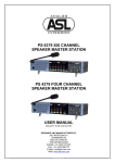


![User Manual PS 430 [ASL]](http://vs1.manualzilla.com/store/data/005676322_1-235f4942ab78942bc49f054c2ec420ac-150x150.png)