1
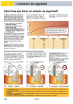
EP.V.10367 · 09/2015
EP.V. 10367
10/2013
USER MANUAL
Safety storage cabinets (EN 14470-1 &
EN 14470-2)
5 JAHRE GARANTIE*
* Bei Abschluss eines BASICPlusVertrages, mit fester 5-jähriger
Laufzeit, genießen Sie 5 Jahre
Garantie für Ihren Sicherheitsschrank.
10 JAHRE GARANTIE*
* Bei jährlicher Beauftragung des
Premium Q-Tarifs verlängert sich
die Garantie für Ihren Q-LINE
Sicherheitsschrank auf bis zu 10 Jahre.
5 YEARS WARRANTY*
*Upon conclusion of an asecos service and maintenance agreement
(BasicPlus tariff) with a fixed
term of 5 years, you will get a warranty extension for a maximum of 5
years for your safety storage cabinet.
10 YEARS WARRANTY*
* Upon conclusion of an asecos
service and maintenance agreement
(PREMIUM Q tariff), you will get
a warranty extension for up to 10 years for
your Q-LINE safety storage cabinet.
Weitere Informationen zu unseren Garantieleistungen finden Sie unter
www.asecos.com/service-leistungen
For detailed information about our warranties please visit
www.asecos.com/service-conditions
1 1
S-CLASSIC-15
S15.197.120
S15.197.060
S15.197.060.R
S-CLASSIC-30
S30.197.120
S30.197.060
S30.197.060.R
S-CLASSIC-60
S60.196.120
S60.196.060
S60.196.060.R
S-CLASSIC-90
S90.196.120
S90.196.120.MV
S90.196.090
S90.196.060
S90.196.060.R
S90.129.120
S90.129.060
S90.129.060.R
S90.196.120.WDAS
S90.196.120.MV.WDAS
S90.196.090.WDAS
S90.196.060.WDAS
S90.196.060.WDASR
S90.129.120.WDAS
S90.129.060.WDAS
S90.129.060.WDASR
S-PEGASUS-90
S90.196.120.WDEU
S90.196.090.WDEU
S90.129.120.WDEU
S90.196.120.WDAC
S90.196.120.MV.WDAC
S90.196.090.WDAC
S90.196.060.WDAC
S90.196.060.WDACR
S90.129.120.WDAC
S90.129.060.WDAC
S90.129.060.WDACR
S-PHOENIX-30
S90.197.120.FDAS
S90.197.060.FDAS
S90.197.060.FDASR
S-PHOENIX-90
S90.196.120.FDAS
S90.196.120.MV.FDAS
S90.196.090.FDAS
S90.196.060.FDAS
S90.196.060.FDASR
S90.196.060.075.FDAS
S90.196.060.075.FDASR
S-PHOENIX Vol.2-90
S90.196.120.FDEU
S90.196.120.FDAC
S90.196.120.MV.FDAC
S90.196.060.FDAC
S90.196.060.FDACR
S90.196.060.075.FDAC
S90.196.060.075.FDACR
S-PHOENIX touchless-90
S90.196.120.FDAO
S90.196.060.FDAO
S90.196.060.075.FDAO
Q-CLASSIC-15
Q15.195.116
Q15.195.056
Q15.195.056.R
Q-CLASSIC-30
Q30.195.116
Q30.195.086
Q30.195.056
Q30.195.056.R
Q-CLASSIC-90
Q90.195.120
Q90.195.090
Q90.195.060
Q90.195.060.R
Q-PEGASUS-90
Q90.195.120.WDAC
Q90.195.090.WDAC
Q90.195.060.WDAC
Q90.195.060.WDACR
Q-PHOENIX-90
Q90.195.120.FD
UB-T-30
UB30.060.110.2T
UB-S-30
UB30.060.140.2S
UB30.060.110.2S
UB30.060.110.S
UB-S-90K
UB90.060.110.KU.S
UB-S-90
UB90.060.140.2S
UB90.060.140.050.2S
UB90.060.110.S
UB90.060.110.050.S
UB90.060.110.2S
UB90.060.110.050.2S
UB90.060.089.S
UB90.060.089.050.S
UB90.060.059.S
UB90.060.059.050.S
UB-T-90
UB90.060.110.2T
UB90.060.110.050.2T
UB90.080.110.075.2T
UB90.060.089.2T
UB90.060.089.050.2T
UB90.060.059.T
UB90.060.059.TR
UB90.060.059.050.T
UB90.060.059.050.TR
UB-ST-90
UB90.060.140.S2T
UB90.060.140.050.S2T
UB90.060.110.ST
UB90.060.110.050.ST
K-PHOENIX-30
K30.197.120.MV.FWAS
K30.197.120.MC.FWAS
K-CLASSIC-90
K90.196.120.MV.WDAS
K90.196.060.MH.WDAS
K-PHOENIX-90
K90.196.120.MF.FWAS
K90.196.120.MC.FWAS
K90.196.120.MV.FDAS
K90.196.060.MH.FDAS
K-PHOENIX Vol. 2-90
K90.196.120.MF.FWAC
K90.196.120.MC.FWDAC
K-UB-90
K90.060.140.050.UB.ST
K90.060.140.050.UB.3T
K90.060.110.050.UB.ST
K90.060.110.050.UB.2T
XL-CLASSIC-90
XL90.222.155.WDAS
XL90.222.110.WDAS
G-CLASSIC-30
G30.205.140
G30.205.120
G30.205.090
G30.205.060
G30.205.060.R
G-ULTIMATE-90
G90.205.140
G90.205.120
G90.205.090
G90.205.060
G90.205.060.R
G90.205.060.2F
G90.205.060.2F.R
G90.145.060
G90.145.060.R
asecos GmbH
Abt. Kundendienst
Weiherfeldsiedlung 16–18
D-63584 Gründau
Fax: +49 60 51 – 92 20-10
IHRE PERSÖNLICHE DOKUMENTATION ZUM asecos-SICHERHEITSSCHR ANK
Sehr geehrte Kundin, sehr geehrter Kunde,
mit dem Kauf Ihres asecos-Sicherheitsschrankes haben Sie eine entscheidende Investition für
die Sicherheit in Ihrem Haus getätigt. Vor Ihnen steht ein innovatives Produkt aus hochwertigen
Materialien, das höchste Qualität garantiert.
Sicherheitsschränke aus dem Hause asecos verfügen über eine lückenlose Zulassungs-Dokumentation. Wir archivieren Ihre Zulassungsdokumente jedes einzelnen Schrankes für Sie, bis Sie diese
im Bedarfsfall (z. B. einer Betriebsbegehung o. ä.) mit diesem Formular von uns anfordern.
Dazu einfach dieses Formular heraustrennen/kopieren und mit Ihrer Adresse und der Seriennummer des Schrankes versehen per Fax zurück an uns.
Mit freundlichen Grüßen
asecos GmbH
YOUR PERSONAL DOCUMENTATION TO THE asecos SAFET Y CABINET
Dear Customer,
you have made a decisive investment in safety for your company by purchasing this asecos safety
storage cabinet. You now own an innovative product made of top-quality materials guaranteeing
the highest quality standards.
asecos safety storage cabinets have complete authorisation documents. We archive the authorisation documents for every individual cabinet, keeping them ready for you should you ever need
them (e.g. for a works inspection or similar). Simply request them using this form.
Tear off or copy that page and return to us by fax with your address and serial number of the
cabinet on it.
Yours sincerely
asecos GmbH
Firma • company
Abteilung • department
Name • name
Straße • street
PLZ • postal code
Ort • city
Schrank • cabinet
Seriennummer(n) • serial number(s)
4 4
OPER ATING INSTRUCTIONS
Dear customer,
Thank you very much for purchasing a safety storage cabinet from our company, with which you
have made a decisive investment in the safety within your company.
Our safety storage cabinets make the storage of hazardous materials at the workplace safe and
convenient for you.
Please read these operating instructions very carefully. Get to know the advantages and simple
operability of our safety storage cabinets in detail.
This simplifies the daily handling of hazardous materials for you.
EN
Many thanks.
Your asecos team
TABLE OF CONTENTS
1. NOTES • GUIDELINES • GUARANTEE . . . . . . . . . . . . . . . . . . . . . . . . . . . . . . . . . . . . . . . . . . . . . . 6
1.1.
General safety notes. . . . . . . . . . . . . . . . . . . . . . . . . . . . . . . . . . . . . . . . . . . . . . . . 6
1.2.Guarantee. . . . . . . . . . . . . . . . . . . . . . . . . . . . . . . . . . . . . . . . . . . . . . . . . . . . . . . . . 6
1.3.
Cabinet details. . . . . . . . . . . . . . . . . . . . . . . . . . . . . . . . . . . . . . . . . . . . . . . . . . . . . 6
2.TRANSPORT. . . . . . . . . . . . . . . . . . . . . . . . . . . . . . . . . . . . . . . . . . . . . . . . . . . . . . . . . . . . . . . . . . 7
3. ERECTION • COMMISSIONING • FUNCTION . . . . . . . . . . . . . . . . . . . . . . . . . . . . . . . . . . . . . . . . 8
3.1.
Alignment of the cabinets. . . . . . . . . . . . . . . . . . . . . . . . . . . . . . . . . . . . . . . . . . . . 8
3.2.Commissioning. . . . . . . . . . . . . . . . . . . . . . . . . . . . . . . . . . . . . . . . . . . . . . . . . . . . 10
3.3.
Anti-tilt device . . . . . . . . . . . . . . . . . . . . . . . . . . . . . . . . . . . . . . . . . . . . . . . . . . . . 10
4. CLOSING MECHANISMS . . . . . . . . . . . . . . . . . . . . . . . . . . . . . . . . . . . . . . . . . . . . . . . . . . . . . . . 10
4.1.
Types of closing. . . . . . . . . . . . . . . . . . . . . . . . . . . . . . . . . . . . . . . . . . . . . . . . . . . 10
4.2.
Automatic door closing system: TSA. . . . . . . . . . . . . . . . . . . . . . . . . . . . . . . . . . . 11
4.3.Locking. . . . . . . . . . . . . . . . . . . . . . . . . . . . . . . . . . . . . . . . . . . . . . . . . . . . . . . . . . 12
5. INTERIOR FIT TINGS: S-LINE • Q-LINE • K-LINE • XL-LINE • UB-LINE . . . . . . . . . . . . . . . . . . . . 13
5.1.Spill containment sump. . . . . . . . . . . . . . . . . . . . . . . . . . . . . . . . . . . . . . . . . . . . . 13
5.2.
Drawers, second storage level. . . . . . . . . . . . . . . . . . . . . . . . . . . . . . . . . . . . . . . . 13
5.3.
tray shelves (height-adjustable) . . . . . . . . . . . . . . . . . . . . . . . . . . . . . . . . . . . . . . 14
5.4.
Shelves (height-adjustable). . . . . . . . . . . . . . . . . . . . . . . . . . . . . . . . . . . . . . . . . . 14
6. INTERIOR FIT TINGS: G-CLASSIC-30 • G-ULTIMATE-90. . . . . . . . . . . . . . . . . . . . . . . . . . . . . . . 14
6.1.
Mounting rails. . . . . . . . . . . . . . . . . . . . . . . . . . . . . . . . . . . . . . . . . . . . . . . . . . . . . 14
6.2.
Cylinder retainer . . . . . . . . . . . . . . . . . . . . . . . . . . . . . . . . . . . . . . . . . . . . . . . . . . 14
6.3.
Rolling ramp. . . . . . . . . . . . . . . . . . . . . . . . . . . . . . . . . . . . . . . . . . . . . . . . . . . . . . 15
6.4.
Pipe / cable leadthrough. . . . . . . . . . . . . . . . . . . . . . . . . . . . . . . . . . . . . . . . . . . . 15
6.5.
Ermeto screw connection . . . . . . . . . . . . . . . . . . . . . . . . . . . . . . . . . . . . . . . . . . . 15
6.6.
Optional equipment: G-CLASSIC-30 • G-ULTIMATE-90. . . . . . . . . . . . . . . . . . . . 16
7.STORAGE . . . . . . . . . . . . . . . . . . . . . . . . . . . . . . . . . . . . . . . . . . . . . . . . . . . . . . . . . . . . . . . . . . . 16
8.EARTHING. . . . . . . . . . . . . . . . . . . . . . . . . . . . . . . . . . . . . . . . . . . . . . . . . . . . . . . . . . . . . . . . . . 16
9.VENTILATION. . . . . . . . . . . . . . . . . . . . . . . . . . . . . . . . . . . . . . . . . . . . . . . . . . . . . . . . . . . . . . . . 17
9.1.
General facts . . . . . . . . . . . . . . . . . . . . . . . . . . . . . . . . . . . . . . . . . . . . . . . . . . . . . 17
9.2.
S-LINE • Q-LINE • K-LINE • XL-LINE • UB-LINE. . . . . . . . . . . . . . . . . . . . . . . . . . . . 17
9.3.
G-CLASSIC-30 • G-ULTIMATE-90. . . . . . . . . . . . . . . . . . . . . . . . . . . . . . . . . . . . . . 18
9.4.
Montage of Fire protection sleeve. . . . . . . . . . . . . . . . . . . . . . . . . . . . . . . . . . . . . 18
10.FIRE • DISPOSAL . . . . . . . . . . . . . . . . . . . . . . . . . . . . . . . . . . . . . . . . . . . . . . . . . . . . . . . . . . . . . 18
10.1. Opening the cabinet after the fire. . . . . . . . . . . . . . . . . . . . . . . . . . . . . . . . . . . . . 18
10.2.Disposal . . . . . . . . . . . . . . . . . . . . . . . . . . . . . . . . . . . . . . . . . . . . . . . . . . . . . . . . . 19
11.SAFET Y CHECKS. . . . . . . . . . . . . . . . . . . . . . . . . . . . . . . . . . . . . . . . . . . . . . . . . . . . . . . . . . . . . . 19
5 5
1.NOTES • GUIDELINES • GUARANTEE
1.1. GENERAL SAFETY NOTES
•Observe applicable statutes and regulations, and the notes in these operating instructions, when
handling hazardous materials.
•Work on the electrical system is to be carried out only with the power turned off and only by
qualified electricians – refer here to the regulations of the local electricity supply company.
•The on-site installation conditions are to be observed (e.g. bolting the cabinets to the building).
•The instructions of the supervisory engineering department must be followed.
•Observe accident prevention regulations and workplace ordinance.
•Ensure that the necessary safety checks are only carried out by authorised staff using original spare
parts.
•Only use the cabinet after having been properly instructed; access is to be forbidden to
unauthorised persons.
•The pivoting area of the doors is to be kept free at all times; doors/drawers are to be kept closed.
•By assigning trained/authorised technical personnel you can prevent the malfunctions, damage
and corrosion damage that result from inappropriate transport.
•Observe the upper limits for stored quantities, loading etc.
•Containers with a volume larger than that of the spill containment sump may not be placed
inside the cabinet; spilt hazardous materials are to be collected immediately and removed.
•Vessels containing aggressive chemicals (acids/alkalis) are to be kept in special cabinets for acids and
alkalis or on shelves for acids and alkalis as well as in cabinets with metal-free interior equipment.
•Sufficient technical ventilation must be ensured , pay attention to the notices on connection to
an extraction system under point 9.1!
•Before storing such materials, check that the cabinet's surface is resistant to the chemicals.
•The storage of corrosive liquids or gases can affect the function of the shut-off equipment for the
air supply and exhaust.
•Before the initial commissioning, the safety storage cabinet is to be examined by the user for
possible damage. (See point 3.2)
Set-up requirements
0–35 °C
30–70 %
1.2. GUARANTEE
The guarantee for this product is agreed between you (the customer) and your dealer
(the seller). As the manufacturer, asecos guarantees the products listed in the operating instructions for a period of 24 months from the date of delivery.
All model safety equipment are subject to a compulsory annual inspection by specialised staff
authorised by the manufacturer. Otherwise the customer’s guarantee claim against the
manufacturer expires.
1.3. CABINET DETAILS
A complete overview of the models can be found at the start of the operating instructions.
Cabinet data Technical drawing
Technical data Logbook (included with the cabinet)
Appenidix 1
Table in Appendix 2
S-LINE • Q-LINE • UB-LINE • XL-LINE • K-LINE
These models are tested, certified and marked according to requirements of BS EN 14470-1.
They are intended for the storage of combustible liquids in work rooms in accordance with the
valid national regulations.
G-CLASSIC-30 • G-ULTIMATE-90
These models are tested, certified and marked according to requirements of BS EN 14470-2.
They are intended for the storage and emptying of gas cylinders in buildings in accordance with
the valid national regulations.
6 6
2.TRANSPORT
GENERAL
CAUTION:
Transport the cabinet in an upright position on a pallet truck, tied and secured against slipping, until
the final place of installation is reached.
The transport locks in the door joints may only be removed directly at the place of installation!
Inappropriate transport can lead to concealed damage to the fire protection insulation!
We can only guarantee the necessary quality if the cabinet is transported to the place of its use by our
specially trained staff.
EN
Tilting the cabinet (may only be done without jolts)
Q-LINE
Dismantling of the transport packaging
= 4×
1
2
4
5
= 8×
3
ATTENTION
Q-LINE type 90,
width 600 mm
The clearance drive-in width
of the base is 520 mm.
Q-LINE type 15/30,
width 560 mm
The clearance drive-in width
of the base is 406 mm.
6
In-plant transport
•is also possible without transport locks (inserted as standard in the door joints)
You must observe this when
selecting a pallet truck!
Appliances with a carrying
width larger than the drivein width may not be used.
= 4×
1
2
3
Titling onto the side wall
•is only possible with the optionally available tilting bracket (order no. HF.V.27665)
1
2
3
7 7
Q-Mover
•Order no. HF.I.23526, available from your authorised dealer
= 4×
1
a:upright transport
2
b:upright transport through standard doors
(headroom 1986 ± 2mm)
3
CAUTION:
Written notification
of any damage to
the cabinet must
be given immediatly!
4
XL-LINE
5
= 8×
4
5
3
6
CAUTION:
Afterwards, lower the cabinet slowly and
without jolts in order to prevent damage!
= 5×
Remove the transport locks from the door joints after erection!
7
3.ERECTION • COMMISSIONING • FUNCTION
3.1. ALIGNMENT OF THE CABINETS
GENERAL
8 8
CAUTION:
Door elements must not scrape against the fire prevention seals in the fold of the door when opening
and closing! Doors with an automatic closing mechanism must close automatically from every position
and the lock must be able to lock!
The distance between the door and the floor can be reduced to less than 40 mm. The door panels
required for this can be obtained on enquiry from asecos service.
S-LINE 60/90
K-PHOENIX-30/-90/VOL. 2-90
K-CLASSIC-90
XL-LINE
G-CLASSIC-30
G-ULTIMATE-90
1 EN
S-PHOENIX touchless-90
1 Unlock the cabinet and open it manually
2 Remove the power cable from the interior
3 Align the cabinet
4 Allow the cabinet to close automatically
Q-CLASSIC-90
Q-PEGASUS-90
Q-PHOENIX-90
4×
4×
max. 2× (!)
2
3
max. 2× (!)
2
3
Q-CLASSIC-15/30
with adjusting aids in plinth
with plinth:
UB-LINE
K-UB-90
S-PHOENIX-30
Q-CLASSIC-15/30 without
adjusting aids
without plinth: UB-LINE, K-UB-90
made of
metal!
9 9
3.2. COMMISSIONING
S-PHOENIX touchless-90
•Before putting into operation for the first time, the user must carry out an examination of the
safety storage cabinet for possible damage, such as defective or loose sealing elements, correct
alignment and perfect functioning of the door elements.
•Use the cabinet and accessories only if they are in an orderly condition.
Connection to the power supply
•Accessories: 5 m low-temperature IEC power cable including earthed mains plug
3.3. ANTI-TILT DEVICE
Q-CLASSIC-15
Q-CLASSIC-30
CAUTION:
If these model groups are equipped with drawers, they must be fastened to the wall using the
anti-tilt device supplied.
Anti-tilt bracket (EP.ML.6323: Optional to prevent tilting with maximum load and fully extended drawers
4.CLOSING MECHANISMS
4.1. TYPES OF CLOSING
1 Thermal release: in the case of fire the doors close automatically (even if latched)
2 Automatic door closing system TSA 3 Doors permanently self-closing
4 Doors with arrest system
5 Doors closable only by hand
1010
1
Q-LINE
Q-CLASSIC-15 / -30
3
3
3
Q-CLASSIC-90
Q-PEGASUS-90
S-LINE
S-CLASSIC-15 / -30 / -60 / -90
S-PHOENIX-90
S-PEGASUS-90 / S-PHOENIX Vol. 2-90
S-PHOENIX touchless-90
K-PHOENIX-30
K-CLASSIC-90
K-PHOENIX-90
K90.196.120(060).MV(MH).FDAS
K-PHOENIX Vol. 2-90
K-UB-90
UB-LINE
UB30.060.110.2TAS
ALL MODELS
XL-LINE
ALL MODELS
G-LINE
G-CLASSIC-30 / G-ULTIMATE-90
3
3
3
3
3
3
3
S-PHOENIX-30
K-LINE
2
3
3
5
4
3
3
3
3
3
3
optional
3
3
3
3
EN
VBFacid/base
VBFacid/base
VBFacid/base
VBFacid/base
VBFacid/base
compartement compartement compartement compartement compartement compartement compartement compartement compartement compartement
3
3
3
3
3
3
3
3
3
3
3
3
3
3
3
3
3
3
3
3
3
3
3
3
3
3
3
3
3
3
3
3
3
3
Q-CLASSIC-15/-30/-90 • UB-LINE • K-UB-90 (VBF-compartement):
If the doors not longer latch in any position, then the fusible link of the thermal release has tripped.
The cabinet is to be returned to its delivery condition immediately in order to avoid malfunctions.
4.2. AUTOMATIC DOOR CLOSING SYSTEM: TSA
CAUTION:
The doors close automatically. The time interval until the doors close can be set individually by means
of a jumper (preset: 60 seconds).
Do not push the doors to close by hand, since this can lead to damage to the mechanism!
Sequence
11 11
Battery replacement
=4×
4
=4×
5
=4×
3
6
3
Changing the closing times with the aid of the jumper
1: 15 sec
2: 60 sec
3: 4.5 min
CAUTION:
The electrical cable on the housing may not come into contact with the locking linkage of the cabinet!
S-PHOENIX touchless-90
Closing process
Entering the sensor range during the closing movement
CAUTION:
The closing of the doors takes place purely mechanically and only with the very low forces of the
closing spring. Reaching inside the cabinet during the closing process is therefore harmless and the
risk of injury is ruled out.
4.3. LOCKING
CAUTION:
Applicable for all models: The owner/user must ensure that all doors and drawers are kept closed
whenever the contents of the cabinet are not being accessed! In general it must be noted that the
cabinets do not possess an emergency unlocking facility. This means that persons trapped inside the
cabinet cannot free themselves!
1212
SAFETY CYLINDER
with locking status indicator
Q-LINE
S-LINE
K-LINE
S-CLASSIC-15/30
S-PHOENIX-30
Q-CLASSIC-90
Q-PEGASUS-90
K-PHOENIX-90 :
K90.196.120.MV.FDAS
K90.196.060.MH.FDAS
K90.196.120.MF.FWAS (Fire-comp.)
K90.196.120.MC.FWAS (Fire-comp.)
K-PHOENIX-90 (acid/base-comp.):
K90.196.120.MF.FWAS
K90.196.120.MC.FWAS
K-PHOENIX Vol. 2-90 (a/b-comp.)
UB-LINE
XL-LINE XL-CLASSIC-90
G-LINE
Q-CLASSIC-15/-30
S-CLASSIC-60/90
S-PEGASUS-90
S-PHOENIX-90/Vol. 2-90/touchless-90
K-CLASSIC-90
K-UB-90
K-PHOENIX-30
CYLINDER LOCK (suitable for master key systems)
with locking status indicator
ALL MODELS
EN
K-PHOENIX Vol. 2-90 (Fire-comp.)
G-CLASSIC-30 • G-ULTIMATE-90
5.INTERIOR FITTINGS: S-LINE • Q-LINE • K-LINE • XL-LINE • UB-LINE
CAUTION:
Loose parts (e.g. insertable sumps) must always be fully installed/inserted in order to ensure secure
closing of the cabinet doors in case of fire.
5.1. SPILL CONTAINMENT SUMP
1
2
According to EN 14470-1: A spill containment sump must be
installed below the lowest storage level. The spill containment sump
must be able to hold a minimum volume of 10 % of all the containers stored in the cabinet 1 or at least 110 % of the volume of the
largest single container 2 , whichever of these volumes is larger.
Use as a storage surface in case of cabinets with several storage levels:
CAUTION:
Use as a storage surface is possible only in
conjunction with a perforated metal plate insert
Leaks:
•Liquid in the sump is to be collected using suitable means.
•The choice of means is your own responsibility.
1
2
3
5.2. DRAWERS, SECOND STORAGE LEVEL
•All drawers have been designed in such a way that they are permanently drawn in the cabinet or
automatically drawn into the cabinet in the case of fire, making it possible to close the cabinet doors.
CAUTION:
The height of the drawers in safety storage cabinets may be adjusted only by authorised asecos
employees, since the safe retraction of the drawers in case of fire must be guaranteed!
13 13
5.3. TRAY SHELVES (HEIGHT-ADJUSTABLE)
4
5
5.4. SHELVES (HEIGHT-ADJUSTABLE)
6.INTERIOR FITTINGS: G-CLASSIC-30 • G-ULTIMATE-90
6.1. MOUNTING RAILS
•for fittings for pressurised gases, height-adjustable
6.2. CYLINDER RETAINER
A G-ULTIMATE-90
B G-CLASSIC-30
a permanently mounted on
the rear wall
b tension belts for securing
the gas cylinders
A
B
c adjustable in depth
(G-ULTIMATE-90)
Adjustable in depth with G-ULTIMATE-90
1
1414
2
3
6.3. ROLLING RAMP
•latches automatically in the folded condition
STANDARD
2
COMFORT
EN
6.4. PIPE / CABLE LEADTHROUGH
•prepared on top section
The pipe/cable can now be
fed in without further insulation measures.
CAUTION:
The max. permissible lead-through diameters in accordance with BS EN 14470-2 (10 mm for pipes,
20 mm for cables) are to be observed!
All unused holes in the cabinet wall must be properly sealed with suitable fire protection putty (ROKU
1000, order no. 6520) over the full area and the complete wall thickness.
It is recommendable to manufacture the pipes from rustproof stainless steel or a material with similar
conductive properties in order to maintain the fire resistance characteristics established and specified
during the test.
6.5. ERMETO SCREW CONNECTION
•prepared on top section
•Thanks to the R3/8” internal threads a conventional ermeto screw connection can be mounted
in the second step.
15 15
6.6. OPTIONAL EQUIPMENT: G-CLASSIC-30 • G-ULTIMATE-90
SIDE CYLINDER RETAINER
(adjustable without tools)
•is hooked into a mounting rail and is adjustable in height
SIDE CYLINDER RETAINER
(bolted)
•is adjustable in height and bolted to the side wall
= 4 mm
= 20 mm
7.STORAGE
S-LINE
Q-LINE
K-LINE
XL-LINE
UB-LINE
•Vessels containing aggressive chemicals (acids and alkalis) are to be kept in special cabinets
for acids and alkalis or on shelves for acids and alkalis as well as in safety storage cabinets with
metal-free interior equipment.
•The storage of corrosive liquids can affect the function of the shut-off equipment for the air
supply and exhaust.
•Each container placed inside reduces the minimum containment volume demanded in section
5.1. in relation to the total stored quantity.
G-CLASSIC-30
G-ULTIMATE-90
•The total volume of the stored gas cylinders must not exceed 210 l + 10 l (purging gas cylinder).
Applicable for all models:
Depending on the type class of the cabinet, observe the respective valid national regulations!
8.EARTHING
An earth connection may be necessary, depending on the customer-specific use of
the safety storage cabinet. The decision regarding this is taken on the basis of a risk
analysis by the customer.
OVERVIEW
1616
1
2
3
4
5
6
Rear section: UB-LINE | K-UB-90
Rear section: XL-LINE
Top section: Q-LINE
Top section: S-LINE 15/30 Minuten | K-LINE
Top section: S-LINE 60/90 Minuten | K-LINE
Top section: G-CLASSIC-30 | G-ULTIMATE-90
The spare parts required for the connection are
not part of the scope of supply.
EN
Earthing when decanting:
Connection to a potential equalisation system is compulsory in this case.
Cabinets in which decanting can be performed should additionally be equipped with an earth terminal
in the interior (at a surcharge on enquiry) which must be connected to the decanting containers. This
is standard with cabinets from the UB-LINE with drawers.
9.VENTILATION
9.1. GENERAL FACTS
NOTICES
The fire protection valves near the supply and extraction air connections are safety
and maintenance-relevant components.
In order to check the correct operation or to replace a defective element, please ensure
that flexible connecting hoses or sliding pieces are used to connect to an extraction
system in order to ensure simple dismounting and re-mounting of the extraction air
connection.
•If installed on an exhaust system, a check must be carried out to ensure proper connection to
the system (e.g. using a smoke tube)
Q-CLASSIC-90
Q-PEGASUS-90
Ventilation wheel for technical ventilation
•The ventilation wheel serves as an indicator for correct ventilation.
•If the wheel turns, the necessary 10-fold air recirculation rate is
exceeded.
S-LINE
Q-LINE
K-LINE
XL-LINE
G-LINE
DN
75
<01/2014
UB-LINE
K-UB-90
DN 75
>01/2014
UB-LINE
K-UB-90
DN 50
17 17
9.2. S-LINE • Q-LINE • K-LINE • XL-LINE • UB-LINE
•All models can be connected to a technical exhaust system via the exhaust connector. Please see
the respectively applicable national regulations for the specified air recirculation rate, maximum
pressure losses and exhaust air ducts.
CAUTION:
In general these models can be operated without technical ventilation. The direct environment of the
cabinet can be an explosive zone in this case. If the cabinet is to be operated without an exhaust connection, the user must attach a marking to it. With some models the supply and exhaust connectors
are not pre-mounted. They are included with the cabinet and must be screwed to the openings on the
top section.
UB-LINE
K-UB-90
EXHAUST AIR (a)
SUPPLY AIR (b):
2 with plinth
3 without plinth
9.3. G-CLASSIC-30 • G-ULTIMATE-90
CAUTION:
In the case of gas cylinder cabinets that are connected to a technical exhaust system, the minimum air
recirculation rate must be fulfilled according to BS EN 14470-2.
The ventilation must be permanent in operation and must lead out to a safe place in the open air.
The pressure drop of the cabinet must not exceed 150 Pa. The inflow velocity of the air must
be at least 20 cm/s.
Minimum air recirculation rate during storage of:
combustible/oxidising gases
toxic gases
9.4. MONTAGE OF FIRE PROTECTION SLEEVE
FOR MODELS:
G90.205.140
G90.205.120
G30.205.140
G30.205.120
4×
(4×30 mm)
(5×25 mm)
10.FIRE • DISPOSAL
10.1. OPENING THE CABINET AFTER THE FIRE
1818
4×
4×
(5×25 mm)
CAUTION:
Depending upon the duration of the fire an ignitable vapour/air mixture may have formed; therefore
remove all sources of ignition within a 10 metre radius of the cabinet before opening it.
¡ use only spark-free tools
¡ open the cabinets with extreme caution
EN
10.2. DISPOSAL
The models can be disposed of once they have
been dismantled and the materials sorted. They
are free from materials that have to be disposed of as special waste.
11. SAFETY CHECKS
As safety equipment the cabinets have to be checked for safety at least once per year.
The next checking date can be taken from the check sticker on the outside of the door. This annual
check can be carried out with the necessary care, and for securing your warranty claims in the case
of fire, only by an authorised asecos employee (refer also to our service brochure regarding this).
In addition, we recommend that you carry out a daily and monthly functional check:
Daily functional check
•applies to the spill containment sumps (collect and remove any leakages)
monthly functional check
•perfect function of the doors:
- - hinges
- - locking system
- - door closer
- - door open arrest system
•correct seating and condition of the fire protection seals
In case of damage please contact your dealer in order to have the cabinet repaired using original
spare parts. The cabinets can be cleaned with a mild household cleaner and a soft cloth.
CONTACT:
In the case of defects or complaints about our products (within and also after the
warranty period), and for requesting safety checks or taking out a service contract,
please contact our service hotline on:
Tel: +44 1785 22 70-90 [email protected]
19 19
2020
ANEXO 1: DESENHO TÉCNICO
Abluft ∅75
243
(160.5)
Zuluft ∅75
Abluft ∅75
Q90.195.120
Q90.195.120.WDAC
Q90.195.090
Q90.195.090.WDAC
Q90.195.060 | Q90.195.060.WDAC
Q90.195.060.R | Q90.195.060.WDACR
Q-CL ASSIC-90•Q-PEGASUS-90
Zuluft ∅75
160.5
(160.5)
Q-CL ASSIC-90•Q-PEGASUS-90
Abluft ∅75
543
158
Q-CL ASSIC-30
158
Zuluft ∅75
160.5
158
(160.5)
843
Q15.195.056 | Q15.195.056.R
Q30.195.056 | Q30.195.056.R
Q-CL ASSIC-90•Q-PEGASUS-90
Q-CL ASSIC-15/-30
160.5
Q30.195.086
Q30.195.086.R
Q-CL ASSIC-15/-30
Q15.195.116
Q30.195.116
Q-LINE
Abluft=Exaustãodear•zuluft=Fornecimentodear
S-LINE
Q90.195.120.FD
S-CL ASSIC-15•S-CL ASSIC-30
S60.196.120(.WDAS)
S90.196.120(.WDAS)
S90.196.120.WDAC/WDEU
S90.129.120(.WDAS)
S90.129.120 .WDAC/WDEU
S90.196.120.MV(.WDAS/WDAC)
S60.196.060(.WDAS)
S90.196.060(.WDAS/WDAC)
S90.129.060(.WDAS/WDAC)
S-CL ASSIC-60/-90•S-PEGASUS-90
94
°
S-CL ASSIC-60/-90•S-PEGASUS-90
S15.197.060(.WDAS)
S30.197.060(.WDAS)
934.52
155.52
Erdungsmöglichkeit
°
94
S-CL ASSIC-15•S-CL ASSIC-30
154.88
Abluft Ø 75
Zuluft
942.76
Q-PHOENIX-90
884
S15.197.120(.WDAS)
S30.197.120(.WDAS)
1
21 21
S-CL ASSIC-90•S-PEGASUS-90
S-PHOENIX-30
S-PHOENIX-90•S-PHOENIX-Vol.2-90
S-HOENIXtouchless-90
S90.196.090.FDAS
S90.196.060.FDAS(FDAC/FDAO)
S90.196.060.075.FDAS(FDAC/FDAO)
S-PHOENIX-90
K-CL ASSIC-90•K-PHOENIX-90
K90.196.060.MH.WDAS(FDAS)
K-CL ASSIC-90•K-PHOENIX-90
K-PHOENIXVol.2-90
K90.196.120.MV.WDAS(FDAS)
K90.196.120.MF.FWAS | K90.196.120.MC.FWAS
K90.196.MF.FWAC | K90.196.120.MC.FWDAC)
K90.060.140.050.UB.ST
K90.060.140.050.UB.3T
K90.060.110.050.UB.ST
K90.060.110.050.UB.2T
181
300
740
179
Erdung
Abluft ∅50
601
Zuluft
30
Erdung
K-UB-90
921.42
Abluft ∅50
601
K-UB-90
181
30
K-CL ASSIC-90•K-PHOENIX-90
2222
K30.197.120.MV.FWAS
K30.197.120.MC.FWAS
K-PHOENIX-30
K-LINE
S-PHOENIX-90•S-PHOENIX-Vol.2-90
S-HOENIXtouchless-90
S90.196.120.FDAS(FDEU/FDAC/FDAO)
S90.196.120.MV.FDAS(FDAC)
S-PHOENIX-90•S-PHOENIX-Vol.2-90
S-HOENIXtouchless-90
S30.197.120.FDAS
S90.196.090(.WDAS/WDAC/WDEU)
Zuluft
XL90.222.110.WDAS
UB30.060.140.2S
UB90.060.140.2S
UB90.060.050.140.2S
UB90.060.140.S2T
UB90.060.050.140.S2T
Erdung
Abluft ∅50
Zuluft
UB90.060.089.S | UB90.060.089.050.S
UB90.060.089.2T | UB90.060.089.050.2T
UB30.060.110.2T | UB30.060.110.2TAS
UB30.060.110.2S | UB30.060.110.S
UB90.060.110.S | UB90.060.110.050.S
UB-S-30/-90•UB-T-30/-90•UB-ST-90
UB-S-30•UB-S-90•UB-ST-90
UB-LINE
XL-CL ASSIC-90
XL90.222.155.WDAS
XL-CL ASSIC-90
XL-LINE
UB90.060.110.2S | UB90.060.110.050.2S
UB90.060.110.2T | UB90.060.110.050.2T
UB90.060.110.ST | UB90.060.110.050.ST
Erdung
Abluft ∅50
Zuluft
UB90.060.059.T | UB90.060.059.TR
UB90.060.059.050.T | UB90.060.059.050.TR
UB90.060.059.S | UB90.060.059.050.S
UB90.080.110.075.2T
Zuluft
Erdung
Abluft ∅50
Zuluft
UB-T-90
Abluft ∅50
UB-S-90•UB-ST-90
UB-S-90•UB-ST-90
Erdung
Erdung
Abluft ∅50
1
Zuluft
23 23
2424
G-ULTIMATE-90
G90.205.120
G90.205.090
G90.205.060 | G90.205.060.R
G90.205.060.2F | G90.205.060.2F.R
G90.145.060 | G90.145.060.R
G-ULTIMATE-90
G90.205.140
G-CL ASSIC-30
G30.205.060 | G30.205.060.R
G-ULTIMATE-90
G-CL ASSIC-30
G30.205.090
G-ULTIMATE-90
G30.205.120
G-CL ASSIC-30
G30.205.140
G-CL ASSIC-30
G-LINE
ANEXO 2: CARACTERÍSTICAS TÉCNICAS
Legende für Tabelle „Technische Daten“
Key for “Technical data” table
Legende voor tabel „Technische gegevens“
Légende du tableau « Caractéristiques techniques »
Leyenda de la tabla “Datos técnicos“
Legenda per tabella "Dati tecnici"
Legenda para a tabela "Dados técnicos"
DE
EN
NL
FR
ES
IT
PT
Abmessungen
Dimensions
Afmetingen
Dimensions
Dimensiones
Dimensioni
Dimensões
Typklasse
Type-Classification
Typeklasse
Type de classe
Clase tipo
Classe del tipo
Tipo de classe
Leergewicht gesamt Net Weight
Leeggewicht totaal
Poids total à vide
Peso en vacío total
Peso a vuoto
completo
Peso total em vazio
Max. Belastung
max. Load Cabinet
max. belading
Chargement max.
Carga máx
Carico max.
Carga máx.
Flächenlast
Area Load
Oppervlaktebelasting Charge superficielle
Carga superficial
Carico specifico
Carga da superfície
Max. Belastung
Fachboden
max. Load Shelf
max. belasting
opvanglegbord
Charge max.
d’étagère
Carga máx. bandeja
Carico max. ripiano
fisso
Carga máx. da
prateleira
Max. Belastung
Auszug
max. Load Drawer
max. belasting
schuiflade
Charge max. de tiroir Carga máx. cajón
(mm)
(kg)
(kg)
(kg/ m2)
(kg)
Carico max. cassetto Carga máx. do extrato
(kg)
Auffangvolumen
Capacity Bottom
Bodenauffangwanne collecting sump and
und Auszug
Drawer
Opvangcapaciteit
Volume de rétention Volumen de recogida Volume di raccolta
bodemopvangbak en de bac de rétention del cubeto de retenci- vasca di raccolta sul
schuiflade
au sol et tiroir
ón y del cajón
fondo e cassetto
Volume de recolha
da bacia de retenção
inferior e extrato
Max. Gebindegröße max. container size
Bodenauffangwanne bottom collecting
und Auszug
sump and drawer
max. containergrootte Taille max. de
bodemopvangbak en récipient pour bac
schuiflade
de rétention au sol
et tiroir
Tamanho máx. do
bidão da bacia de
retenção inferior e
extrato
(l)
Tamaño máx. de
envase cubeto de
retención y cajón
Grandezza max. del
recipiente vasca di
raccolta sul fondo e
cassetto
Volumen und Druck- Air flow and Pressure volume en drukverlies volume et perte de
verlust bei 10fachem Loss at 10times Air bij 10-voudige
pression avec un taux
Luftwechsel
change
luchtverversing
de renouvellement de
l’air de 10
Volumen y caída de
presión con renovación de aire de 10
veces
Volume e perdita di Volume e perda de
pressione con decup- pressão até 10 vezes
lo cambio dell'aria
a renovação de ar
Volumen und Druck- Air flow and Pressure volume en drukverlies volume et perte de
verlust bei 120fachen Loss at 120times Air bij 120-voudige
pression avec un taux
Luftwechsel
change
luchtverversing
de renouvellement de
l’air de 120
Volumen y caída de
presión con
renovación de aire de
120 veces
Volume e perdita di
pressione con
centoventesimo
cambio dell'aria
Volume e perda de
pressão até 120 vezes
a renovação de ar
Armadi di sicurezza
EN 14470-1
Armários de
segurança
EN 14470-1
(l)
(m3/h, Pa)
(m3/h, Pa)
Sicherheitsschränke Safety storage cabiEN 14470-1
nets EN 14470-1
Veiligheidskasten
EN 14470-1
Armoires de sécurité Armarios de
EN 14470-1
seguridad
EN 14470-1
Kombischränke
Combined cabinets
Säuren und Laugen/ acids and alkalis/
EN 14470-1
EN 14470-1
Combinatiekasten
zuren en logen/
EN 14470-1
Armoires combinées Armarios combinados Armadi combinati
Armários combinados
para ácidos e lixívias
Sicherheitsschränke Safety storage cabiEN 14470-2
nets EN 14470-2
Veiligheidskasten
EN 14470-2
Armoires de sécurité Armarios de
EN 14470-2
seguridad
EN 14470-2
Armários de s
egurança
EN 14470-2
EN 14470-1
EN 14470-1
Armadi di sicurezza
EN 14470-2
2
EN 14470-2
25 25
Int.
Q15.195.116 ¡ Q30.195.116
Q30.195.086(R)
Q15.195.056(R) ¡ Q30.195.056(R)
Q90.195.120(.WDAC)
Q90.195.090(.WDAC)
Q90.195.060(.WDAC) ¡ Q90.195.060.R(.WDACR)
Q90.195.120.FD
S15.197.120(.WDAS) ¡ S30.197.120(.WDAS)
S60.196.120(.WDAS) ¡ S90.196.120(.WDAS/WDAC/WDEU)
S90.129.120(.WDAS/WDAC/WDEU)
S90.196.090(.WDAS/WDAC/WDEU)
S15.197.060(.WDAS) ¡ S30.197.060(.WDAS)
S15.197.060.R(.WDASR) ¡ S30.197.060.R(.WDASR)
S60.196.060(.WDAS)¡ S60.196.060.R(.WDASR)
S90.196.060(.WDAS/WDAC) ¡ S60.196.060.R(.WDASR/WDACR)
S90.129.060(.WDAS/WDAC) ¡ S90.129.060.R(.WDASR/WDACR)
S30.197.120.FDAS
S90.196.120.MV.WDAC(WDAS/FDAC/FDAS)
S90.196.120.FDAS(FDEU/FDAC/FDA0)
S30.197.060.FDAS(R)
S90.196.060.FDAS(FDAC/FDAO) ¡ S90.196.060.FDASR(FDACR)
S90.196.060.075.FDAS(FDAC/FDAO) ¡ S90.196.060.075.FDASR(FDACR)
S90.196.090.FWAS
XL90.222.155.WDAS
XL90.222.110.WDAS
UB30.060.110.2S
UB30.060.110.S
UB30.060.110.2T
UB30.060.140.2S
UB90.060.059.S
UB90.060.059.T(.R)
UB90.060.089.S
UB90.060.089.2T
UB90.060.110.2S
UB90.060.110.ST
UB90.060.110.S
UB90.060.110.2T
UB90.060.140.2S
UB90.060.140.S2T
UB90.060.059.050.S
UB90.060.059.050.T(.R)
UB90.060.089.050.S
UB90.060.089.050.2T
UB90.060.110.050.2S
UB90.060.110.050.ST
UB90.060.110.050.S
UB90.060.110.050.2T
UB90.060.140.050.2S
UB90.060.140.050.S2T
UB90.080.110.075.2T
K30.197.120.MV.FWAS
VBF
SL
K30.197.120.MC.FWAS
VBF
SL
K90.196.120.MF.FWAS(FWAC)
VBF
SL
2626
X
Y
z
X
Y
z
1164
864
565
1200
900
600
1200
1200
1200
1200
900
600
620
620
620
615
615
615
615
600
615
615
615
600
1947
1947
1947
1955
1955
1955
1955
1970
1968
1298
1968
1970
1050
750
450
1050
750
450
1050
1130
1050
1050
750
530
519
519
519
522
522
522
522
505
520
520
520
520
1626
1626
1626
1645
1645
1645
1645
1650
1740
1070
1740
1650
15/30
30
15/30
90
90
90
90
15/30
60/90
60/90
60/90
15/30
240
195
146
424
343
265
424
280
420
270
310
200
600
615
1968
450
505
1740
60/90
260
600
1200
1200
1200
600
600
600
900
1105
1555
1100
1100
1100
1400
592
592
892
892
1102
1102
1102
1102
1402
1402
592
592
892
892
1102
1102
1102
1102
1402
1402
1102
615
600
615
615
600
615
615
615
1015
1015
550
550
550
550
570
570
570
570
570
570
570
570
570
570
500
500
500
500
500
500
500
500
500
500
750
1298
1970
1968
1968
1970
1968
1968
1968
2225
2225
600
600
600
600
600
600
600
600
600
600
600
600
600
600
600
600
600
600
600
600
600
600
600
600
800
1200
615
1968
615
1968
1200
615
1968
520
505
520
520
505
520
520
520
850
850
455
455
455
455
450
450
450
450
450
450
450
450
450
450
380
380
380
380
380
380
380
380
380
380
625
520
520
522
542
522
542
1070
1650
1740
1740
1650
1740
1740
1740
2030
2030
510
510
510
510
500
500
500
500
500
500
500
500
500
500
500
500
500
500
500
500
500
500
500
500
690
1691
824/848
1301
824/848
1742
2×861
60/90
30
90
90
30
90
90
90
90
90
30
30
30
30
90
90
90
90
90
90
90
90
90
90
90
90
90
90
90
90
90
90
90
90
90
30
—
30
—
90
—
170
280
420
420
200
260
310
310
855
1150
120
120
120
145
120
120
140
140
180
180
180
180
230
225
110
110
125
125
160
160
160
160
205
205
200
330
1200
450
1130
1050
1050
530
450
450
750
935
1385
980
980
980
1280
470
470
770
770
980
980
980
980
1280
1280
470
470
770
770
980
980
980
980
1280
1280
980
476
486
476
486
450
491
335
515
*
m3/h
∆pges
m3/h
(EK5/AK409-10)
∆pges
(EK5/AK409-10)
600
600
600
600
600
600
600
600
600
600
600
600
445
568
816
528
649
893
528
458
526
449
626
833
75
75
75
75
75
75
75
75
75
75
75
75
60
60
25
60
60
25
60
—
60
60
60
—
33
25
22
33
25
22
33
60
33
33
25
27
29
19
4,5
29
19
4,5
29
—
29
29
19
—
30
22,73
20
30
22,73
20
30
54,55
30
30
22,73
24,55
26
20
4
26
20
4
26
—
26
26
20
—
8,9
6,3
3,8
9,0
6,4
3,9
9,0
9,4
9,5
5,8
6,8
4,4
<10
<10
<10
<5
<5
<5
<5
3
<5
<5
<5
2
—
—
—
—
—
—
—
—
—
—
—
—
—
—
—
—
—
—
—
—
—
—
—
—
600
888
75
25
22
4,5
20
4
4,1
<5
—
—
600
600
600
600
600
600
600
600
1000
1000
300
300
300
300
300
300
300
300
300
300
300
300
300
300
300
300
300
300
300
300
300
300
300
300
300
600
795
833
526
526
833
888
888
626
686
833
246
246
246
205
452
452
314
314
277
277
277
277
241
241
462
462
318
318
278
278
278
278
240
240
260
480
4
—
4
26
—
4
5
20
—
—
7
16
—
7
10
—
18
—
7
10
24
—
18+10
10
9
—
16
—
9+9
9
20
—
16+9
9
30
4
15
—
15
4
15
<1
<1
<1
<1
<1
<1
<1
<1
<1
<1
<1
<1
<1
<1
<1
<1
<1
<1
<1
<1
—
—
—
—
—
—
—
—
—
—
—
—
—
—
—
—
—
—
—
—
—
—
—
—
—
—
—
—
—
—
—
—
—
—
—
—
—
—
—
—
—
—
—
—
—
—
—
—
—
—
—
—
—
—
—
—
—
—
—
—
—
—
—
—
—
—
—
4,3
<5
—
—
3,4
<5
—
—
575
20
54,55
20
30
24,55
20
—
22,73
213,64
209,09
—
—
22
12
—
12,27
—
18,8
—
12,27
—
23,18
—
18,18
—
10
—
15,45
—
10
—
20
—
15,45
32,72
24,55
—
24,55
—
20
—
—
—
600
22
60
22
33
27
22
—
25
235
230
—
—
25
13,5
—
13,5
—
20
—
13,5
—
25,5
—
20
—
¡1
—
17
—
11
—
22
—
17
36
27
—
27
—
22
—
<5
3
<5
<5
2
<5
<5
<5
<15
<15
<1
<1
<1
<1
482
25
—
25
60
—
25
25
60
—
—
2×50
50
—
50
50
—
50
—
50+50
50
50
—
50+50
50
50
—
50
—
50+50
50
50
—
50+50
50
60
25
25
—
25
25
25
2,5
9,4
9,5
9,5
4,4
4,1
5,1
6,8
23,9
16,1
2,1
2,2
2,2
2,8
1,1
1,1
1,7
1,7
2,2
2,2
2,2
2,2
2,8
2,8
0,9
0,9
1,5
1,5
1,9
1,9
1,9
1,9
2,4
2,4
4,2
600
75
75
75
75
75
75
75
75
75
75
—
—
30
—
—
30
—
30
—
30
—
30
—
30
—
30
—
30
—
30
—
30
—
30
30
75
—
75
—
75
—
4,6
<5
—
—
4,5
—
4,5
29
—
4,5
6
19
—
—
2×8
17,5
—
8
8
—
13,5
—
2×10
8
17,5
—
13,5+8
8
7
—
11
—
7
7
14,5
—
11+7
7
33
—
16,5
—
16,5
4,5
16,5
2
27 27
Int.
K90.196.120.MC.FWAS(FWAC)
K90.196.120.MV.WDAS(FDAS)
K90.196.060.MH.WDAS(FDAS)
K90.060.140.050.UB.ST
K90.060.140.050.UB.3T
K90.060.110.050.UB.ST
K90.060.110.050.UB.2T
VBF
SL
VBF
SL
VBF
SL
VBF
SL
VBF
SL
VBF
SL
VBF
SL
G30.205.140
G30.205.120
G30.205.090
G30.205.060(.R)
G90.205.140
G90.205.120
G90.205.090
G90.205.060(.R)
G90.205.060.2F(.R)
G90.145.060(.R)
X
Y
z
1200
615
1968
1200
615
1968
600
615
1968
1400
500
600
1400
500
600
1100
500
600
1100
500
600
1400
1200
900
600
1400
1200
900
600
600
600
615
615
615
615
615
615
615
615
615
615
2050
2050
2050
2050
2050
2050
2050
2050
2050
1450
* Die Flächenlast ergibt sich aus dem Gesamtgewicht des Schrankes
(Leerschrank plus Beladung) geteilt durch dessen Einzugsfläche. Diese
berechnet sich aus der Breite des Schrankes multipliziert mit der Tiefe
(Summe aus Tiefe des Schrankes und 1000mm Aktionsraum davor).
BEISPIEL Q90.195.120:
Schrankgewicht: 424 kg
Beladung:
600 kg
Einzugsfläche: 1200 mm × (615+1000) mm
424+600 kg
1024 kg
Berechnung:
=
= 529 kg/m 2
1,2 m × 1,65 m
1,938 m 2
* The surface load is given by the total weight of the cabinet (empty
cabinet including load) divided by its working area. This is calculated
from the width of the cabinet multiplied by the depth (sum of depth of
the cabinet and 1000 mm of traffic area in front of it).
EXAMPLE Q90.195.120:
Cabinet weight: 424 kg
Load:
600 kg
Working area: 1200 mm × (615+1000) mm
Calculation:
424+600 kg
1024 kg
=
= 529 kg/m 2
1,2 m × 1,65 m
1,938 m 2
2828
X
Y
450
491
450
450
450
450
770
440
770
440
470
440
470
440
1295
1095
795
495
1245
1045
745
446
477
446
522
542
524
524
524
524
380
470
380
470
380
470
380
470
480
480
480
480
400
400
425
425
425
425
z
1338
2×861
1742
1742
877
846
500
540
500
540
500
540
500
540
1890
1890
1858
1890
1858
1858
1858
1858
1858
1246
90
—
90
520
482
90
260
90
—
90
—
90
—
90
—
G30
G30
G30
G30
G90
G90
G90
G90
G90
G90
197
197
155
155
545
485
340
290
690
610
490
365
365
278
* De oppervlaktebelasting wordt berekend aan de hand van het totale
gewicht van de kast (lege kast inclusief belading), gedeeld door het
gebruiksoppervlak ervan. Dit wordt berekend uit de breedte van de kast
maal de diepte (som van de diepte van de kast en 1000 mm verkeersoppervlak ervoor).
VOORBEELD Q90.195.120:
Kastgewicht:
424 kg
Belading:
600 kg
Gebruiksoppervlak: 1200 mm × (615+1000) mm
424+600 kg
1024 kg
Berekening:
=
= 529 kg/m 2
1,2 m × 1,65 m
1,938 m 2
* La charge superficielle se calcule à partir du poids total de l’armoire
(l’armoire vide et son contenu) divisé par sa surface utile. Cette dernière
est le produit de la largeur de l’armoire multipliée par sa profondeur
(somme de la profondeur de l’armoire et de la zone de circulation de
1.000 mm devant cette dernière.
EXEMPLE Q90.195.120:
Poids de l’armoire : 424 kg
Chargement :
600 kg
Surface utile :
1200 mm × (615+1000) mm
Calcul :
424+600 kg
1024 kg
=
= 529 kg/m 2
1,2 m × 1,65 m
1,938 m 2
*
m3/h
∆pges
m3/h
(EK5/AK409-10)
600
578
600
558
600
888
300
237
300
237
300
276
300
276
600
600
600
600
600
600
600
600
600
600
506
560
647
918
571
624
750
996
996
906
75
—
75
75
75
75
—
—
30
—
30
—
30
—
75
75
75
75
75
75
75
75
75
75
25
25
25
—
25
—
50
25
—
25
50
25
—
25
—
—
—
—
—
—
—
—
—
—
22
—
22
13
22
13
—
—
17
—
—
—
13,5
—
—
—
—
—
—
—
—
—
—
—
4,5
16,5
4,5
—
4,5
—
—
—
—
—
—
—
—
—
—
—
—
—
—
—
—
—
—
—
* La carga superficial resulta del peso total del armario (armario vacío
inclusive carga) dividido entre su superficie de ocupación. Esta se
calcula a partir de la anchura del armario, multiplicada por la profundidad (suma de la profundidad del armario y 1000 mm de superficie
transitable delante).
EJEMPLO Q90.195.120:
Peso del armario:
424 kg
Carga:
600 kg
Superficie de ocupación: 1200 mm × (615+1000) mm
Cálculo:
424+600 kg
1024 kg
=
= 529 kg/m 2
1,2 m × 1,65 m
1,938 m 2
20
—
20
11,82
20
11,82
—
—
15,45
—
—
—
12,27
—
—
—
—
—
—
—
—
—
—
—
4
15
4
—
4
—
16
10
—
10
9
10
—
10
—
—
—
—
—
—
—
—
—
—
∆pges
(EK5/AK409-10)
3,6
<5
—
—
4,1
<5
—
—
2,1
<5
—
—
1,0
<5
—
—
1,0
<5
—
—
1,0
<5
—
—
1,0
<5
—
—
—
—
—
—
—
—
—
—
—
—
—
—
—
—
—
—
—
—
—
—
141
119,2
85,1
53,9
111
93,2
70,6
42,3
45,2
28,3
148
121
65
25
143
103
147
85
76
42
* A carga de superfície resulta do peso total do armário (armário vazio incluindo carga) dividida pelas áreas de aplicação. Isto calcula-se através da
largura do armário multiplicando pela profundidade (soma da profundidade do armário e 1000 mm da área de exercício).
EXEMPLO Q90.195.120:
Peso do armário: 424 kg
Carga:
600 kg
Área de aplicação: 1200 mm × (615+1000) mm
424+600 kg
1024 kg
Cálculo:
=
= 529 kg/m 2
1,2 m × 1,65 m
1,938 m 2
* Il peso specifico si ottiene dal peso totale dell’armadio (armadio vuoto,
carico compreso) diviso per la sua superficie utile. Questa si calcola
moltiplicando la larghezza dell’armadio per la profondità (somma della
profondità dell’armadio e di 1000 mm di superficie di transito davanti)
ESEMPIO Q90.195.120:
Peso armadio: 424 kg
Carico:
600 kg
Superficie utile: 1200 mm × (615+1000) mm
Calcolo:
424+600 kg
1024 kg
=
= 529 kg/m 2
1,2 m × 1,65 m
1,938 m 2
2
29 29
asecosGmbH
Abt.Kundendienst
Weiherfeldsiedlung16-18
D-63584Gründau
Fax:+496051–9220-10
www.asecos.com
Ihr Fachhändler:
Your partner:
Uw partner:
Votre partenaire :
Su distribuidor:
su richiesta: