1
Chapter 2 Installation And Operation
17
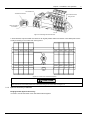
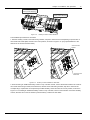
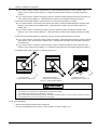
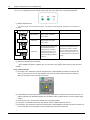
AUTO/MANUAL/LOCK
Switch
Indication
Position
Mark
AU
TO
MA NUA L
LO
CK
Figure 2-18 Switching AUTO/MANUAL/LOCK to AUTO
! CAUTION
Make sure AUTO/MANUAL/LOCK switch lines up with the correct indication position mark
3. Once AUTO/MANUAL/LOCK switch is in the 'AUTO' Position, the switch will automatically transfer to the position
that is currently set in the controller. (For a description of how to set the positions in the controller, refer to the Series
230 C1000 Controller User Manual or Series 230 C2000 Controller User Manual).
! WARNING
1.If the handle has not been removed, the AUTO/MANUAL/LOCK switch cannot be switched to the 'AUTO' Position.
2.After the manual operation, the operator must ensure that the AUTO/MANUAL/LOCK switch moves back to the 'AUTO' Position,
and the Auto/Manual/Lock switch lines up with the 'AUTO' Position indicator mark. Otherwise, the transfer switch will not work in
Automatic Mode.
2.2.3 Padlock
In order for the Padlock Pull Tab to function properly, one must ensure that the switch is in Manual Mode AND the
handle is in the Position OFF. To do this, do the following in this order:
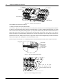
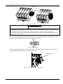
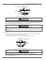
1. Ensure that the AUTO/MANUAL/LOCK switch is in ‘LOCK’ position as shown in Figure 2-19.
AUTO/MANUAL/LOCK
Switch
AU
TO
MA NUA L
LO
CK
Indication
Position
Mark
Figure 2-19 Switching AUTO/MANUAL/LOCK to LOCK
! CAUTION
1. If the transfer switch is not in OFF position,the AUTO/MANUAL/LOCK switch can’t be turned to ‘LOCK’ position.
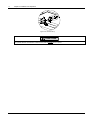
2. If the AUTO/MANUAL/LOCK switch is not in LOCK position, the padlock pull-tab cannot be pulled up.
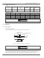
2. Pull the padlock pull-tab out and lift up to expose the lock hole.
lock it. As shown in Figure 2-20.
Then insert the proper padlock into the hole to
ASCO Series 230 B2ADTL Transfer Switch User Manual