1
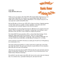
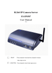
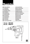
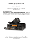
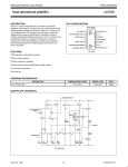
Display and VOX mods pg7
1 of 2
http://www.qsl.net/kf2tz/vox.html#microphone
CHANGE DISPLAY COLOR
Remove top cover of the radio. Locate the 2 white wires running into the display light housing. Remove the
light and remove the green cover on the light. Put the light back into the housing, you can wedge the wires in
between the 3 electrolytic capacitors to hold the light in place. Reassemble the radio and now your radio will
have a light brown display like the big rigs.
ADD VOX
The VOX circuit can be obtained from RASON.org You can wire the TX/RX switch on the front of the radio to
12 volts to turn the VOX on and off.
Microphone wiring
7/28/2007 8:14 AM
Display and VOX mods pg7
2 of 2
http://www.qsl.net/kf2tz/vox.html#microphone
Microphone connector on radio
Pin 1 - Microphone input
* Pin 2 - Push to talk
* Pin 3 - Scan down
* Pin 4 - Scan up
Pin 5 - 8 Volts
Pin 6 - Audio out
Pin 7 - Microphone Ground
Pin 8 - Ground
* NOTE - Connect these pins to ground for function to work
BACK
[email protected]
7/28/2007 8:14 AM
Radio Shack HTX-100 Microphone Amplifier analysis and
improvement
Equipment: Radio Shack HTX-100 10 Meter SSB/CW Transceiver
Catalog Number: 19-1101
On-air reports of muffled audio coupled with off-air confirmation of same led to a technical investigation of the
transmit audio response characteristics of this radio. A cursory review of a few of the 'hacks' on the web (like a
cap across the Mic Att stage) on how to 'cure' or mitigate this muffled audio response spurred me on to write
this web page in order to point out EXACTLY what is taking place inside the HTX-100 to cause 'muffled'
transmit audio AND what a proper 'cure' involves.
It also appeared, during testing, that the microphone was extremely sensitive; verily, this was born out during
testing and the "A"-half of opamp IC3 was found to be operating very near open-loop gain!
Block Diagram
Below is a block diagram with the circuitry under scrutiny shown in red. In particular, the Microphone
Attenuator Q24 (driven by ALC Control Q25) and the Mic Amplifier using one half of IC3 are the subjects of
this webpage. Part of the "ALC" (Automatic Level Control) circuitry (shown in blue) as well as other circuitry
are shown as they 'surround' and interface with circuity around, in, near, or share an opamp in IC3 with the Mic
amp et al.
The Mic Amplifier, using the "A" half Opamp in IC3 delivers an amplified audio signal to the "Gilbert cell"
active component Balanced Mixer, IC2. (Barrie Gilbert on the invention of "The Gilbert Cell".) The output of
IC2 is routed through FT2/FL205; THIS is the filter that makes this radio.
FT2/FL205 is the *sharp* filter that defines the receive characteristis of the HTX100 as well as the ultimate
transmit bandwidth (assuming subsequent RF stages are operated linearly and not into 'clipping'). Shortcomings
in the selected component values of the Microphone Amplifier IC3, however, serve to severely limit the highs
above 1500 Hz (as will be shown further below).
Electronic Schematic Diagram
The following schematic fragment was excerpted from a scanned copy of the HTX-100 Service Manual found
on the web here.
In the following schematic fragment, the following color conventions were chosen to highlight key functions in
the transmit microphone and ALC audio circuitry:
- Red, Audio/Mic circuit input
- Blue, Opamp Output and feedback network
- Green, ALC circuit
Note that the majority of the resistors appearing in that badly drawn and confusing schematic are for bias; that
is, they merely set the DC operating point of the two opamps that are resident in the NJM4558S 9 pin in-line
package. Note also that only one of the two opamps inside the NJM4558S package device is used as an audio
amplifier, the other opamp is used as a simple comparator/level-shifter in the transmit keying circuit.
NJM4558/RC4558 Opamp
Below is the pinout of the NJM4558 IC. Note that this device is a member of the 4558 family of opamps from
such manufacturers as Raytheon and Fairchild as an "RC4558" which is described as a "Dual High-Gain
Operational Amplifier".
The RC4558 integrated circuit is a dual high-gain operational amplifier internally compensated and constructed on a single silicon IC
using an advanced epitaxial process. Combining the features of the 741 with the close parameter matching and tracking of a dual
device on a monolithic chip results in unique performance characteristics. Excellent channel separation allows the use of this dual
device in dense single 741 operational amplifier applications.
Note that the NJM4558 in the "S" package has *two* Vcc pins; pin 1 and pin 9. In the annotated HTX-100
schematic fragment above, R104 (along with R105) provides 'bias'/sets that opamp's DC voltage operating point
(via pin 4) by applying a DC voltage to the non-inverting input of the "A" half of opamp IC3, and furthermore,
this connection is shown to be *through* IC3 to the +8V supply!
NJM4558/RC4558 Opamp - Open loop frequency response
Compare the open loop gain in the chart at around 2 to 3 KHz (around 60 dB) to the gain of an NJM4558 in the
actual Microphone Amplifier circuit as measured further below. It appears the 4558 in this app was running
very near open loop, save for the negative feedback contributed by the 560 pF capacitor.
Microphone Amplifier - AC Circuit analysis
The following schematic was entered to determine the AC characteristics of the HTX-100's
microphone/transmit audio amplifier frequency response.
The following schematic was entered to determine the AC characteristics of the proposed improvements to the
HTX-100's microphone/transmit audio amplifier; note that two resistor values and one capacitor value were
changed per a chart to be found further down below.
Analysis of existing circuit
- Measured Gain (at peak): 56 dB (Av = 630)
- Measured frequency response:
-6 dB
Peak
-6 dB
-10 dB
165
530
1550
2500
Hz
Hz
Hz
Hz
- Modeled frequency response
Circuit value changes to improve high frequency response and modeling of new circuit values as shown below:
Reference
Designator
---------R96
Old
Value
----470K
New
Value
---180K
R98
100
330
C75
560pF
82pF
- Measured Gain (at peak): 45.3 dB
- Measured frequency response:
-6 dB
-3 dB
Peak
-6 dB
-10 dB
140 Hz
250 Hz
1250 Hz
10 KHz
N/A
- Modeled frequency response:
(Av = 184)
On-air testing
In-circuit test of new values; in situ voice quality observation by other operators.
- Indications are that the effort expended resulted in improvements, good reports are now had.
Parts location - changing the components
The area in blue below contains the Microphone Amplifier and Mic Attenuator/ALC circuit components. The
area in blue is shown in more detail in an excerpt further below.
The components outlined in red are the components changed out to improve microphone amplifier frequency
response. To gain access to the rear of the HTX100 Main Board and change these components the PLL
Assembly, located under the Main Board, will have to be temporarily removed; this is an easy task involving
four screws and three connectors: two multi-wire connectors and one coax connection.
After the PLL Assembly is removed the rear of the Main Board is easily accessed to allow desoldering and
removal of the orginal components and installation of the new components.
Link summary:
•
•
•
•
•
Open-loop gain - practically, the gain is so high that the output will be driven to Vcc or Vee for any
appreciable difference between the inverting (-) and non-inverting (+) inputs.
Negative feedback or closed loop gain - feedback is used to 'stabilize' or set the gain to a useful, fixed
value that is relatively independent of the opamp's open-loop (and device fabrication and process yield
dependent) gain figure.
The "Gilbert cell" mixer.
Barrie Gilbert on the invention of "The Gilbert Cell"
HTX-100 Filter comparison with an HR2510 radio.
Over the years, I have talked to several people who have owned both the HR2510 and the HTX100. The comment inevitably comes up that the HTX100 has a 'better
receiver' that the HR2510. But how can this be? Everyone knows that the 2510 and the HTX have virtually identical RF sections.
When I finally managed to acquire an HTX100 last year, I decided to investigate to try and prove or disprove this notion once and for all. Examination of the
schematics for both radios showed that the RF sections were indeed almost identical. I reasoned that the 2510, being an 'allmode' radio with AM included, may use the
common CB radio design practice of having a wider 'compromise' IF crystal filter to improve the RX audio response on AM. The center frequency of both filters is
10.695 MHz, so assuming that the carrier oscillator signal is placed on the slope of the filter, a check of the carrier oscillator alignment frequency for USB should tell
us the approximate bandwidth of the filter. Sure enough, the USB carrier oscillator frequency is different in the two radios! Shown below is a chart of the carrier
oscillator frequencies for both rigs, with a LSB value extrapolated for the HTX100.
As can be seen from the graph, the HTX filter is indeed significantly narrower than the 2510 filter. (Visit this site to view graph.)
•
•
•
HTX-100 Service Manual available here.
4558 opamp history discussed about half-way down in this thread.
What exactly is an Op-Amp?
o HTML web page format
o pdf document format
Intro:
•
•
•
•
The term 'op-amp' was originally used to describe a chain of high performance dc amplifiers that was used as a basis for the analog type computers of long ago. The
very high gain op-amp IC's our days uses external feedback networks to control responses. The op-amp without any external devices is called 'open-loop' mode,
refering actually to the so-called 'ideal' operational amplifier with infinite open-loop gain, input resistance, bandwidth and a zero output resistance.
However, in practice no op-amp can meet these ideal characteristics. And as you will see, a little later on, there is no such thing as an ideal op-amp. Since the
LM741/NE741/µA741 Op-Amps are the most popular one, this tutorial is direct associated with this particular type. Nowadays the 741 is a frequency compensated
device.
Let's go back in time a bit and see how this device was developed.
The term "operational amplifier" goes all the way back to about 1943 where this name was mentioned in a paper written by John R. Ragazzinni with the title "Analysis
of Problems in Dynamics" and also covered the work of technical aid George A. Philbrick. The paper, which was defined to the work of the U.S. National Defense
Research Council, was published by the IRE in May 1947 and is considered a classic in electronics.
•
The very first series of modular solid-state op-amps were introduced by Burr-Brown Research
Corporation and G.A. Philbrick Researches Inc. in 1962. The op-amp has been a workhorse of linear
systems ever since.
Frequency mod pg3
1 of 2
http://www.qsl.net/kf2tz/freqmod.html
FREQUENCY MODIFICATION
Remove bottom and top covers. Remove the PLL board and tray that is held in by 2 screws on each side of
the radio. After you remove the board you will see a 4 sided surface mount chip IC 1208 that has 64 pins.
Look to the right of the chip and locate the 4th and 5th pins from the top right of the chip, pins 28 and 29.
Notice they are soldered together and run to a trace to a surface mount resistor.Carefully cut the trace next to
the 2 pins. Now locate 2 rows of pins to the top of the chip. The bottom row last pin on the right has 5 volts
DC on it. Solder a 10K resistor to that pin and to the pins 28 and 29. Now reassemble the radio and your
done. The radio will now tune 26 MHZ thru 30 MHZ.
7/28/2007 8:11 AM
Frequency mod pg3
2 of 2
http://www.qsl.net/kf2tz/freqmod.html
BACK
7/28/2007 8:11 AM
LSBmod pg5
1 of 1
http://www.qsl.net/kf2tz/lsbmod.html
LOWER SIDEBAND MOD
THIS MOD WILL GIVE YOU LSB AND CW - Remove top and bottom covers. Locate L12 that is an
adjustable metal can inductor located rite behind PC board PC-132AA. To the LEFT of L12 is a 12 picofarad
disc capacitor. Change this to a 47 picofarad capacitor.Readjust L12 to a known source on LSB. Reassemble
the radio and your done.
NOTE: The capacitor I have shown on my diagram is not the one you need to change.
Change the capacitor to the left of L12. I will update the picture soon.
BACK
7/28/2007 8:12 AM
Microphonemod pg4
1 of 1
http://www.qsl.net/kf2tz/micmod.html
MICROPHONE
ENHANCEMENT
Remove top cover of radio. Locate IC3 near the front right of the radio. To the right of the chip and in front of
the chip is a disc capacitor marked 561J, this is a 560 picofarad cap. Remove this capacitor. Now reassemble
the radio. Now your mic will have an added punch that will work great for dx-ing and better under all
conditions.
BACK
7/28/2007 8:12 AM
htx-100 MIC WIRING
1 of 2
http://www.qsl.net/kf2tz/micr.html
Microphone wiring
Microphone connector on radio
Pin 1 - Microphone input
* Pin 2 - Push to talk
* Pin 3 - Scan down
* Pin 4 - Scan up
Pin 5 - 8 Volts
Pin 6 - Audio out
Pin 7 - Microphone Ground
Pin 8 - Ground
* NOTE - Connect these pins to ground for function to work
7/28/2007 8:15 AM
htx-100 MIC WIRING
2 of 2
http://www.qsl.net/kf2tz/micr.html
BACK
[email protected]
7/28/2007 8:15 AM
RITmod pg6
1 of 2
http://www.qsl.net/kf2tz/ritmod.html
OPEN THE RIT
THIS MOD WILL ALLOW THE RIT TO WORK ON TRANSMIT AS WELL AS RECEIVE AT THE
SAME TIME.Remove top cover of the radio. Locate 2 white wires comeing from the display light houseing
going down to the circuit board. Locate the solder pad marked +8 Volts. Now look to the right and you will
see a white plastic wire plug in socket. Next to the socket you will find a 1 inch trace with solder points on
each end that runs front to back direction of the radio. Hook up a DC voltmeter to this trace and write down
the reading. Now turn the radio off and cut the trace in half. Obtain a 10K potentiometer and solder one leg to
the solder pad marked +8 volts. Solder the center leg of the pot to the part of the trace closest to the front of
the radio. Turn the radio on, hook up your voltmeter, positive lead on the leg soldered to the cut trace and
negative to ground. Adjust the pot for the same volt reading you wrote down earlier. This puts the radio back
on frequency. Reassemble the radio and your RIT will now tune 1 1/2 KHZ to each side and track the
frequency on transmit.
7/28/2007 8:13 AM
RITmod pg6
2 of 2
http://www.qsl.net/kf2tz/ritmod.html
BACK
7/28/2007 8:13 AM