1
User’s
Manual
3207
Insulation Polytester
Model: 320731, 320732
IM 3207-E
4th Edition: Sep. 2007
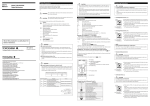
■ Be sure to follow the instructions below to avoid electrical shock or other
dangers that may result in injury of personnel or damage to the instrument.
SAFETY PRECAUTIONS
■ The following safety symbols are used on the instrument and in this
manual.
Danger! Handle with Care.
This symbol indicates that the operator must refer to an
explanation in the User’s Manual in order to avoid risk of
injury or death of personnel or damage to the instrument.
CAUTION
● Measurement
• Do not apply a voltage over the allowable limits between the terminals.
• Do not apply a voltage to the measurement terminal during the measurement
of resistance.
■ Be sure to exercise special care in the following to avoid electrical or
other dangers that may result in injury or the loss of life of personnel.
● Power supply to measured object
• Metals and wring connected to the electric equipment may have a voltage
being applied.
Confirm that no voltage are being applied prior to connecting the measurement terminal.
The same precaution applies to the grounding system.
WARNING
● During measurement of ground resistance
● Batteries
• A high voltage is generated on the measurement leads during the measurement of ground resistance.
• Do not touch the ground spikes or the measurement terminal.
• Do not use different types of batteries together, nor new and old batteries
together. In the case that the instrument is not used for a long period, store
the instrument with the batteries removed.
The batteries may otherwise leak acid which will damage the instrument.
● Measurement lead
• Use the lead supplied by Yokogawa for the instrument concerned.
• Do not use a deteriorated or damaged lead.
• Do not attach/detach the lead to/from the instrument prior to releasing it from
the measured object.
■ Notice Regarding This User’s Manual
● Protection
1. The information covered in this user’s manual is subject to change without prior notice.
2. No part of this document may be reprinted or reproduced without authorization.
3. Every effort has been made to ensure accuracy in the preparation of this
manual.
Should any errors or omissions come to your attention however, please
inform Yokogawa accordingly.
4. Yokogawa is by no means liable for any damage resulting from the user’s
mishandling of the product.
• If the case cracks from being dropped or struck, it may fail to be properly
insulated. Do not use it until it can be repaired.
● Replacement of batteries
• Prior to detaching the cover for replacing the batteries, release the measurement lead from the measured object and do not touch the measurement switch.
A high voltage may otherwise be generated.
● Operating Environment
• Do not operate the instrument in an atmosphere where any flammable or
explosive gas is present.
• Do not use the instrument if there is condensation on it.
● Disassembly
• Do not attempt to disassemble the instrument.
IM 3207-E
– i –
Table of Contents
Page
1. GENERAL .............................................................. 1
2. FEATURE ............................................................... 1
3. NAMES OF PARTS ................................................ 2
4. FUNCTION ............................................................. 3
5. OPERATION ........................................................... 3
6. BATTERY REPLACEMENT ................................... 6
7. CAUTION ............................................................... 7
8. OPTIONAL ACCESSORIES .................................. 7
9. SPECIFICATIONS .................................................. 8
IM 3207-E
– ii –
1. GENERAL
2. FEATURE
■ Compact, lightweight, tough, and easy to operate.
■ Five measurements in one instrument
• Insulation resistance
(Insulation resistance tester)
• Earth resistance
(Earth resistance tester)
• Earth voltage
• AC voltage
(AC voltmeter)
• AC current
(AC ammeter)
The Model 3207, which is indispensable for the inspection
of private electric facilities, electric appliances, and distribution lines, is a measurement instrument equipped with five
functions for measuring insulation resistance, earth resistance,
earthing voltage, AC voltage, and AC current, and is frequently
used for maintenance.
This instrument is composed of a power source, circuit, indicator, and cover. The circuit modules are mounted on the
single printed circuit board. Taut-band meters and impact-resistant plastic are used for the indicator and the cover, respectively, for excellent resistance to vibration and shock. The
Model 3207 has been designed with full consideration of the
functions required for a handy, portable maintenance instrument.
■ Two ratings of insulation resistance:
500V/100MΩ: Model 320731
250V/ 50MΩ: Model 320732
– 1 –
IM 3207-E
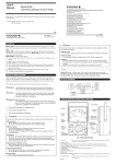
3. NAMES OF PARTS
4
3
2
5
6
1
7
8
1. Range dial
Selects the measuring function and set range.
2. Terminal guide
Indicates where to connect the measuring lead.
3. Measuring terminals
Terminals for connecting the measuring lead.
4. Connector for probe switch
Connecter to use the probe with an insulation resistance
measuring switch (sold separately).
5. Carrying bag (Hard)
Storage case for the main body. A knapsack is available for
storing accessories.
6. Indicator
Indicates the measured value.
7. Zero adjuster
Screw to adjust the indicator’s mechanical zero position.
Usually, there is no need for adjustment.
8. Push button switch (can be locked)
Press this switch to start measurement.
Hold down this switch and turn it clockwise to lock it.
IM 3207-E
– 2 –
5. OPERATION
4. FUNCTION
5.1 Battery Check (B)
Rating
Function
Symbol
Insulation
resistance
MΩ
(Black)
<1> 500V/100 MΩ
<2> 250V/50 MΩ
–
(1) When insulation resistance and earth resistance are
measured, battery check should be made in advance.
Set the range dial to “B” and push the switch. If the
Earth
resistance
EΩ
(Blue)
0 to 15/150/1500Ω
–
indicating pointer stays within the blue belt, the builtin batteries are of use.
AC voltage
V (Red)
70 to 130 V
/140 to 260 V
/280 to 520 V
AC current
A (Black)
0 to 15/30/75/150/
300 A (with CT)
(2) If the pointer dose not reach the belt, the batteries
must be replaced with new ones.
(For details, see “6. Battery Replacement”.)
Compatible
with
50 and
60 Hz
5.2 Insulation Resistance Measurement
(MΩ)
(1) Set the range dial to “MΩ” and connect the accessory leads (black and orange) to the respective measuring terminals E (Earth) and L (Line). Then connect the leads between the probes and the object,
and press the switch to read the insulation resistance
<1> Model: 320731
<2> Model: 320732
Other check functions:
directly.
Battery (built-in) Check: B (Blue)
Earth resistance Check: CH (Blue)
Earthing voltage Check: EV (Blue) 0 to 30 V
(2) When using Guard, connect to “G” terminal (Central
terminal).
(3) The probe switch (an accessory, sold separately) can
be used as the line probe which is connected to the
socket on the instrument.
CAUTION
Do not change the range dial during measurement.
Measuring terminals
Terminal guide
– 3 –
E
G
L
IM 3207-E
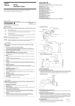
(2) If the pointer does not stay within the CH blue belt,
auxiliary spikes should be more tightly stuck into the
ground. For auxiliary earthing, there are other methods shown in Fig.2 according to the ground conditions. (To use the auxiliary net: sold separately)
5.3 Earth Resistance Measurement (EΩ)
(1) Set the range dial to “CH”, make connections as
shown in Fig.1 with the accessory leads
(green, yellow and red) and the auxiliary spikes (P,
C). Push the switch to assure that the pointer comes
into the CH blue belt. Then turn the dial to “EΩ” and
push the switch again selecting a suitable range according to the earth resistance.
Connect earthing electrodes (E) and auxiliary spikes
(P, C) to the main body using the accessory lead lines
as shown in Fig. 1. Leave space of 5 to 10 m between E and P, and between P and C respectively. E,
P and C should be approximately in a line.
R
Water
Soft ground
Hard ground
Auxiliary nets
Fig.2
R
E
P
C
Rx Yellow
Green
Water
Red
R=5 to 10m
Fig.1
IM 3207-E
– 4 –
(3) Simplified two-electrode method
When measuring earth resistance (D), a simplified
measuring method is available where there is something to serve as an almost perfect earthing like a
water pipe (Plastic pipe must be avoided). (Fig. 3)
The distance between the earth (E) and water pipe
must be 5 to 10 m.
shown in Fig.4 and marking sure that EV is small
enough. A large EV means that the wiring or loads
are poorly insulated, and so the insulation resistance
test must be kept within the MΩ range of this tester.
Leakage current
Transformer
Switch
Wiring
Switch
E
E
Load
E'
EV (Earting Voltage)
5 to 10 m
Fig.4
Rx
5.4 AC voltage Measurement ( V )
Fig.3
Set the dial to a suitable range of “ V”, according to the
voltage to be measured. Connect the accessory leads to
the terminals. (The leads are used for insulation resistance measurement, too.)
“ V” has both 130 V and 520 V ranges. Upon connecting to the central terminal, both ranges are converted to
260 V.
Each range has a suppressed-zero scale whose median is respectively 100 V, 200 V, and 400 V.
(4) Earthing voltage Check (EV)
Poorly insulated wiring or equipment may cause an
earthing voltage (EV) due to the leakage current
through the earthing resistance to be measured. If
this earthing voltage is too high, it may cause an error in measurement. To detect EV, turn the dial to
“EV” and if it is more than approximately 5V (䉱mark
on the scale), it will bring about an error in measuring
the earth resistance. Therefore, the measurement
should be proceeded by disconnecting the switches
Measuring terminals
Terminal guide
260V
– 5 –
520V
130V
IM 3207-E
5.5 AC Current Measurement (A )
6. BATTERY REPLACEMENT
Set the dial to a suitable range of “ A ” and connect the
chips of Clip-on CT (Part No. B9103BA) with the terminal
A (CT).
Clip on a current line (cable) at the center of the core
as shown in Fig.5.(Errors by displacement from the center are less than ±1%)
When the pointer stays out of the blue belt (B) during “5.1
Battery Check”, the batteries should be replaced with all new
ones. [R6P (SUM-3) 8 pcs.] To replace batteries, take off the
covering case by loosening two screws and put new batteries
in the place of consumed ones according to the polarities described on the battery holder. Do not touch the parts and wires
inside when removing the covering case.
Position for cable
Clip-on CT
Fig.5
IM 3207-E
– 6 –
7. CAUTION
8. OPTIONAL ACCESSORIES
(1) Lock of the pushbutton switch
When using ranges B, MΩ, CH and EΩ, it is necessary to
push the switch each time. And in case of long-time measurement the switch can be locked by merely turning it
clockwise after pushing.
After measurement, unlock the switch to turn off.
(2) If it is wet around the measuring terminal (especially during insulation resistance measurement), dry off the area
before use.
(3) Range check
• Always check the setting position of the range dial and
the connection of terminals before starting measurement.
• Do not change the setting position of the range dial during measurement.
The following accessories are sold separately.
䊊 Part No. B9606FA : Probe switch for Insulation Resistance Measurement (Cable length: approx. 1m)
Old Part No.: B9646CE
䊊 Part No. B9646CG :Auxiliary nets for Earth Resistance
Measurement --- 2 pcs. 30 ⫻ 30 cm
– 7 –
IM 3207-E
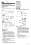
9. SPECIFICATIONS
<1> Model 320731
Measurement
Rating
Range
<2> Model 320732
Insulation Resistance
<1>500V/100 MΩ
<2>250V/50 MΩ
Earth Resistance
Earth Voltage
AC Voltage
AC Current
1500Ω
0-15/150/1500Ω
0-30V
70-130V/
140-260V/
280-520V
0-15/30/75/
150/300A
(Model is to be specified)
Method of
measurement
Constant voltage converter
Constant current inverter
Rectification
Suppression (Rectification)
Clip current transformer
(Rectification)
Accuracy
±5% of reading within
the 1st effective measuring range
±10% of reading within
the 2nd effective measuring range
0.7% or less of scale length at zero and infinity
±3% of full scale
±3% of full scale
±1.5% of full scale
±2.5% of full scale
Uniform (Red)
Uniform (Black)
Scale
Three-digit logarithmic (Black)
Uniform (Blue)
Uniform (Blue)
Remarks
Terminal voltage indicated by a central
scale is more than 90% of the rated voltage.
Measuring frequency:
1.8kHz
Allowable earthing voltage:
5V
Dimensions
Approx. 140 ⫻ 210 ⫻ 142 mm (Including bag)
Weight
Approx. 2.3 kg (Including bag)
Battery
R6P (SUM-3) 8 pcs.
Accessories
Batteries
Leads for insulation resistance and AC V measurement (B9606CR)
Leads for earth resistance measurement (B9605KN)
Auxiliary spikes for earth resistance measurement (B9606CD)
Clip-on current transformer (B9103BA)
: R6P (SUM-3) 8 pcs. built-in
: 1 set (black and orange: 1.5m)
: 1 set (green, yellow and
red: 5, 10, 20m)
: 2 pcs. (32cm)
: lead length 2m
For both 50 and 60Hz
Accessory carrying bag (B9606CH) : Fabric knapsack
Carrying bag (B9646CK)
: black shoulder
bag (hard)
Nameplate
: English names is
to be specified.
User’s manual
: 1 copy
Effective measuring range : The range from a resistance value one-thousandth (1/1000) the maximum effective reading to the resistance value that is
nearest to half (1/2) the maximum effective reading and equal to the maximum effective reading multiplied by 1, 2 or 5 or by
any of these values multiplied by ten (10) raised to a whole-number power, shall be referred to as a first effective measuring
range.
In addition, the range from the upper limit of the first effective measuring range to the maximum effective reading shall be
referred to as second effective measuring ranges.
AC Voltage
: (Caution) A suppressed-zero instrument swings in the opposite direction when measuring a voltage which is below the rating.
IM 3207-E
– 8 –
MEMO
– 9 –
IM 3207-E
MEMO
IM 3207-E
– 10 –
Yokogawa Meters & Instruments Corporation
International Sales Dept.
Tachihi Bld. No.2, 6-1-3, Sakaecho, Tachikawa-shi,Tokyo 190-8586 Japan
Phone: 81-42-534-1413, Facsimile: 81-42-534-1426
YOKOGAWA CORPORATION OF AMERICA (U.S.A.)
Phone: 1-770-253-7000 Facsimile: 1-770-251-2088
YOKOGAWA EUROPE B. V. (THE NETHERLANDS)
Phone: 31-334-64-1611 Facsimile: 31-334-64-1610
YOKOGAWA ENGINEERING ASIA PTE. LTD. (SINGAPORE)
Phone: 65-6241-9933 Facsimile: 65-6241-2606
YOKOGAWA AMERICA DO SUL S. A. (BRAZIL)
Phone: 55-11-5681-2400 Facsimile: 55-11-5681-1274
YOKOGAWA MEASURING INSTRUMENTS KOREA CORPORATION (KOREA)
Phone: 82-2-551-0660 to -0664 Facsimile: 82-2-551-0665
YOKOGAWA AUSTRALIA PTY. LTD. (AUSTRALIA)
Phone: 61-2-9805-0699 Facsimile: 61-2-9888-1844
YOKOGAWA INDIA LTD. (INDIA)
Phone: 91-80-4158-6000 Facsimile: 91-80-2852-1441
YOKOGAWA SHANGHAI TRADING CO., LTD. (CHINA)
Phone: 86-21-6880-8107 Facsimile: 86-21-6880-4987
YOKOGAWA MIDDLE EAST E. C. (BAHRAIN)
Phone: 973-358100 Facsimile: 973-336100
LTD. YOKOGAWA ELECTRIC (RUSSIAN FEDERATION)
Phone: 7-095-737-7868 Facsimile: 7-095-737-7869
IM3E-2006.2