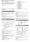
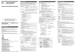
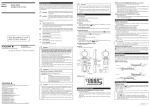
1
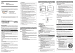
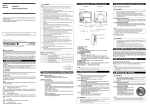
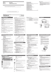
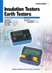
User’s
Manual
3213A
Insulation Tester
Yokogawa Meters & Instruments Corporation
Please read through this instruction manual before starting operation in order to ensure
correct and effective use of Model 3213A Insulation Tester.
1st Edition : June 1994 (YG)
All Rights Reserved, Copyright © 1994, Yokogawa M&C Corporation
International Sales Dept.
Tachihi Bld. No.2, 6-1-3, Sakaecho, Tachikawa-shi,Tokyo 190-8586 Japan
Phone: 81-42-534-1413, Facsimile: 81-42-534-1426
YOKOGAWA CORPORATION OF AMERICA (U.S.A.)
Phone: 1-770-253-7000 Facsimile: 1-770-251-2088
YOKOGAWA EUROPE B. V. (THE NETHERLANDS)
Phone: 31-334-64-1611 Facsimile: 31-334-64-1610
YOKOGAWA ENGINEERING ASIA PTE. LTD. (SINGAPORE)
Phone: 65-6241-9933 Facsimile: 65-6241-2606
YOKOGAWA AMERICA DO SUL S. A. (BRAZIL)
Phone: 55-11-5681-2400 Facsimile: 55-11-5681-1274
YOKOGAWA MEASURING INSTRUMENTS KOREA CORPORATION (KOREA)
Phone: 82-2-551-0660 to -0664 Facsimile: 82-2-551-0665
YOKOGAWA AUSTRALIA PTY. LTD. (AUSTRALIA)
Phone: 61-2-9805-0699 Facsimile: 61-2-9888-1844
YOKOGAWA INDIA LTD. (INDIA)
Phone: 91-80-4158-6000 Facsimile: 91-80-2852-1441
YOKOGAWA SHANGHAI TRADING CO., LTD. (CHINA)
Phone: 86-21-6880-8107 Facsimile: 86-21-6880-4987
YOKOGAWA MIDDLE EAST E. C. (BAHRAIN)
Phone: 973-358100 Facsimile: 973-336100
LTD. YOKOGAWA ELECTRIC (RUSSIAN FEDERATION)
Phone: 7-095-737-7868 Facsimile: 7-095-737-7869
IM3E-2006.2
A3
IM 321341-01E
4th Edition:Jan. 2007
Safety Precautions
1. Component Names
(2) Earth Terminal Release Button
■ For safe use of this tester, the following safety symbols are used in the user's manual:
Danger! Handle with Care.
This symbol indicates that the operator must refer to an explanation in the user’s manual in
order to avoid risk of injury or death of personnel or damage to the tester.
(1) Measuring Lead Unit
(5) Battery Check Mark
(BAT Mark)
(4) Switch (with lock)
High-voltage Terminal
This symbol indicates a dangerous voltage level (terminals with voltages exceeding 1000
volts must be so marked). Never touch the terminals.
(3) Line Terminal Release Button
(6) Battery Check Terminal
WARNING Indicates a hazard that may result in the loss of life or serious injury of the user unless the
described instruction is abided by.
CAUTION
Indicates a hazard that may result in an injury to the user and/or physical damage to the
product or other equipment unless the described instruction is abided by.
(7) Case
(8) Strap
(9) Jack for the Optional Probe with a Switch
(11) Earth Terminal
WARNING
■ To avoid injury, death of personnel, carefully observe and follow the warnings
listed below:
1. During the measurement of insulation resistance
• A high voltage is generated in the probe during the measurement of insulation resistance.
Do not touch the measured object, the EARTH or LINE terminals or the GUARD terminal.
2. During the measurement of AC voltage
• There is AC voltage at the GUARD terminal during the measurement of AC voltage. Do not
touch the GUARD terminal.
3. Immediately after the measurement of insulation resistance
• The probes or measured object may remain highly charged. Do not touch them immediately
after measurement.
4. Probe
• Use the probe supplied by Yokogawa Meters & Instruments Corporation for the instrument
concerned.
• Do not use a deteriorated or damaged probe.
• Do not attach/detach the probe to/from the instrument prior to releasing it from the measured
object.
5. Protection
• If there are any cracks or other damage in the case because of being dropped or struck, the
instrument may not be safely insulated. Do not use the instrument before any remedial measures
are taken.
6. Object to be measured
• When insulation resistance is measured, turn off the power to the measured object.
• When the instrument is used in a location where an electric current is flowing, never touch the
power line.
Use rubber gloves as a safety precaution.
7. Replacement of batteries
• Prior to detaching the cover for replacing the batteries, release the probe from the measured
object and turn off the switch.
• Do not touch the measurement switch during replacement. Otherwise, a high voltage may be
produced.
8. Operating Environment
• Do not operate the instrument in a flammable or explosive gas atmosphere.
• Do not operate the instrument if there is condensation on it.
9. Disassembly
• Do not attempt to disassemble the instrument.
Earth Lead Clip
Line Probe
(12) Guard Terminal
(10) Line Terminal
(13) Handling Guide
(15) Screw to Fasten Bottom Cover
(14) Bottom Cover
Measuring Lead Unit
Outline of Measurement Principle
Meter display
Measurement
switch
High voltage
generator
circuit
LINE
Logarithm
conversion circuit
GUARD
EARTH
Eight AA-size
batteries
2. Measuring Operations
● Connecting the Measuring Lead Unit
Connect the measuring lead unit (1) to the tester by inserting its plugs into the line terminal (10) and
earth terminal (11). Be sure to insert the plug of the line probe to the line terminal, and the plug of the
earth lead clip to the earth terminal. These plugs are locked once they are securely inserted.
Measurement wiring
Power supply side
(primary)
Set the switch to OFF.
ON
Earth probe
OFF
CAUTION
■ To avoid injury of personnel or damage to the instrument, carefully observe and
follow the cautions listed below.
1. Measurement of AC voltage
• Do not apply a voltage over the allowable limits between the terminals.
2. GUARD terminal
• The GUARD terminal is an auxiliary measurement terminal to eliminate a leakage current. Do
not apply a voltage to the terminal.
3. Power supply to the measured object
• Metals and wiring connected to the electric equipment may have a voltage being applied.
Confirm that no voltage is being applied prior to connecting the measurement terminal. The
same precaution applies to the grounding system.
4. Batteries
• Do not use different types of batteries together or new and old batteries together. If the
instrument is not used for a long period, store the instrument with the batteries removed.
Otherwise, any leakage from the batteries may damage the instrument.
Line probe
Load side
(secondary)
Grounding
electrode
● Disconnecting the Measuring Lead Unit
Disconnect the measuring lead unit while pressing the earth terminal and line terminal release buttons
(2) and (3) simultaneously.
● Measurement of Insulation Resistance
If the object to be measured is earthed, connect the earth lead clip to the earthing point of the object.
Apply the line probe of the measuring lead unit (1) to the object to be measured, then press the switch
(4). The tester needle indicates the obtained insulation resistance value. When applying the line probe,
do not allow its lead wire to come into contact with the earth, floor, or other object. If this happens,
insulation resistance cannot be measured correctly. The earth lead clip may be
either connected if the object to be measured is not earthed.
● Locking the Switch
Pull up the switch (4) to keep it in the ‘on’ position. This function is useful if
measurement is to continue for a long time. If the locked state is prolonged,
however, the battery will quickly become depleted.
● Using the Optional Probe with a Switch
Insert the probe plugs to the line terminal (10), earth terminal (11), and jack (9). To start measurement,
press the probe switch instead of the switch (4) on the main unit.
● Measurement of Volume Resistance
Volume resistance alone can be measured without any effect of surface leakage resistance. When
testing a cable, for example, wrap a bare wire around the
insulating material, and connect an optional lead for guard
Core Wire
terminal between the bare wire and the guard terminal (12)
LINE
Bare Wire
as shown in the figure on the right. This prevents leakage
Indicator
Insulating
current on the insulating material from flowing into the
Power
Material
GUARD
Source
Metal-Sheath
tester; thus only volume resistance can be measured
EARTH
Instrument Proper
correctly. When measuring volume resistance, the optional
lead for guard terminal (model: 321803) must be used for
connection to the guard terminal.
WARNING
Beware of electric shock. There is voltage between the earth and line terminals and between the
earth and guard terminals.
3. Zero Checking
Connect the line terminal (10) and earth terminal (11) together using the measuring lead unit (1), and press
the switch (4). If the tester needle indicates a reading not exceeding the zero scale indication, the tester is
considered normal. If it does not, check the batteries following the instructions given in Item 4, “Checking
the Batteries.” If the batteries have run down, replace them as described in Item 5, “Replacing Batteries,”
and then perform zero checking again. If the tester needle does not indicate the proper point even though
the batteries are still available, the tester requires adjustment. Please contact your nearest Yokogawa.
4. Checking the Batteries
1. Without pressing the switch, apply the line probe to
both poles of the battery check terminal (6)
simultaneously as shown in the figure on the right.
2. If the tester needle indicates any reading below the
battery check mark (BAT) (5) on the scale plate, the
batteries can still be used.
3. Readings above the battery check mark mean that the
batteries have run down. Replace them according to
the instructions given in Item 5, “Replacing Batteries.”
5. Replacing Batteries
l. Loosen the screw (15) on the bottom cover using a coin or similar, and then remove the bottom cover
(14).
2. Replace all 8 batteries at the same time. Batteries must be placed oriented according to the indication
written on the holder.
CAUTION
Response time:
Within three seconds to reach the tolerance range after resistances equivalent to
the central and zero scale readings are suddenly applied to the tester.
Instantaneous maximum voltage: No more than 1.5-fold the rated measuring voltage.
Effect of temperature: When the ambient temperature is raised to 40°C and lowered to 0°C both from
23°C, variations shall be within 5% of the scale length at the central scale
mark, and within 0.7% at the infinity scale and zero scale marks.
Effect of humidity:
The specified tolerances shall be met after the tester has been left under the
condition of 90% relative humidity for one hour.
Effect of external magnetic field: A change shall be within 10%when the maximum, center, and
minimum values of the first effective measuring range are indicated and an
external field of 400 A/m DC is applied in the most affected direction.
Effect of inclination:
Within 2% of the scale length when tested at the infinity scale mark by
inclining the tester 90° forward and backward then to the right and the left
from the horizontal.
Effect of external voltage: When an AC voltage 1.2-fold the rated measuring voltage at 50 Hz or 60 Hz
is applied between the measuring terminals for 10 seconds with the switch (4)
being turned on and then off, there is no abnormality.
Battery voltage:
Within the effective battery range (below the battery check mark on the scale
plate).
Possible number of measurements: When the measuring time is five seconds each with approximately
25 seconds between measurements, using manganese batteries and the
minimum resistance that can be measured while the rated measuring voltage is
connected.
Model
Range
Number of measurements
321341
100 V/20 M⍀
Approx. 5,700
321342
250 V/50 M⍀
Approx. 5,300
321343
500 V/100 M⍀
Approx. 3,000
321344
500 V/1000 M⍀
Approx. 3,000
321345
1000 V/2000 M⍀
Approx. 1,000
Withstand voltage:
3700 V AC for one minute between the electric circuits and the outer case.
Scale length:
Approximately 84 mm
Protection against water, solid matter, and dust penetration: JIS C0920 compliance, class IP 40:
Foreign substances of 1.0 mm or more in diameter must not enter at all.
Vibration proof:
When a vibration frequency of 25 Hz and a peak-to-peak amplitude of 1 mm is
applied for 20 minutes in each of three directions that are perpendicular to each
other, the specifications for tolerances are met.
Shock proof:
When a half-sine pulse shock of a 1000 m/s2 peak acceleration is applied in
both forward and reverse for 6 ms, three times in each of three directions—
totaling 18 times—specifications for tolerance are met.
Operating temperature/humidity range: 0 to 40⬚C; within 90%RH (no condensation)
Storage temperature/humidity range: - 10 to 60⬚C; within 70% RH (with batteries removed, no
condensation)
External dimensions
: Approx. 177×105×55mm
Weight
: Approximately 700 g (including batteries)
Approximately 1.2 kg (including carrying case, strap, measuring lead unit,
and batteries)
Accessories
A malfunction may occur if a dead battery leaks.
6 AC Voltage Measurement
This tester can also measure AC voltages of commercially-available frequencies. Therefore, use this
function during the insulation resistance test to confirm that there is no voltage applied to the object to be
measured.
1. Insert the measuring lead unit (1) to the tester by inserting its plugs into the line terminal (10) and
earth terminal (11) in the same manner as when measuring insulation resistance.
2. Apply the measuring lead unit to the AC voltage test point, and read the indication on the voltage
measuring scale (AC V). Do not press the switch (4) when measuring AC voltages.
Name
Battery
(1) Measuring lead unit
(2) Carrying case
(3) Strap
• Instruction manual
Model/Part Number
R6P (AA (SUM-3) or equivalent)
B9205VA
B9600HA
B9303XE
IM321341-01E
Description
Contained in the main unit
Equipped with both earth and line leads
With a test lead storage bag
This manual
Optional Accessories
(1)
Name
(4) Probe tip
Model/Part Number
B9600GN
B9600NW
B9600NX
B9600NZ
B9635JK
B9600NV
321802
321803
WARNING
Do not connect a guard-terminal lead to the guard terminal (12). AC voltage is applied to the guard
terminal during AC voltage measurement. This may cause electric shock.
Quantity
8
1
1
1
1
(5) Probe tip storage bag
(6) Probe with a switch
(7) Lead for guard terminal
Description
General-purpose
With a hook
With extension
Pointed
Pickax-shaped
(2)
(3)
(4)
Supplies
8. Specifications
Specifications for this instrument conform to JIS C1302-2002 (Japanese Industrial Standard).
Model
Rating
321341
321342
321343
321344
321345
100 V/20 M⍀
250 V/50 M⍀
500 V/100 M⍀
500 V/ 1000 M⍀
1000 V/2000 M⍀
First Effective
Measuring Range
0.02 to 10 M⍀
0.05 to 20 M⍀
0.1 to 50 M⍀
1 to 500 M⍀
2 to 1000 M⍀
Second Effective
Measuring Range
10 to 20 M⍀
20 to 50 M⍀
50 to 100 M⍀
500 to 1000 M⍀
1000 to 2000 M⍀
Central Scale
Mark
0.5 M⍀
1 M⍀
2 M⍀
20 M⍀
50 M⍀
AC Voltage
Measuring Range
0 to 150 V
0 to 250 V
0 to 300 V
0 to 300 V
0 to 300 V
Low-limit
Measuring Resistance*
0.1 M⍀
0.25 M⍀
0.5 M⍀
0.5 M⍀
1 M⍀
Rated
Current
1 mA
1 mA
1 mA
1 mA**
1 mA**
GN
Name
(1) Measuring lead unit
Part Number
B9205VA
(2) Carrying case
B9600HA
• Test lead storage bag
(3) Strap
B9646CA
B9303XE
Description
Equipped with both
earth and line leads
With a test lead
storage bag
JK
(6)
NW
NX
NZ
(7)
(5)
Measuring Terminal Voltage Characteristics
700
600
500
400
300
321343
321342
200
100
0
0.01
321341
0.1
1
10
100
⬁
Measuring Terminal Voltage (V)
■ Storage Conditions
• Temperature: -10 to 60⬚C
• Humidity: 70% RH or less (with batteries removed, no condensation)
• Keep the instrument away from moisture, direct sunlight, heat, vibration, dust, coastal air, and
corrosive gases.
■ Cleaning
Clean the instrument with a damp cloth using water or alcohol. Use of a volatile solvent such as a
thinner or benzine may cause discoloration.
■ Calibration
Interval between calibrations: One year
Periodic calibration is required to ensure the accuracy of measurement. Please contact your nearest
Yokogawa for calibration.
Measuring Terminal Voltage (V)
7. Maintenance
× 1000
1.4
1.3
1.2
1.1
1
0.9
0.8
0.7
0.6
0.5
0.4
0.3
0.2
0.1
0
321345
321344
0
1
10
100
1000
⬁
Measuring Resistance (M⍀)
Measuring Resistance (M⍀)
External Dimensions
* : The minimum reading that can maintain the rated voltage.
**: 0.55 mA in the first effective measuring range.
Standard Conditions
Ambient temperature
Relative humidity
Position
External magnetic field
Battery voltage
:
:
:
:
:
23⫾5⬚C
45 to 75%RH
Horizontal (within 5⬚ of the horizontal)
None
Within the effective battery range (below the battery check mark on the scale
plate).
Tolerances (under standard conditions)
Measured resistance
: ⫾5% in the first effective measuring range
⫾10% in the second effective measuring range
Infinity scale and zero scale: Within 0.7% of the scale length
AC voltage
: ⫾10% of the maximum reading
Open-circuit voltage
: Within 130% of the rated voltage
Rated measuring current : -0% to +20% of 1 mA in the first effective measuring range
Short-circuit current
: Within 12 mA
Effect of AC component of voltage at measurement terminals: Within 10% of reading when a
capacitor of 5 µF ±10% is connected in parallel with a resistor the value of
which is determined from the rated measuring voltage and current, and which
is itself connected to the measuring terminals.
Unit: mm
■ Notice Regarding This Instruction Manual
1. The contents of this instruction manual are subject to change without prior notice.
2. If any questions arise or errors are found, or if any information is missing from this manual, please
inform Yokogawa Meters & Instruments.
3. Yokogawa Meters & Instruments is by no means liable for damage resulting from the misuse of this
product by the user.
4. This manual is intended to explain the function of this product. Yokogawa Meters & Instruments does
not warrant that the functions will suit a particular purpose of the user.