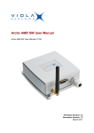
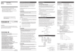
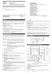
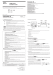
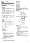
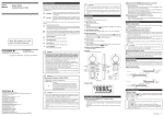
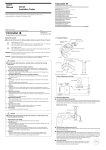
1
User’s
Manual
2755
Portable Wheatstone Bridge
With Murray and Varley Loop Tester
IM 2755-97E
5th Edition: June 2007
Cautionary Notes for Safe Use of the Product
■ Since mishandling the instrument can result in an accident,
such as an electric shock, that may injure the operator or
damage the instrument, be sure to observe the following
instructions.
■ The following symbol is indicated on the instrument to ensure
safe use.
"Handle with care!" This symbol is indicated where
the operator must refer to instructions in the
manual or attached material in order to protect
personnel and the instrument.
■ Since mishandling the instrument can result in an accident
that may lead to injury or death of the operator, such as an
electric shock, be sure to observe the following instructions.
CAUTION
● Batteries
• Do not use a mixture of different types of batteries or a mixture of old
and new batteries. If the instrument will not be used for a prolonged
period, remove the batteries before storage. The battery fluid will leak
more readily during long-term storage, resulting in an instrument
malfunction.
● Plastic Case
• The panel and case of this instrument are made of ABS resin. Special
caution must be taken to protect them from heat and organic solvent
such as lacquer thinner.
WARNING
● Protective Measures
• If a crack appears in the instrument after it has been accidentally
dropped or bumped, the safety-purpose insulation may be damaged.
By all means do not use the instrument, but ask the manufacturer for
repair.
● Connection
• To avoid electric shock, be sure to apply protective grounding to the
grounding terminal.
● Measurement
• Always maintain the instrument within the limits for allowable current,
voltage and power, during operation. If there is more than one limit for
any of these parameters, the lowest limit takes precedence.
● External Power Supply
• Only operate the instrument on a supply voltage no greater than 70 V
DC.
● Operating Environment
• Do not operate the instrument in a flammable or explosive gas
atmosphere.
• Do not operate the instrument if there is any condensation on it.
● Disassembly
• Nobody except members of the manufacturer's service staff is allowed
to disassemble the instrument.
Notice regarding This User's Manual
1. The information covered in this user's manual is subject to change without
prior notice.
2. Every effort has been made to ensure accuracy in the preparation of this
manual. Should any errors or omissions come to your attention however,
please inform Yokogawa Corporation accordingly.
3. Yokogawa Corporation is by no means liable for any damage resulting from
the user's mishandling of the product.
IM 2755-97E
– i –
Precautions for Use
WARNING
CAUTION
● External Power Supply
When external power supply is employed to increase sensitivity, full
caution must be taken to avoid excess current flow, since all wirewound bridge elements used in this instrument can endure up to 1 watt
max. Before higher voltage is applied, take rough balance of bridge with
low voltage. Caution must be taken not to set ⫻ 1000 dial to "0" and not
to short-circuit Rx terminals.
● Operation of Button Switch
• BA and GA button switches should be at OFF position after
measurement.
• During measurement, BA button switch must be pressed prior to GA
button switch. If this order is inverted, the movement of the
galvanometer will be kicked when BA button switch is pushed due to
inverse emf of inductance of the object under test, and the direction
of measuring dial adjustment shall be thereby misled.
● Lead Resistance
In measurement of resistances below 10 ohms, the lead wire
resistance should not be neglected. The lead resistance
compensation must be made by measuring the lead resistance
separately.
IM 2755-97E
– ii –
CONTENTS
Page
1.
GENERAL ................................................... 1
2.
SPECIFICATIONS ....................................... 1
3.
CONSTRUCTION ....................................... 3
3.1
Front Panel .................................................. 3
3.2
External Galvanometer ............................... 4
3.3
External Power Supply ................................ 4
3.4
Cell Replacement ........................................ 5
4.
OPERATION ............................................... 6
4.1
Preparation .................................................. 6
4.2
Resistance Measurement ........................... 6
4.3
To find out approximate value of Rx ............ 7
4.4
Interpolation ................................................ 8
4.5
Murray Loop Test ......................................... 8
4.6
Varley Loop Test .......................................... 9
5. PRINCIPLES OF OPERATION ............................ 10
6. MAINTENANCE ................................................... 11
COMPONENT LOCATION DIAGRAM ...................... 11
PART LIST ................................................................ 12
CIRCUIT DIAGRAM .................................................. 13
IM 2755-97E
– iii –
1. GENERAL
Measuring arm
The 2755 Portable Wheatstone Bridge is quite conve-
1000:
0.06%
100:
0.1%
nient with general resistance measurement and fault point
10:
0.5%
detection of lines by Murray and Varley loop testing meth-
1:
3% (Including residual
ods.
resistance)
Multiply dial (Ratio)
2. SPECIFICATIONS
Measuring Range:
Measuring arm:
0.1, 1, 10:
0.07%
1Ω to 10MΩ (4 digits)
100, 0.01:
0.2%
1Ω10+10Ω10+
1000, 0.001:
0.5%
M10, M100, M1000:
0.1%
100Ω10 + 1000Ω10
Temperature Coefficient of Resistance Elements
(4 dials)
Ratio arm:
0.001, 0.01, 0.1, 1, 10,
less than
210–5/°C (20 to 35°C)
100, 1000 and for Murray loop
Galvanometer
test M10, M100, M1000
Accuracy
Overall
100Ω to 100kΩ:
0.1% of reading
10Ω to 1MΩ:
0.3% of reading
1Ω to 10MΩ:
0.6% of reading
510–5/°C (5 to 35°C)
IM 2755-97E
– 1 –
Sensitivity:
0.9µA/div. (20%)
Internal resistance:
150Ω (20%)
Period:
Within 2.6 seconds
Operating Temperature: 5 to 35°C
Operating Humidity: 85% R.H. or less
(Note)
Power Source: Three 1.5V batteries (built-in) type SUM-1
* For the measurement of more than 100kΩ, it is recom-
Dimentions: Approx. 182226128mm
mended to use external galvanometer, which has high sen-
Weight : Approx. 2kg (4.4lbs)
sitivity.
Accessory
For example, the 2707 Electronic Galvanometer (Portable
User's manual: 1 copy.
type 10µV/div. sensitivity) is suitable for above requirement.
Carrying case (B9350AW): 1pc.
It is possible to measure 0.1% variation of Rx value of 2MΩ
Optional Accessory
(4.5V power supply).
Carrying case: B9350AW (275600)
IM 2755-97E
– 2 –
3. CONSTRUCTION
3.1 Front Panel
POWER SUPPLY
SELECTOR SWITCH
MV-R SELECTOR
SWITCH "G" TERMINAL
EXTERNAL
BATTERY TERMINALS
MEASURING
ARM DIALS
MULTIPLY
DIAL
EXTERNAL
GALVA TERMINALS
ZERO ADJUSTOR
UNKNOWN
RESISTANCE
PUSH BUTTON
SWITCH
Fig 3.1 Panel
IM 2755-97E
– 3 –
3.2 External Galvanometer
When a high sensitive galvanometer is required,
move short circuitting bar and short "INT.GA." terminals.
After that, connect the galvanometer to "EXT. GA."
terminals are shown in Fig. 3.2.
3.3 External Power Supply
When external power supply is necessary, connect the power supply to –B and +B terminals and
Fig 3.2 Connection of External Galvanometer
turn the power supply selector switch to "EXT BA".
Minimum circuit resistance between –B and +B
BATTERY
–
+
terminals is approximate 1010 ohms.
Maximum external power supply voltage is 70V
EXT
BA
–B
+B
DC and maximum current is 60mA DC (Continuous).
1 KΩ (2W type) protective resistance is inserted
between the external power supply and bridges, so
when the 1000 dial is set to 0, the circuit is pro-
Fig 3.3 Connection of External Battery
tected from overcurrent.
IM 2755-97E
– 4 –
3.4 Cell Replacement
Remove the cell cover on the bottom of the case,
by pulling leg of the cover while pushing the clamping plate towards the arrowed direction to the end. To
restore the cell cover, push the clamping plate towards the arrowed direction, insert the hollowed part
of the cover under the clamping plate and press the
cover down.
Fig 3.4 Removal of Cell Cover
Fig 3.5 Bottom View
IM 2755-97E
– 5 –
4. OPERATION
4.2 Resistance Measurement
(1) Apply unknown resistor to Rx terminals.
4.1 Preparation
(2) Turn the selector switch to "R"
(1) Confirm that EXT. GA terminals are perfectly short-
(3) Set the MULTIPLY dial to proper range according
circuited with short circuiting bar.
to Table 4.1.
(2) Confirm that the galvanometer indicates "0" by
(4) Set the Measuring dial at 1999 and push BA push
opening Rx terminals without pushing GA and
button switch. Then push GA push button switch
BA button switch.
for a moment to check to which direction, +or –,
If the galvanometer does not indicate "0", adjust
the galvanometer deflects.
the zero point by turning the zero adjustor. Depress BA push button switch.
(3) GA button switch should be at OFF position.
IM 2755-97E
– 6 –
Rx=(MULTIPLY factor) (5) When the pointer deflects + side, increase measuring dials, and when the pointer deflects –(mi-
(Total value of MEASURING
nus) side, decrease measuring dials.
DIALS) [ohms]
Adjust measuring dials until the galvanometer
indicates "0".
Then, the unknown resistance value is measured
by the following equation.
Rx
less than 10Ω
10Ω to 100Ω
100Ω to 1kΩ
MULTIPLY
0.001
0.01
0.1
1kΩ to 10kΩ
1
10kΩ to 100kΩ
10
100kΩ to 1 MΩ
100
1MΩ to 10MΩ
Fig 4.1 Resistance Measurement
4.3 To find out approximate value of Rx
1000
When the resistance value to be measured is en-
Table 4.1 MULTIPLY Dial Setting
tirely unknown and if there is no suitable circuit tester
(ohm meter) available, the following procedure shall
be effected to find out approximate value of the unknown resistance.
IM 2755-97E
– 7 –
4.4 Interpolation
Set MULTIPLY dial to "1" and measuring arm dials
to 1000. Pressing the BA button switch, then lightly
There might exist a case where perfect balance of
pressing GA button switch to check to which direc-
galvanometer can not be taken even by adjustment
tion the galvanometer deflects. When the pointer de-
to minimum figure (1 dial). Read, in such a case,
flects to + side, Rx is higher than 1000 ohms. Then
the amount of unbalance from the scale of the galva-
increase MULTIPLY dial to "10" and press BA and
nometer and estimate fractional parts of the lowest
dial by proportional galvanometer deflections.
GA button switches again. If the galvanometer still
4.5 Murray Loop Test
deflects to +side, turn MULTIPLY dial to "100".
Simplified circuit diagram of Murray loop test is
Suppose that the pointer deflects to –(minus) side
illustrated in Fig. 4.2.
by this adjustment, Rx is in the range between 10
kilo-ohms and 100 kilo-ohms. On the other hand,
when the galvanometer deflects to –(minus) side by
the first settings, Rx is lower than 1000 ohms. In this
case, decrease MULTIPLY dial to "0.1" or "0.01" so
as to make the pointer deflect to +side.
Approximate value of Rx can be obtained by the
above process.
Table 4.2 Murray Loop Test
IM 2755-97E
– 8 –
4.6 Varley Loop Test
(1) Connect the looped line under test to Rx termi-
Simplified circuit diagram of Varley loop test is il-
nals. Connect "G" terminal to the earth.
lustrated in Fig. 4.3.
(2) Turn the selector switch to "MV".
(3) Set MULTIPLY dial between M10, M100 and
M1000.
(4) Press the "BA" button switch and "GA" button
switch. Adjust measuring arm dials until the galvanometer indicates "0".
(5) Obtain the value refering to the following equation:
R x1=2L.
(MULTIPLY factor)
(MULTIPLY factor)+(Total value
of MEASURING DIALS) ohms
Rx1:
Resistance between 1 terminal
Table 4.3 Varley Loop Test
and the fault point.
2L:
Total resistance of looped line
(1) Connect the looped line under test to Rx termi-
under test.
nals. Connect the "G" terminal to the earth.
(2) Turn the selector switch to "MV".
(3) Set the MULTIPLY dial to proper range of 0.001
to 1000.
IM 2755-97E
– 9 –
5. PRINCIPLES OF OPERATION
(4) Press the "BA" button switch and "GA" button
switch. Adjust measuring arm dials until the gal-
Fig.5.1 is the theoretical diagram of Wheatstone bridge.
vanometer indicates "0".
When the current at the galvanometer is set to zero by
(5) Obtain the value refering to the following equa-
adjusting Rs, the following equation will be established.
tion:
Rx2=
Rx2:
2L– (MULTIPLY factor) (Total
IX • RA = IS • RB
1 + (MULTIPLY factor)
IX • RX = IS • RS
value of MEASURING DIALS)
ohms
Resistance between X2 terminal
IS
RX RA
=
=
IX
RS
RB
and the fault point.
2L:
RX =
Total resistance of looped line
RA
RS
RB
under test.
As this 2755 Portable Wheatstone Bridge is so
designed that RA/RB can be set within the range of
0.001 to 1000 by MULTIPLY dial, the unknown resistance value Rx can be obtained by multiplying the Rs
value by the multiplying factor.
IM 2755-97E
– 10 –
6. MAINTENANCE
Fig.5.1 Theoretical Circuit Diagram
Fig.6.1 Component Location Diagram
IM 2755-97E
– 11 –
R1
R2
R3
R4
R5
R6
R7
R8
R9
R10
R11
R12
R13
R14
R15
R16
R17
R18
R19
R20
R21
R22
PART LIST
Resistor, Manganin wire wounded
"
"
"
"
"
"
"
"
"
"
"
"
"
"
"
"
"
"
"
"
"
R23
R24
R25
R26
R27
R28
R29
R30
D1
D2
GA
1Ω
2Ω
"
5Ω
10Ω
20Ω
"
50Ω
100Ω
200Ω
"
500Ω
1000Ω
2000Ω
"
5000Ω
0.999Ω
8.902Ω
81.009Ω
409.09Ω
409.09Ω
81.009Ω
K1
K2
S1
S2
S3
S4
S5
S6
S7
BA
"
"
"
"
Resistor, Carbon film
"
"
"
Diode, Silicon
"
Galvanometer,
Moving coil type
Switch, Push button
"
Switch, Rotary
"
"
"
"
Switch, Toggle
Switch, Toggle
Dry cell (three)
Circuit Board
8.902Ω
0.999Ω
111.1Ω
10.1Ω
RD1/4PY 330ΩJ
RD2PY 10ΩJ
RD2PY 510ΩJ
RD2PY 510ΩJ
10D4 or equivalent
"
B9350DM
A9150YB
"
B9350BP
"
B9350BP
"
A9285SR
A9042SS
"
Type SUM-1
B9350DQ
IM 2755-97E
– 12 –
Fig.6.2 Circuit Diagram
IM 2755-97E
– 13 –
Yokogawa Meters & Instruments Corporation
International Sales Dept.
Tachihi Bld. No.2, 6-1-3, Sakaecho, Tachikawa-shi,Tokyo 190-8586 Japan
Phone: 81-42-534-1413, Facsimile: 81-42-534-1426
YOKOGAWA CORPORATION OF AMERICA (U.S.A.)
Phone: 1-770-253-7000 Facsimile: 1-770-251-2088
YOKOGAWA EUROPE B. V. (THE NETHERLANDS)
Phone: 31-334-64-1611 Facsimile: 31-334-64-1610
YOKOGAWA ENGINEERING ASIA PTE. LTD. (SINGAPORE)
Phone: 65-6241-9933 Facsimile: 65-6241-2606
YOKOGAWA AMERICA DO SUL S. A. (BRAZIL)
Phone: 55-11-5681-2400 Facsimile: 55-11-5681-1274
YOKOGAWA MEASURING INSTRUMENTS KOREA CORPORATION (KOREA)
Phone: 82-2-551-0660 to -0664 Facsimile: 82-2-551-0665
YOKOGAWA AUSTRALIA PTY. LTD. (AUSTRALIA)
Phone: 61-2-9805-0699 Facsimile: 61-2-9888-1844
YOKOGAWA INDIA LTD. (INDIA)
Phone: 91-80-4158-6000 Facsimile: 91-80-2852-1441
YOKOGAWA SHANGHAI TRADING CO., LTD. (CHINA)
Phone: 86-21-6880-8107 Facsimile: 86-21-6880-4987
YOKOGAWA MIDDLE EAST E. C. (BAHRAIN)
Phone: 973-358100 Facsimile: 973-336100
LTD. YOKOGAWA ELECTRIC (RUSSIAN FEDERATION)
Phone: 7-095-737-7868 Facsimile: 7-095-737-7869
IM3E-2006.2