1
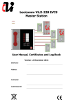
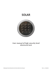
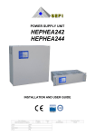
hiGhLiNe
WINDOW CONTROLS
INSTALLATION & USER MANUAL
SMOKE VENT
CONTROL SYSTEM
* enclosure design may vary
SVCS-1
software version: SVCS1r6
SVCS1r7
SVCS1r10
CERTIFICATE OF COMPLIANCE – SVCS-1
We the undersigned confirm that the SVCS-1 Simplified Ventilation Control
Panel conforms to relevant standards of construction and is fit for purpose,
which is, the control of automatic ventilation of habitable areas when smoke is
present in those areas.
Signed for and on behalf of Smoke Control Systems Ltd.
Ian Walton.............................................
Date: 04/01/2012
EQUIPMENT CONSTRUCTION STANDARDS
All control panels that we supply comply with the following harmonised
directives.
EN12101-10 Power Supplies
EMC (Electro-Magnetic Compatibility directive) Specifically
EN55014 EN50130 LVD (Low Voltage Directive)
We also use the applicable parts of BS5839 and EN54-2 (self declaration
method) for the design basis of our control equipment. Other directives are
still in the consultative stage and as yet are not fully harmonised with regard
to smoke control equipment.
CONTENTS
General Overview / Operation
3
Function
4
Installation
5
Cabling
6
Wiring Schematic
7
Connecting Actuator / Fire Alarm / Break Glass
8
Connecting Firemans Override
9
Connecting Smoke Sensors
10
Battery Information
11
Connecting Batteries / Mains Supply
12
Connections Overview
13
Testing
14
Fault Finding
17
Maintenance
18
Maintenance Schedule
19
SVCS-1 - USER MANUAL (version 2012)
2
GENERAL OVERVIEW
The SVCS series of smoke vent systems are easy to operate,
need very little maintenance and are "intelligent", in that for most
common failures (wiring, power supplies etc.) they will set some
form of warning alarm.
OPERATION
Once fully installed the system is totally automatic and provided
that the Red LED indicator is not on and there are no warning
sounds the system will upon receipt of an alarm input condition
(BMS Fire Alarm etc) open the smoke vents. The smoke vents will
stay fully open until the input condition (BMS, Fire Alarm, etc) has
been normalized, when the vents will close. Should you require the
vents to stay open after the alarm panel has been silenced (or deactivated) then a manual open command should be issued by use
of the manual key switch on the front panel.
TECHNICAL SPECIFICATION
Supply Voltage
Output Voltage
Output Current
SVCS-1 - USER MANUAL (version 2012)
230v AC
24v DC
2-10A
3
FUNCTION
PANEL KEYSWITCH – TOP PRIORITY
OPEN
All vents will open even
if smoke sensor or
break glass call points
are not activated.
AUTO
Will obey any remote
inputs.
CLOSE
Will close vents even if
smoke sensor or break
glass call points are
activated.
FIREMANS OVERRIDE SWITCH – TOP PRIORITY
OPEN
All vents will open even
if smoke sensor or
break glass call points
are not activated.
AUTO
Will obey any remote
inputs.
CLOSE
Will close vents even if
smoke sensor or break
glass call points are
activated.
Note: There is no priority between the keyswitches but a close (can be set to open by special
order) signal will take priority
SMOKE SENSOR – 2ND PRIORITY
ACTIVATED
All vents will open unless overridden
by FIREMANS OVERRIDE or
CONTROL PANEL SWITCH.
NOT ACTIVATED
Vents stay closed.
BREAK GLASS – 2ND PRIORITY
ACTIVATED
All Vents will open unless overridden
by FIREMANS OVERRIDE or
CONTROL PANEL SWITCH.
NOT ACTIVATED
Vents stay closed.
POWER FAILURE PROCEDURE
ON POWER FAILURE
Immediately
ACTION
Report fault.
After 11 hours
Opens Vents & shuts
down to minimum
power.
After 72 hours
System failure batteries
may not power system
back up.
SVCS-1 - USER MANUAL (version 2012)
RESULT
Report fault bleep and
red light every 4 secs.
Manual override of
vents by firemans
override switch only
reports fault by red light
every 10 secs. No
audible fault indicator.
Manual override of
vents may not be
achievable & batteries
may need replacing.
4
INSTALLATION
1
Unlock enclosure door using key provided.
2
Prepare holes or use pre-prepared knock outs for cable
entry. Fit cable glands (by others). Fix cabinet in place
(fixings by others).
3
Feed cables into cabinet.
4
Make cable connections as per attached wiring diagrams
(Make mains connection but do not turn on or connect
batteries until final checks are completed).
5
Ensure Cabinet is earthed (test using low value ohms
meter).
6
Connect blue connector (found on back of enclosure door) to
control board.
SVCS-1 - USER MANUAL (version 2012)
5
CABLING
Cabling of this panel should only be carried out by a competent
person and in accordance with all local and national standards and
legislation.
MAINS VOLTAGE
Two core + earth on a fused 3 amp spur or a separate circuit
protected by a 6amp MCB
VENT ACTUATORS
Two core + earth FP200 or equivalent for reverse polarity
actuators
Three core + earth FP200 or equivalent for common with drive
open- drive close
Three core + earth FP200 or equivalent for Belimo Actuators
Some actuators have a signal wire to indicate open close
status this MUST NOT be connected to the panel
Cable sizes must be calculated to ensure against excessive voltage drop
Voltage Drop (Vd) should not exceed 2 Volts
The formula is as follows; Vd = mV x A x m
Where;
A = total amperage of motors
m = length in metres
mV= millivolts per amp per metre figure taken from manufacturers cable data or use the
tables in the BS7671 (wiring regs.) document.
Example;
1 Supermaster Actuator = 2 Amps max load
Cable length m = 20 metres
1.5mm square cable == 29mV per amp per metre == 0.029Volts
(0.029 x 2) x 20 = 1.16V (Vd)
The above result is well within the limit of a 2 Volt voltage drop.
SVCS-1 - USER MANUAL (version 2012)
6
WIRING SCHEMATIC
HEALTHY
FAULT
AUTO
OPEN
HEALTHY
Green steady
CLOSE
Power On, System OK
FAULT
1 Bleep 4 sec interval
Flashes Green to Red
Power Off, batteries healthy
3 Bleeps &
Flashes Green to Red
Battery set 1 low disconnected or FS3 Blown
4 Bleeps &
Flashes Green to Red
Battery set 2 low disconnected or FS3 Blown
Continuous Sound
Activated
Rapid 2 tone
Firemans override operated
SVCS-1
VCS-S1
SMOKE VENT CONTROL SYSTEM
SVCS-1
SMOKE SENSOR SOUNDER (SSS)
ACTUATOR
SMOKE SENSOR (SSR)
** WIND SENSOR (WS1)
FIREMANS OVERRIDE (BG2/FOS)
HEALTHY
FAULT
AUTO
OPEN
HEALTHY
Green steady
CLOSE
Power On, System OK
FAULT
1 Bleep 4 sec interval
Flashes Green to Red
Power Off, batteries healthy
3 Bleeps &
Flashes Green to Red
Battery set 1 low disconnected or FS3 Blown
4 Bleeps &
Flashes Green to Red
Battery set 2 low disconnected or FS3 Blown
Continuous Sound
Activated
Rapid 2 tone
Firemans override operated
** RAIN SENSOR (RS1)
BREAK GLASS CALL POINT (BG1/S)
SVCS-1
VCS-S1
** THERMOSTAT (TS1)
230V AC FUSED SPUR
2-CORE
3-CORE
4-CORE
SVCS-1 - USER MANUAL
SMOKE VENT CONTROL SYSTEM
FIREMANS OVERRIDE (BG1/FOS)
FIRE ALARM SIGNAL
(VOLT FREE)
NOTE
CABLE SIZE MUST BE CALCULATED TO ENSURE VOLTAGE
DROP DOES NOT EXCEED 2V AT ALL MOTORS FULL LOAD
** AVAILABLE ONLY WITH A MODIFIED SVCS-1 CONTROL
BOARD. DESIGNED FOR NATURAL VENTILATION.
7
CONNECTING ACTUATOR(S)
CONNECTING BREAK GLASS
CONNECTING TO A FIRE ALARM
SVCS-1 - USER MANUAL (version 2012)
8
CONNECTING FIREMANS OVERRIDE
KEYSWITCH
CONNECTING FIREMANS OVERRIDE SWITCH
SVCS-1 - USER MANUAL (version 2012)
9
CONNECTING SMOKE SENSOR(S)
SVCS-1 - USER MANUAL (version 2012)
10
GENERAL BATTERY SET(S)
Note: When batteries are changed, the battery charger should be checked for voltage, which
should read approx. 27.6V, if different, please contact supplier.
VOLTAGE
27.6
Float Charge Voltage
25-27.6
U3 Warm to hot
22.1-24.9
U3 Warm to hot
21-22
U3 Warm to hot
14-21.9
May need replacing
<14
WILL NEED REPLACING
STATE
Batteries trickle Charging
fully charged
Batteries Charging +
50 – 95% charged
Batteries Charging +
10 - 49% charged
Batteries Charging +
<10% charged
Batteries Charging +
<5% charged
Batteries Charging +
<5% charged
The above is a guide only to the charge state of the batteries. There are a number of
conditions that can occur in the chemistry of batteries that can give erroneous indications by
using simple voltage measurement techniques. The only sure way of testing capacity is with a
known load over time and tracking the battery voltage over this time. If the batteries have
been abused by discharging them to totally flat and kept in that condition for an extended
period it is better to replace them as they are likely to be damaged and therefore may have a
much reduced capacity
SVCS-1 - USER MANUAL (version 2012)
11
SINGLE SET – 2AMP LOAD
SINGLE SET – 10AMP LOAD
CONNECTING THE MAINS
SVCS-1 - USER MANUAL (version 2012)
12
OVERVIEW
Note:
References to earthing of the cabinet refer to made to order panels only that are
using a metal cabinet.
SVCS-1 - USER MANUAL (version 2012)
13
TESTING
By far the most important thing about the use of this type of equipment is REGULAR
TESTING!
Testing has two major functions.
A The smoke sensors, alarm panel and vents are fully tested.
B Like all mechanical equipment the Vent Actuator motors need to be used
periodically so as to help prevent the build-up of internal corrosion and the
likelihood of an associated seizure of the mechanical parts.
Weekly visual (5 minutes)
Go to the panel and check for any warning/fault indications. If there is a fault then call
your local electrical engineer or call your supplier who will be pleased to help you.
Monthly test (15 minutes)
The Full Alarm testing should be carried out with the use of a "Smoke Aerosol". A 5
to 10 second spray at one of the smoke sensors will set off the alarm system. Each
month choose a different smoke sensor. Whilst the alarm is active check that all
Vents are open (Note ; in accordance with your cause and effect chart), reset the
alarm condition (you may have to do this a couple of times if the sensor under test
has not cleared the "smoke"). Next check that the manual key-switch will OPEN the
Vents (if fitted). After this switch back to AUTO, check again that there no fault
conditions and that concludes the test.
Annual
Once a year a full battery discharge test is advisable to check the condition of
the secondary power supply so that in the event of a fire the firemen have
sufficient open and close cycles available for their use. This should be done
by a specialist. Call your supplier for further information about annual service
contracts.
Log
The following are guidance notes around the mandatory maintenance and
testing requirements for both powered and natural smoke ventilation systems.
THE REGULATORY REFORM (FIRE SAFETY) ORDER 2005 states:
Maintenance 17:- (1) Where necessary in order to safeguard the safety of relevant persons
the responsible person must ensure that the premises and any facilities, equipment and
devices provided in respect of the premises under this Order or, subject to paragraph (6),
under any other enactment, including any enactment repealed or revoked by this Order, are
subject to a suitable system of maintenance and are maintained in an efficient state, in
efficient working order and in good repair.
BRITISH STANDARD BS 9999:2008 states:
Annex V (normative) Routine inspection and maintenance of fire safety installations
SVCS-1 - USER MANUAL (version 2012)
14
V.1 General
NOTE Fire safety installations comprise the items and elements of which examples are listed in Annex
J. It is essential for the safety of the occupants of a building that fire safety equipment (including passive
fire protection provisions) is inspected frequently. Although much of the inspection can be undertaken by
suitably trained personnel, a formal agreement should be made with the installer or the installer’s
representative to provide the regular inspection and testing described in the relevant British Standards
for individual fire safety installations. Unless temporary alternative fire safety systems can be put in
place, it might be appropriate for certain of the inspections carried out at three monthly or longer
intervals to be done outside normal working hours.
V.2 Daily inspections
V.2.1 General
The checks described in V.2.2 to V.2.6 should be undertaken daily. For premises with defined opening
times such as shops, theatres and cinemas, these checks should be undertaken prior to members of the
public entering the building.
V.2.2 Fire detection and alarm systems
N/A
V.2.4 Sprinkler systems
N/A
V.2.5 Fire door automatic release mechanisms
N/A
V.2.6 Portable fire extinguishers and hose reels
N/A
V.3 Weekly
V.3.1 General
In addition to the checks recommended in V.2, the checks described in V.3.3 to V.3.7 should be
undertaken once a week.
V.3.2 Fire detection and alarm systems
N/A
V.3.3 Sprinkler systems
N/A
V.3.4 Gaseous, foam and powder extinguishing systems
N/A
V.3.5 Smoke control systems for means of escape
Actuation of the system should be simulated once a week. It should be ensured that any fans and
powered exhaust ventilators operate correctly, smoke dampers close (or open in some systems), natural
exhaust ventilators open, automatic smoke curtains move into position, etc.
V.3.6 Evacuation lifts and fire-fighting lift installations
N/A
V.3.7 Fire hydrants
N/A
V.4 Monthly
V.4.1 General
In addition to the checks recommended in V.2 and V.3, the checks described in V.4.2 to V.4.9 should be
undertaken once a month.
V.4.2 Fire detection and alarm systems
N/A
V.4.3 Emergency and escape lighting systems
N/A
V.4.4 Gaseous, foam and powder extinguishing systems
N/A
V.4.5 Evacuation lifts and fire-fighting lift installations
N/A
V.4.6 Hose reels
N/A
V.4.7 Automatic opening doors
N/A
V.4.8 Doors on hold-open devices
N/A
V.4.9 Emergency and panic escape doors
N/A
SVCS-1 - USER MANUAL (version 2012)
15
V.5 Three-monthly
In addition to the checks recommended in V.2, V.3 and V.4, the actuation of all smoke control systems
should be simulated once every three months. All zones should be separately tested and it should be
ensured that any fans and powered exhaust ventilators operate correctly, smoke dampers close (or
open in some systems), etc.
V.6 Six-monthly
V.6.1 General
In addition to the checks recommended in V.2, V.3, V.4 and V.5, the checks described in V.6.2 and
V.6.3 should be undertaken once every six months. Arrangements should be made for six- monthly
inspections and tests to be carried out by competent persons on the fire detection and alarm systems,
the sprinkler systems, any extinguishing systems, the emergency and escape lighting systems and the
fire-fighting lift, for any defects found to be logged and the necessary action taken, and for certificates of
testing to be obtained.
V.6.2 Fire doors
N/A
V.6.3 Fire mains
N/A
V.7 Yearly
NOTE Attention is drawn to the testing and inspection requirements of BS 7671.
In addition to the checks recommended in V.2, V.3, V.4, V.5 and V.6, arrangements should be made for
annual inspections and tests of the following to be carried out by competent persons, for any defects to
be logged and the necessary action taken, and for certificates of testing to be obtained:
.
d) smoke ventilators and smoke control systems;
Whilst this is a comprehensive assessment (and is for general guidance only), it should be noted that
manufacturers have their own maintenance and testing requirements and if different these should be
followed. For full guidance you should read the Regulatory Reform Order 2005 along with BS9999 to
satisfy that you are meeting your statutory obligations.
SVCS-1 - USER MANUAL (version 2012)
16
FAULT FINDING
FAULT INDICATOR
One bleep at four second interval
Rapid 2 tone
Two x 2 tone
Three bleeps @ two second interval
Four bleeps @ two second interval
Continuous sound
FAULT
Mains Power failure or FS1 blown
(315mA T)
Override switch activated
(open – close)
Terminating resistor or FS4 blown
(125mA T)
Battery set 1 low or FS3 blown
(10A T)
Battery set 2 low or FS2 blown
(10A T)
Break glass or Smoke Sensor
activated
Red LED will be illuminated during each fault also the fault/reset relay will be
active allowing the fault to be monitored remotely.
SVCS-1 - USER MANUAL (version 2012)
17
MAINTENANCE
CONTROL PANEL
Control Panel should be maintenance free with the exception of the Batteries.
BATTERIES
Between 3 to 5 years the backup batteries will need to be changed.
SENSORS, SWITCHES & ACTUATORS
Refer to individual instructions for any attached components of this system.
If you are in any doubt about any of the above procedures etc. then do give us
a call and we will help you.
SVCS-1 - USER MANUAL (version 2012)
18
MAINTENANCE SCHEDULE
DATE
WORK DONE
COMPANY
INITIALS SIGNATURE
The above testing should be entered into a log with the sensor number (or floor level), date of testing
and signed. The log should be kept in a safe place near the main control panel so any maintenance may
be recorded. These are purely our recommendations and we would advise you contact your local fire
officer who will only be too pleased to analyse the building and give his own recommendations as to
testing and safety etc. Please use table on back page of this booklet and leave in or by the control
panel.
SVCS-1 - USER MANUAL (version 2012)
19