1
US 20120083789A1
(19) United States
(12) Patent Application Publication (10) Pub. No.: US 2012/0083789 A1
BLAKEMORE et al.
(54)
METHOD OF IMPLANTING A PROSTHESIS
DEVICE USING BONE CEMENT IN LIQUID
FORM
(75) Inventors:
David BLAKEMORE, Warsaw, IN
(43) Pub. Date:
Apr. 5, 2012
(51)
Publication Classi?cation
Int CL
A61B 17/58
(2006.01)
(52)
US. Cl. ........................................... .. 606/93; 606/92
(57)
(US); Keith PENNINGTON,
ABSTRACT
_
_
_
_
Warsaw, IN (Us); Shaun PITTS,
Warsaw’ IN (Us)
The present invention relates to a method of 1mplantmg~a
prosthesis dev1ce 1n a subject. In one embodlment, th1s
(73) Assignee:
VOT, LLC, Warsaw, IN (U S)
cement in liquid form to a bone-implant interface region, the
bone-implant interface region including a region between the
(21) APP1- NOJ
13/249,044
prosthesis device; and (iii) contacting the bone cement to the
method mvolves: (1) providmg a prosthesis dev1ce to be
attached to an exposed surface of a bone; (ii) applying bone
exposed surface of the bone and an outer surface of the
exposed surface of the bone and the outer surface of the
-
_
(22) Flled'
ro sthesis device under conditions effective to allow the bone
sep' 29’ 2011
IcDement to cure, thereby resulting in attachment of the pros
thesis device to the bone of the subject. The present invention
Related U_s_ Application Data
(60)
Provisional application No. 61/389,193, ?led on Oct.
1, 2010.
also relates to a kit for implanting a prosthesis device in a
subject, a method of performing a joint arthroplasty surgical
procedure, and other methods of using bone cement in liquid
form.
Patent Application Publication
Apr. 5, 2012 Sheet 1 0f 10
US 2012/0083789 A1
.QE
w
Patent Application Publication
Apr. 5, 2012 Sheet 2 0f 10
US 2012/0083789 A1
Patent Application Publication
Apr. 5, 2012 Sheet 3 0f 10
FiGi 3
US 2012/0083789 A1
Patent Application Publication
Apr. 5, 2012 Sheet 4 0f 10
FIG. 4
US 2012/0083789 A1
Patent Application Publication
Apr. 5, 2012 Sheet 5 0f 10
US 2012/0083789 A1
Patent Application Publication
Apr. 5, 2012 Sheet 6 0f 10
FIG. 6
US 2012/0083789 A1
Patent Application Publication
Apr. 5, 2012 Sheet 7 0f 10
FIG. ‘2’
US 2012/0083789 A1
Patent Application Publication
Apr. 5, 2012 Sheet 8 0f 10
US 2012/0083789 A1
Patent Application Publication
Apr. 5, 2012 Sheet 9 0f 10
FIG. Q
US 2012/0083789 A1
Patent Application Publication
Apr. 5, 2012 Sheet 10 0f 10
Tima in m bail’: {min}
FIG‘ w
US 2012/0083789 A1
Apr. 5, 2012
US 2012/0083789 A1
METHOD OF IMPLANTING A PROSTHESIS
DEVICE USING BONE CEMENT IN LIQUID
FORM
CROSS-REFERENCE TO RELATED
APPLICATIONS
[0001] This application claims priority bene?t of US. Pro
visional Patent Application Ser. No. 61/389,193, ?led Oct. 1,
2010, the disclosure of Which is hereby incorporated by ref
erence herein in its entirety.
FIELD OF THE INVENTION
[0002] The present invention generally relates to the use of
bone cement in a liquid form in joint arthroplasty.
BACKGROUND OF THE INVENTION
[0003] During the resurfacing techniques used in joint
[0007] In another aspect, the present invention relates to a
kit for implanting a prosthesis device in a subject. The kit
includes: (i) a prosthesis device comprising a body having at
least one port through Which bone cement in liquid form can
be applied to a bone-implant interface region, Where the
bone-implant interface region includes a region betWeen an
exposed surface of a bone of the subject and an outer surface
of the prosthesis device; and (ii) a user manual comprising
instructions for applying bone cement in liquid form to said
bone-implant interface region.
[0008]
In another aspect, the present invention relates to a
method of performing a joint arthroplasty surgical procedure.
This method involves the folloWing steps: (i) providing a
prosthesis device for use in a joint arthroplasty surgical pro
cedure and to be attached to an exposed surface of a bone of
a subject, Where the prosthesis device includes at least one
portal; and (ii) directing bone cement in liquid form through
the at least one portal to a bone-implant interface region,
arthroplasty, the honey surface is prepared using saW cuts,
Where the bone-implant interface region includes a region
mills or burs, and a metal or plastic insert is bonded to the
betWeen the exposed surface of the bone and an outer surface
prepared surface of the bone using a bone cement such as poly
of the prosthesis device, thereby resulting in attachment of the
methyl methacrylate (PMMA) in a paste or dough form. The
bone cement is applied to the surface of the resected bone, the
underside of the implant, or both and the implant is put in
place. The bone cement is in the form of a thick bonding agent
that is easily handled since it can be kneaded into shape and
pressed into place by hand. At the stage it is used it also does
prosthesis device to the bone of the subject.
not stick to the surgeons tools or gloves Which makes it even
[0009]
In a further aspect, the present invention relates to a
method of reattaching loose implants arthroscopically using
bone cement in liquid form, as described herein.
[0010] In another aspect, the present invention relates to a
method of performing a bone-to-bone fusion using bone
cement in liquid form, as described herein.
Less viscous forms of the bone cement also are problematic
because they can leak or have unreasonable curing times,
[0011] The present invention provides a method of joint
arthroplasty that involves using a less viscous or liquid
cement than is the traditional bone cement currently used in
the art. The present invention provides a bone cement having
the ability to ?ll the bone voids more readily and therefore
provide a stronger attachment to the bone. Further, the present
invention provides a technique to apply loW viscosity cement
leading to ineffective or poorly setting implants. In addition,
to the needed area.
this sort of thinner bone cement is dif?cult to contain and
adheres to most surfaces it comes in contact With, making it
a loW viscosity cement to the needed area. The use of the bone
easier to handle. However, there are signi?cant limitations in
using such bone cement for joint arthroplasty. For example, it
is di?icult to insert the bone cement into narroW or tight
spaces in and around the implant area. Further, the bone
cement is not easily conformable to complex geometries.
[0012]
The present invention provides a technique to apply
cement (e.g., PMMA) in this form is typically discouraged
dif?cult for surgical teams to use in joint arthroplasty proce
dures.
[0004] There is a need for a method for using bone cement
in a liquid form in joint arthroplasty, Where the bone cement
is less viscous (e.g., in a liquid cement form) than the tradi
tional bone cement currently and regularly used in the art.
There is also a need for a bone cement that has the ability to
?ll the bone voids more readily and provide better adhesive
since it is dif?cult to handle in the surgical setting. HoWever,
the present invention solves the issues of handling the loW
viscosity bone cement by providing a system that includes the
choice of cement, mixing, transfer, effects of environmental
factors, stages and application of a liquid cement in a Way that
bene?ts the patient and the surgeon.
properties as it is applied to joint arthroplasty.
[0005] The present invention is directed to overcoming
this invention Will become apparent from the folloWing
detailed description of the various aspects of the invention
these and other de?ciencies in the art.
SUMMARY OF THE INVENTION
[0013]
These and other objects, features, and advantages of
taken in conjunction With the accompanying draWings.
BRIEF DESCRIPTION OF THE DRAWINGS
method of implanting a prosthesis device in a subject. This
[0014] For the purpose of illustrating aspects of the present
invention, there are depicted in the draWings certain embodi
method involves the folloWing steps: (i) providing a prosthe
ments of the invention. HoWever, the invention is not limited
sis device to be attached to an exposed surface of a bone of a
to the precise arrangements and instrumentalities of the
[0006]
In one aspect, the present invention relates to a
subject; (ii) applying bone cement in liquid form to a bone
embodiments depicted in the draWings. Further, if provided,
implant interface region, Where the bone-implant interface
like reference numerals contained in the draWings are meant
to identify similar or identical elements.
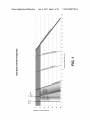
[0015] FIG. 1 is a graph chart shoWing bone cement prop
region includes a region betWeen the exposed surface of the
bone and an outer surface of the prosthesis device; and (iii)
contacting the bone cement to both the exposed surface of the
bone and the outer surface of the prosthesis device under
erties for Palacos LV cement, including set times and inject
ability ranges.
resulting in attachment of the prosthesis device to the bone of
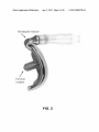
[0016] FIG. 2 is a photograph of a femoral implant and 130
degree injector used in one embodiment of a method of the
the subject.
present invention.
conditions effective to alloW the bone cement to cure, thereby
Apr. 5, 2012
US 2012/0083789 A1
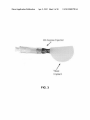
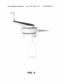
[0017] FIG. 3 is a photograph of a tibial implant and 45
degree injector used in one embodiment of a method of the
present invention.
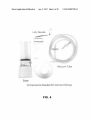
[0018] FIG. 4 is a photograph of various components used
for cement mixing in one embodiment of a method of the
present invention.
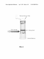
[0019]
FIG. 5 is a photograph of a lid being connected to a
vacuum system using a vacuum tube in accordance With one
embodiment of a method of the present invention.
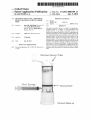
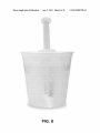
[0020] FIG. 6 is a photograph of one vieW ofa standard 10
mL syringe connected to a lure adapter on the side of a mix
system suitable for use in one embodiment of a method of the
present invention.
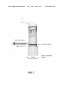
[0021] FIG. 7 is a photograph of one vieW ofa standard 10
mL syringe connected to a lure adapter on the side of a mix
system suitable for use in one embodiment of a method of the
present invention. This vieW demonstrates that pulling the
plunger on the syringe Will alloW the syringe to become ?lled
With the cement.
[0022] FIG. 8 is a photograph of one vieW ofa standard 10
mL syringe in a chilled saline bath in accordance With one
embodiment of a method of the present invention.
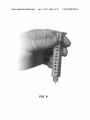
[0023] FIG. 9 is a photograph of one vieW ofa standard 10
to joint prosthesis devices for small joints, suitable devices
can be those used for a PIP joint (?nger), an MCP joint
(knuckle), a DIP joint (?nger), a CMC joint (thumb), and a
metatarsophalangeal joint (toe).
[0028] Various types of bone cement knoWn in the art can
be used in the methods of the present invention, as long as
such bone cement is con?gured to be in liquid form in accor
dance With the present invention. In one embodiment, the
bone cement in liquid form can be, Without limitation, poly
(methyl methacrylate) (PMMA) at a viscosity of about
10,000 centipoise (cP) or less, about 9,000 cP or less, about
8,000 cP or less, about 7,000 cP or less, about 5,000 cP or less,
about 4,000 cP or less, about 3,000 cP or less, about 2,500 cP
or less, about 2000 cP or less, about 1500 cP or less, about
1000 cP orless, about 500 cP or less, about 250 cP or less, and
the like.
[0029] In one embodiment of the method of the present
invention, the applying step includes introducing the bone
cement in liquid form to the bone-implant interface region
through at least one port of the prosthesis device.
[0030] In another embodiment of the method of the present
invention, prior to the applying step, the method further
mL syringe being held for monitoring of drip rate or How of
includes conducting a viscosity test on the bone cement to
determine a viscosity range at Which the bone cement is in
cement from the syringe during one embodiment of a viscos
ity drip test in accordance With one embodiment of a method
liquid form suitable for applying to the bone-implant inter
of the present invention.
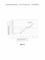
[0024] FIG. 10 is a graph shoWing the results of an experi
ment to test the effect of chilling PMMA bone cement poly
[0031] A suitable viscosity test for use in the present inven
tion can include, Without limitation, a drip test effective to
measure the rate of How, Where the viscosity test is suitable to
meriZation to prolong inj ectability. The graph shoWs recorded
provide a beginning and ending point for applying the bone
viscosity (cP) over a period of time in an ice bath (minutes) for
cement in liquid form. In one embodiment, for example, the
beginning point can be a rate of How such as 2 drips/ second,
a PMMA bone cement polymerization reaction.
DETAILED DESCRIPTION OF THE INVENTION
[0025]
The present invention provides a method of implant
ing a prosthesis device in a subject. This method involves the
folloWing steps: (i) providing a prosthesis device to be
face region.
1 drip/second, and l drip/5 seconds, and the like. In another
embodiment, for example, the ending point can be a rate of
How such as less than about 1 drip/ 5 seconds, less than about
1 drip/l0 seconds, and no apparent drips/5-l0 seconds.
[0032] Another suitable viscosity test for use in the present
a region betWeen the exposed surface of the bone and an outer
invention can include, Without limitation, a test that involves
measuring migration of the bone cement on a test surface
under conditions effective to determine When the bone
cement is in a liquid form having a suitable viscosity range for
surface of the prosthesis device; and (iii) contacting the bone
said applying step.
cement to both the exposed surface of the bone and the outer
surface of the prosthesis device under conditions effective to
alloW the bone cement to cure, thereby resulting in attach
ment of the prosthesis device to the bone of the subject.
[0033] Yet another suitable viscosity test for use in the
present invention can include, Without limitation, a test that
attached to an exposed surface of a bone of a subject; (ii)
applying bone cement in liquid form to a bone-implant inter
face region, Where the bone-implant interface region includes
[0026] The method of the present invention is suitable for
use With all types of prosthesis devices. For example, a suit
able prosthesis device can include, Without limitation, a joint
prosthesis device for replacing or partially replacing a joint
such as a knee, a hip, a shoulder, an ankle, an elboW, a spinal
disc, a cervical disc, and a small joint. Other suitable
examples of prosthesis devices for use in the method of the
present invention can include, Without limitation, devices
involves measuring the change in temperature of the bone
cement under conditions effective to determine When the
bone cement is in a liquid form having a suitable viscosity
range for said applying step.
[0034] In another embodiment of the method of the present
invention, after the applying step and/ or after the contacting
step, the method further includes subjecting the bone cement
to curing conditions effective to decrease the setting time of
the implanted prosthesis device. In a particular embodiment,
the subjecting can include, Without limitation, adding heat to
having all or portions of a tibial component, a femoral com
ponent, a patellar component, an acetabular component, a
glenoid component, a humeral component, a talar compo
the bone cement. As a suitable example, the heat can be added
using saline at a temperature of betWeen about 80 and 100
nent, an ulnar component, or a fusion cage component. In one
[0035] Various means for applying the bone cement in liq
uid form in accordance With the methods of the present inven
tion can be used. For example, in one embodiment, the bone
cement in liquid form is applied to the bone-implant interface
embodiment, the prosthesis device can include a body having
at least one port through Which the bone cement in liquid form
is applied to the bone-implant interface region.
[0027] Other suitable examples of joint prosthesis devices
can be those used for a partial knee replacement, a patello
femoral replacement, or a total knee replacement. With regard
degrees F.
region using a delivery instrument. Those of ordinary skill in
the art, in vieW of the present speci?cation, can determine
various types of delivery instruments that are suitable for use
Apr. 5, 2012
US 2012/0083789 A1
in the methods of the present invention. A syringe is a suitable
example of a delivery instrument for use in the method of the
present invention. Those of ordinary skill in the art can readily
determine the various types and siZes of syringes that can be
used in the methods of the present invention. While not
intending to be limiting, in a particular example, the syringe
can be con?gured to contain a volume of liquid of up to about
50 cubic centimeters (cc).
[0036] In one embodiment, an injector adapter is used to
facilitate application of the bone cement in liquid form from
the delivery instrument to the bone-implant interface region.
In a particular embodiment, the prosthesis device includes a
body having at least one port through Which the bone cement
in liquid form is applied to the bone-implant interface region,
With the injector adapter being con?gured to couple the inj ec
tion instrument to the at least one port of the prosthesis device.
[0037]
In another embodiment of the method of the present
invention, prior to and/or during the applying step, the
method further includes delaying curing of the bone cement
from its liquid form to its cured form. In a particular embodi
ment, this delaying step can include maintaining the bone
cement in liquid form at a temperature range such as, but not
limited to, a temperature range of betWeen about 0° F. and
about 40° F., betWeen about 10° F. and about 40° F., betWeen
about 15° F. and about 40° F., betWeen about 20° F. and about
40° F., betWeen about 25° F. and about 40° F., betWeen about
30° F. and about 38° F., betWeen about 32° F. and about 35° F.,
and the like. In another particular embodiment, this delaying
step includes maintaining the bone cement at a temperature of
not more than about 0° F. Those of ordinary skill in the art, in
vieW of the speci?cation, Would readily understand hoW to
achieve the delaying step. While not intending to be limiting,
in a particular example, the delaying step can include main
taining the bone cement in crushed ice, a mixture of ice and
Water, refrigerator-chilled saline, and/or freeZer-chilled
saline.
[0038] Suitable means for carrying out the maintaining step
can include, for example, incubating the bone cement in
liquid form in an ice bath or chilling the bone cement in liquid
form using chilled saline. In a particular embodiment, the
incubating is for a period of not more than about 25 minutes
and/ or not more than betWeen about 10 and about 25 minutes
prior to applying the bone cement in liquid form to the bone
implant interface region.
[0039] The present invention also provides a kit for
implanting a prosthesis device in a subject. The kit includes:
(i) a prosthesis device comprising a body having at least one
port through Which bone cement in liquid form canbe applied
to a bone-implant interface region, Where the bone-implant
interface region includes a region betWeen an exposed surface
of a bone of the subject and an outer surface of the prosthesis
device; and (ii) a user manual comprising instructions for
applying bone cement in liquid form to said bone-implant
interface region.
[0040] The kit of the present invention can further include
an injection instrument for applying the bone cement in liquid
form through the at least one port of the prosthesis device.
Suitable examples of injection instruments are as disclosed
herein and as readily understood by those of ordinary skill in
the art in vieW of the present speci?cation. The kit of the
present invention can further include an injector adapter con
?gured to couple the injection instrument to the at least one
port of the prosthesis device.
[0041]
The present invention further provides a method of
performing a joint arthroplasty surgical procedure. This
method involves the folloWing steps: (i) providing a prosthe
sis device for use in a joint arthroplasty surgical procedure
and to be attached to an exposed surface of a bone of a subject,
Where the prosthesis device includes at least one portal; and
(ii) directing bone cement in liquid form through the at least
one portal to a bone-implant interface region, Where the bone
implant interface region includes a region betWeen the
exposed surface of the bone and an outer surface of the
prosthesis device, thereby resulting in attachment of the pros
thesis device to the bone of the subject.
[0042] The present invention also provides a method of
reattaching loose implants arthroscopically using bone
cement in liquid form, as described herein. Those of ordinary
skill in the art, in vieW of the present speci?cation, can readily
determine the steps involved in perform this method.
[0043] The present invention further provides a method of
performing a bone-to-bone fusion using bone cement in liq
uid form, as described herein. Those of ordinary skill in the
art, in vieW of the present speci?cation, can readily determine
the steps involved in perform this method.
[0044]
Traditional bone cement (e.g., PMMA) used in joint
arthroplasty is normally used in a doughy state. Manufactur
ers of traditional bone cement provide descriptions of the
normal Working phase: a doughy state that no longer sticks to
a gloved hand. This state is accurately de?ned and predicted
by existing ambient temperature charts. HoWever, the manu
facturers do not characterize “injectability” as it is done With
respect to the present invention. Therefore, the information
that bone cement manufacturers provide does not apply for
application in a liquid state. What descriptions there are for
using cement in a liquid state only apply to vertebroplasty and
other vertebra augmentation procedures Where the cement is
injected With high pressure directly into the trabecular struc
ture of the bone itself, not betWeen implants and bone as
Would be relevant to joint replacement surgery. For example,
the Caspari group describes a method of injecting liquid
cement underneath the implant but not through the implant.
[0045] The present invention provides, inter alia, a method
that involves the application of cement in a liquid state that is
superior to “thumb -packing” a standard doughy-state cement
because it greatly increases the interdigitation of the cement
into the trabecular structure of the bone beneath the implant.
This results in greater structural stability, Which should in turn
lead to feWer implant failures due to looseningia leading
cause of revision reoperations. By enabling the surgeon to
con?dently inject cement at a loWer viscosity, the present
invention helps to alleviate this and other problems relating to
joint arthroplasty.
[0046]
It is provided that a loW viscosity cement Would
alloW for a better mechanical bond to the trabecular structure
of bone and the implant surface by providing greater inter
digitation and penetration than the standard method of apply
ing cement in a doughy state. It is also provided that this liquid
form of the cement could provide for greater adhesive prop
erties as seen in its properties at this stage seen in the inability
to handle this liquid cement easily as it sticks to any surface it
comes into contact With. It is further provided that liquid
cement can be injected through small openings as opposed to
a doughy cement Which is applied to the surface to be bonded
?rst and then the surfaces joined. In the present invention, the
implants can be set in place and the cement injected in the
space betWeen the component and the host bone. Unlike the
Apr. 5, 2012
US 2012/0083789 A1
present invention, the prior art does not provide current guide
lines for injecting cement through a syringe relevant foruse in
orthopedic arthroplasty.
[0047]
inj ectability of the cement. Some distinguishing characteris
tic of the implant devices to be used With this process is that
they have portals that alloW for an interface of a pressurization
system and channels to direct the How of the injected cement.
A distinguishing characteristic of the injectable cement sys
tem is that it is used early in the mixing and curing process of
the cement so that it is at a loW viscosity upon applicationi
and the application of the cement takes place When the
implant is already in place. Specialized implant design and
injecting instrumentation can be used along With cement in
this state, Which may otherWise be too thin to handle and
utiliZe effectively.
Implants are developed With dams that limit extru
sion and Which also guide the How. Special interlocking
geometries on the under surfaces of implants are also devel
oped to Work With liquid cementithese geometries alloW
cement to How into and up around comers of the implant in
order to get a stronger mechanical lock. Injectors Which
attach to portals on the implant on one end and syringes on the
other are developed for a simple cement injection protocol.
These features and instruments are neW to joint replacement
implant techniques.
[0049]
The present invention does not formulate a neW kind
of cement, but instead in one embodiment takes advantage of
regularly available PMMA bone cement that is used at an
earlier stage of the curing process. Cement applied With Liq
uiFlo technology of the present invention is chemically and
structurally the same as the original commercial bone cement
used as there is no addition or removal of any ingredients and
there is no change of the chemical makeup of the cement in
any Way.
[0050]
In one embodiment, this technique description of
the present invention outlines the parameters needed to alloW
for an inj ectable cement to be used in the operating room. For
example, it includes preparation, mixing, setting times and
establishes injectability ranges for use Within a surgical
arthroplasty procedure utiliZing PMMA cement in its liquid
state.
Step 1: Mixing the Cement
[0051]
sterile Water at 32-35 degrees to suspend its state of viscosity
for subsequent use.
The present invention, in one embodiment, provides
tWo parts. The ?rst part is the implant devices With Which this
liquid injection technique can be used With, and the second
part is the application and methodology used to control the
[0048]
der of the mixed cement can be optional set into an ice bath of
Step 4: Cement Delivery or Injection
[0054]
amount of cement is delivered to the underside of the
implants.
[0055]
according to the manufactures recommendations (30-60 sec
The inj ectability range of the cement is very impor
tant to identify: a neW phase is de?ned in Which cement can be
consistently pushed through injectors While completely ?ll
ing the necessary boney voids and the geometries of the
implant used to attain ridged ?xation.
[0056] Examples of set times and injectability ranges are
shoWn for Palacos LV cement in the graph of FIG. 1.
[0057] Important factors that affect injectability and set
time include: (i) times of inj ection after initial mix; (ii) ambi
ent temperature; (iii) addition of or subtraction of heat on the
loaded syringe for different lengths of time; and (iv) bolus
(different setting volume/Waiting volume) effects.
[0058]
Mixes generally take around the same time to com
plete and syringes are ?lled immediately after (mixes Were
usually complete at 1:15 min after initial monomer-cement
contact and transferred to syringes at 2:15).
[0059] Viscosity is used as a metric for determining another
termi“injectability” Which is de?ned as the cement’s vis
cosity as being beloW a certain value that is both easy to inject
out of a standard syringe and spread doWn the length of a
femoral partial knee implantimore viscous and it Would not
?ll the implant but instead form a ball near the site of inj ection
that pushes the implant out of place. The viscosities for dif
ferent temperatures and bolus siZes are given as a function of
time from mix for incorporation into a surgical procedure.
Higher temperatures lead to faster set times, but also lead to
increased viscosity early on, Which limits injectability.
Ranges are given for stages of injectability for both tibial and
femoral components, as Well as ?nal set times for different
setting-environment temperatures.
[0060] A procedure called the “drip-test” is a method to
determine the ideal time for injection. It corresponds to a
viscosity of around 500 to 1000 centipoise, and is easy to
reproduce in an operating room environment. The cement is
considered injectable When 1 drip of curing cement per sec
ond comes from tip of a plunger-less 10 cc syringe When held
upright.
Injectability
The PMMA cement is vacuum mixed in a container
onds).
The syringe is attached to the implant via a propri
etary adapter and the plunger is pressed until the prescribed
[0061] Viscosity Was determined by the Hagen-Poiseuille
equation,
Step 2: Transfer of Mixed Cement to Injection
Syringe
[0052]
SpLQ
AP:
m4
The mixed cement is transferred to an appropriate
siZed syringe through a transfer port or by pouring the liquid
cement directly into the large open end of the syringe.
Step 3: Determination of Inj ectability of the Cement
and Suspension of Cement Curing
[0053] A drip test is performed in Which a separate cement
?lled syringe is held vertically and the rate at Which the
cement drips from the syringe tip is monitored. The remain
Which shoWs relationship betWeen pipe siZe (L, r), ?oW rate
(Q), pressure difference (AP), and viscosity ([1) for non-tur
bulent ?oW through a pipe.
[0062]
When modeled at the end of the luer syringe, this
equation gives viscosity as a function of Weight applied (to
create pressure difference AP) and velocity of plunger (to
calculate ?oW rate Q). The ?nal equation is reached When
modeled at the end of a luer syringe and a force of 10 pounds
Apr. 5, 2012
US 2012/0083789 A1
is applied to the plunger of a 10 cc syringe to create the
pressure differential. This is factored in to the u-0.0684/Vx
equation.
[0063]
Bone cement is considered “injectable” When the
viscosity is below a level Where the cement can be comfort
ably pushed from a syringe and ?ll the volume underneath the
implant While not pushing the implant out of place.
[0064] Times are de?ned Where injectability “ends” for
different ambient temperatures With standard mix conditions.
These are outlined on the graph beloW, for Palacos LV.
[0065] The cement Working stages and setting set times are
important to knoW because the surgeon is concerned With the
length of time needed to hold the knee in place While the
cement sets. It is important to note that most practicing sur
geons are trained to hold the limb in position for as long as it
takes the cement to cure. Under standard mixes and “thumb
pack” technique this is typically 10-15 minutes. The standard
of care relies on these times and a bolus of cement from the
order to ensure full cement ?ll underneath the implant and to
minimize the amount of uncontrolled extrusion. The proce
dure should also outline the time required for the cement to
cure suf?ciently to avoid displacement of the implant While
the ?nal steps are performed.
[0072] One embodiment of a method of the present inven
tion can include, for example, the beloW steps as contem
plated during a surgical procedure and in a surgical setting for
a partial knee procedure, as follows:
I. Pre-Surgery
[0073] If chilled saline is unavailable, prepare an ice bath
before the procedure starts, and place a 1 liter sterile saline
container Within the ice bath. Chilled saline Will be used later
in the procedure to chill mixed cement. Ensure that 2 boxes of
cements such as Palacos LV or Osteobond are available for
surgery.
original mix being monitored for curing outside the Wound. It
ll. Pre-Cementing Steps
has been found that this method may not be reliable since a
bolus of cement cures at a different rate than a mantle of
[0074]
cement that is located betWeen the implant and the ho st bone.
If the cement does not set properly, it could lead to malposi
tioning or early cement failure. It is important to knoW setting
times in all conditions so that company representatives in the
room may ansWer any questions should complications arise.
tion, the folloWing steps:
[0075] l.After drilling three (3) 3 .2 mm holes into the tibial
plateau, lavage and dry area to remove bone and other debris
that could prohibit free How of cement and adhesion to the
prepared bony surface.
[0076]
lcing
[0066] Since the curing reaction is largely heat-dependent,
cooling the cement sloWs the reaction. Placing the ?lled
syringe into an ice-bath after ?lling Would therefore be useful,
speci?cally in Warmer Operating Room temperatures Where
the injectability phase ends just over 4 minutes after mix,
leaving little time for the procedure to be completed.
[0067]
The addition of the ice bath: removes ambient tem
perature variability, controls reaction time, extends inject
ability range, and 32 degrees is easy to reproduce. This is a
Pre-cementing steps can include, Without limita
2. Dry area With gauZe or hydrosorb 4x4 and remove
just before inserting implants into proper position.
[0077]
3. Place injector(s) in implants on back table to
expedite cementing process (see FIG. 2 and FIG. 3).
[0078] 4. Ensure surgeon is ready and has implants and
injectors in place on back table prior to mixing.
[0079] 5. Pour enough chilled saline into a container to
completely cover cement-?lled 10 mL syringe. Use needle
cap to close end of syringe.
[0080] 6. Have four (4) standard 10 mL syringes available
for cementing technique.
value-added simple step to incorporate into the procedure.
[0068]
Ill. Cement Mixing
lcing Was found to sloW injectability for up to 15
minutes. After 15 minutes, the reaction has progressed
[0081]
enough to increase the rate of becoming more viscous to a
tation, the folloWing steps:
point Where it Would cause signi?cant changes to the inject
ability of the cement.
[0069] Cement is a self-curing polymer, it should be noted
that the reaction can be sloWed by icing but not stopped. lcing
sloWs the reaction and maintains the inj ectability state of the
[0082]
Cementing mixing steps can include, Without limi
1. Remove cement mixer and cement from any
packaging. Examples of various components needed for
cement mixing are shoWn in FIG. 4.
[0083] 2. Connect vacuum system to Lid using vacuum
tube (see FIG. 5).
cement When it entered the ice bath for up to 15 minutes.
When the cement is removed from the ice the curing times are
delayed and care should be taken to ensure full cure. With the
addition of a Warm Water lavage after implantation, these
mer When ready and begin mixing cement immediately. Mix
delays are negligible.
[0070] Different holding volumes (before injection) Were
LiquiFloTM cementing procedure. Note: Do not mix vigor
considered, as smaller boluses Were previously shoWn to have
longer set times. This Was tested to determine if the holding
[0085] 4. Once mix is complete, pull the vacuum tube from
the mixer lid before proceeding to the next step.
bolus effects changed injectability. The results did not shoW
any appreciable effect on inj ectability. Set times outlined here
[0084]
3. Pour poWder into cement base ?rst. Add mono
for 45 seconds. Do not alloW poWder and monomer to sit for
any length of time before mixing, as time is critical in the
ously.
IV. Syringe Transfer
are for setting boluses of 2 cc each Which is similar to the
amount seen betWeen the implant and the host bone for a
[0086]
partial knee replacement. Bolus effects had no noticeable
folloWing steps (Without limitation):
Syringe transfer can be performed according to the
effect on inj ectability, as a holding volume of l 0 cc seemed to
[0087]
have the same injectability as 5 cc.
adapter on the side of the mix system (see FIG. 6). Once
[0071] The surgical procedure for any arthroplasty using
connected, tWist the bottom of the cement base so that the
bottom of the cement mixing shelf loWers, and alloWs cement
to How through the port.
injecting liquid cement should include this information
depicting the optimal time to inject the PMMA cement in
1. Connect a standard 10 mL syringe to the lure
Apr. 5, 2012
US 2012/0083789 A1
[0088] 2. Pull the plunger on the syringe to 10 mL (see FIG.
7). Cement Will folloW the plunger and ?ll the syringe. Do not
pull further than the 10 mL mark, as this can disengage the
cement. Since the speed of the reaction is dependent on tem
perature, the time that the cement remains in a desirable state
can be prolonged by arti?cially decreasing the temperature.
plunger. Complete for all four (4) syringes.
In order to more closely study the effect of chilling the cement
[0089] 3. Once the four (4) syringes are full, complete the
“Drip Test” With one of the syringes, then place one (1)
syringe in chilled saline bath and give surgeon one (1) full 10
to prolong the previously de?ned “injectability” state this
mL syringe (see FIG. 8).
V. Viscosity Drip Test
[0090]
A viscosity drip test can be performed according to
the folloWing steps (Without limitation):
[0091]
1. This syringe gauges the cement viscosity through
series of tests Was carried out to appropriately de?ne a pro
tocol and limitations regarding chilling cement in a clinical
situation.
[0102] The objectives of this study are to de?ne a limit, if
any, to the effectiveness of using an ice bath to limit the
progression of the reaction of curing PMMA cement and
extend the amount of time it is considered to be injectable.
the drip test. Hold the syringe vertically, and alloW cement to
Introduction
freely drip from the luer noZZle.
[0092] 2. Monitor the drip rate or How of the cement from
the 10 mL. syringe With no plunger installed as shoWn in FIG.
9.
[0093] 3. FloW of cement Will turn to a perceptible dripping
rate. When drip rate approaches 1 drip per second the surgeon
may begin injection of the third syringe into the tibial implant.
[0094] 4. If the surgeon is not ready for the femoral syringe
Within the allocated time, use the 1st syringe chilled in saline
bath.
VI. Cement Injection
[0095] Cement injection for the tibia and femur can be
performed as described beloW, Without limitation. Cement
curing can also be performed as described beloW, Without
limitation.
[0096] Tibia: Surgeon Will use one syringe to inject cement
into the tibial implant. Tibial implant requires a 45 degree
injector and Will require approximately 3 cc of cement
injected.
[0103]
[0104]
resected bone. Remove any extruded cement from femoral
and tibial areas.
[0098]
Cement Curing: Let cement cure for at least 15
minutes. To expedite curing process, Warm sterile saline (car
diac) can be introduced throughout the incision site. Flex
knee and visualiZe implants for any additional extruded
cement and remove if present.
EXAMPLES
Different states of the PMMA cement are identi?ed
as the reaction progresses, de?ned by the apparent viscosity
of the cement. Since the speed of the reaction is dependent on
temperature of the components involved, the time that the
cement remains in a desirable state can be prolonged by
arti?cially decreasing the temperature of those components.
In order to more closely study the effect of chilling the cement
to prolong the previously de?ned “injectability” state this
series of tests Was determined necessary to appropriately
de?ne a protocol and limitations regarding chilling cement in
a clinical situation.
[0105]
The objectives of this study are to de?ne a limit, if
any, to the effectiveness of using an ice bath to limit the
progression of the reaction of curing PMMA cement and
extend the amount of time it is considered to be injectable.
[0097] Femur: Once the tibial implant is cemented, surgeon
Will inject the femoral implant With the 130 degree injector
attached into the cement portals. Note: Do not impact implant
prior to injection. Inject 5-7 cc of cement into the femoral
implant, then impact femoral implant to seat implant into
This cement chilling study Was conducted at the
VOT Solutions laboratory in WarsaW, Ind.
Materials and Methods
[0106] The same test setup from TM03l0-002 “Injectabil
ity as measured viscosity” Was used, and the protocol devel
oped to determine viscosity Was also used from that docu
ment, as Well as the de?nition of injectability (as being less
than 2500 cP).
[0107] An “ice bath” for the purposes of this study is
de?ned as a large container ?rst ?lled With ice, then cold
Water. The temperature of all ice baths used Was measured to
be around 32 degrees E, which is expected in a mixture of a
large combination of ice and cold Water. Both ice and Water
Were still present in the container When in use for all test
[0099] The folloWing examples are intended to illustrate
particular embodiments of the present invention, but are by no
cases.
means intended to limit the scope of the present invention.
temperature in this study primarily because it is an easy
system to recreate in any operating room. Also, placing nearly
anything in near-freezing Water combined With ice is a fast,
el?cient Way to conduct heat aWay and loWer its temperature
because of the combined effects of the heat buffer of the ice
and the increased contact area given by the liquid nature of the
Example 1
The Effect of Chilling PMMA Bone Cement Poly
meriZation to Prolong Injectability
Summary
[0100] When mixed, polymethylmethacrylate (PMMA)
bone cement undergoes an irreversible reaction, eventually
hardening into a solid state. The rate of this reaction is largely
dependent on the temperature of the components involved.
[0101]
Different states of the cement are identi?ed as the
reaction progresses, de?ned by the apparent viscosity of the
[0108]
An ice bath Was chosen as the method to loWer the
Water.
[0109] All volumes used Were contained in 10 cc syringes
to both control bolus effect variables and to be more clinically
relevant. The temperature of the room Was controlled to be 60
degrees F. for all test cases.
[0110]
In all cases the syringe Was submerged completely
into the ice bath after a 1 Hz drip test.
Apr. 5, 2012
US 2012/0083789 A1
or before the drip test reaches 1 HZ. This syringe can be
expected to remain injectable for up to 15 minutes, well past
any syringes of cement left out of the ice bath. This syringe
Supplies
Product
Manufacturer
10 cc Syringes
Cement mixer
Becton Dickinson and Co.
Summit
Components Used
may or may not need to be used in the surgery, but that it can
remain as a backup will doubtless be helpful in case the
cementing step takes longer than normal or if the ambient
16
3
MLP-1K-CO Load Cell
Omegadyne
1
Displacement Detector
i
1
DP25-E Process Filter
Omega Inc
1
PMD-1208FS DAQ board
LabTech Software system
Measurement Computing
1
1
3
Palacos LV Cement
LabTech Software LLC
Heraeus
Results
[0111]
Looking at the data in FIG. 10 one can see that the
temperature causes the other extra syringes to be too viscous
too quickly for use. This will prevent another mix from being
needed (which would increase the overall time of the proce
dure).
[0119] Since the period of time between needing the ?rst
syringe and any other syringe of cement in a given procedure
is usually well under 10 minutes, but possibly at times up to
10 minutes, this is a good procedural recommendation that is
both easy to execute and easy to remember.
REFERENCES
reaction certainly still progresses after placement in an ice
bathijust at a slower pace.
[0112] Using viscosity measurements at time points at 2
min, 5 min (which had to be excluded), 10 min, 20 min, 25
min, 30 min, and 45 min (which also had to be excluded) we
[0120] Citation of a reference herein shall not be construed
as an admission that such reference is prior art to the present
was no point in, time where the load was even at 10 lbs so the
invention. All references cited herein are hereby incorporated
by reference in their entirety. Below is a listing of various
references cited herein:
[0121] 1. Parks M L, Walsh HA, Salvati EA, Li S. Effect of
increasing temperature on the properties of four bone
cements. Clin Orthop 1998; 355:238-248
resulting plunger velocity was meaningless.
[0122] 2. Chavali R, Resijek R, et. Al. Extending Polymer
were able to create this approximation of the rate progression
in the ice bath.
[0113]
[0114]
The 5 min point had to be excluded because there
The 45 min point was excluded as the reaction had
progressed beyond the point where 10 lbs was enough force to
get any movement at all from the plunger on the syringe. At
this point the cement was clearly in “setting” phase, with
more plastic solid properties than viscous liquid properties.
Discussion
[0115] The data showed that the cement reaches the inj ect
ability limit of 2500 cP around 20 minutes, though there is
signi?cant deviance from the predictive line. Since the ?t of
the trend line is not ideal, to prevent leaving the syringe in too
long (taking into consideration different OR temperatures
and situation would all create different results) we want a
factor of safety and estimate lower. 15 minutes is a goodupper
limit to the time any post drip-test syringe should remain in
the ice bath and expect to be used.
[0116] These results do not include allowances for ambient
temperature, as most effects of ambient temperature are
removed shortly after the syringe is placed into the ice bath,
and since all syringes are placed in the bath at the same state
(post drip-test) there should be little carry-over effects.
Residual higher temperatures within the cement and syringe
could lead to shorter times in theory, however, and this is all
the more reason to decrease the recommended icing time for
expected use from about 20 minutes to 15 minutes.
iZation Time of Polymethylmethacrylate Cement in Percu
taneous Vertebroplasty with Ice Bath Cooling. AJNR Am J
Neuroradiol 2003; 242545-546
[0123] 3. Lidgren L, Bodelind B, Moller J, Bone cement
improved by vacuum mixing and chilling. Acla Orthop.
Scand 1987; 57:27-32
[0124] 4. Pearson G P, Jones D F, WrightV. Letter. Effect of
operating theatre temperatures on the setting times of
acrylic cements for use in orthopaedic surgery. Lancet
1 975; 2: 1 84
[0125] Although preferred embodiments have been
depicted and described in detail herein, it will be apparent to
those skilled in the relevant art that various modi?cations,
additions, substitutions, and the like can be made without
departing from the spirit of the invention and these are there
fore considered to be within the scope of the invention as
de?ned in the claims which follow.
What is claimed is:
1. A method of implanting a prosthesis device in a subject,
said method comprising:
providing a prosthesis device to be attached to an exposed
surface of a bone of a subject;
applying bone cement in liquid form to a bone-implant
interface region, wherein said bone-implant interface
region comprises a region between the exposed surface
[0117] It is important to remember that these syringes had
reached the 1 HZ drip-test state immediately before being
placed within the ice bath. There remains the option to place
the syringe in the ice bath before this inj ectability milestone is
reached, and this should increase the injectability even fur
of the bone and an outer surface of the prosthesis device;
and
contacting the bone cement to both the exposed surface of
the bone and the outer surface of the prosthesis device
ther. Since the tested reactions had at least a couple of minutes
under conditions effective to allow the bone cement to
to progress in ambient temperature, the inj ectability window
certainly increases even further when placed in the bath
before the drip test mark.
cure, thereby resulting in attachment of the prosthesis
CONCLUSIONS
[0118] Based off the results of this test, we recommend
placing a syringe in a pre-prepared ice bath as described when
device to the bone of the subject.
2. The method according to claim 1, wherein the prosthesis
device is a joint prosthesis device for replacing or partially
replacing a joint selected from the group consisting of a knee,
a hip, a shoulder, an ankle, an elbow, a spinal disc, a cervical
disc, and a small joint.
Apr. 5, 2012
US 2012/0083789 A1
3. The method according to claim 2, wherein the joint
prosthesis device is for a partial knee replacement, a patello
femoral replacement, or a total knee replacement.
4. The method according to claim 2, Wherein the small joint
is selected from the group consisting of a PIP joint (?nger), an
16. The method according to claim 15, Wherein said sub
jecting comprises adding heat to the bone cement.
17. The method according to claim 16, Wherein the heat is
added using saline at a temperature of betWeen about 80 and
device is selected from the group consisting of a tibial com
ponent, a femoral component, a patellar component, an
acetabular component, a glenoid component, a humeral com
ponent, a talar component, an ulnar component, and a fusion
100 degrees F.
18. The method according to claim 1, Wherein the bone
cement in liquid form is applied to the bone-implant interface
region using a delivery instrument.
19. The method according to claim 18, Wherein an injector
adapter is used to facilitate application of the bone cement in
liquid form from the delivery instrument to the bone-implant
cage component.
6. The method according to claim 1, Wherein the prosthesis
device comprises a body having at least one port through
Which the bone cement in liquid form is applied to the bone
20. The method according to claim 19, Wherein the pros
thesis device comprises a body having at least one port
through Which the bone cement in liquid form is applied to the
implant interface region.
bone-implant interface region, and Wherein the injector
adapter is con?gured to couple the injection instrument to the
MCP joint (knuckle), a DIP joint (?nger), a CMC joint
(thumb), and a metatarsophalangeal joint (toe).
5. The method according to claim 1, Wherein the prosthesis
7. The method according to claim 6, Wherein said applying
step comprises introducing the bone cement in liquid form to
the bone-implant interface region through the at least one port
of the prosthesis device.
8. The method according to claim 1, Wherein the bone
interface region.
at least one port of the prosthesis device.
21. The method according to claim 18, Wherein the injec
tion instrument is a syringe.
22. The method according to claim 21, Wherein the syringe
cement in liquid form comprises poly(methyl methacrylate)
is con?gured to contain a volume of liquid of up to about 50
(PMMA) at a viscosity selected from the group consisting of
about 10,000 centipoise (cP) or less, about 9,000 cP or less,
about 8,000 cP or less, about 7,000 cP or less, about 5,000 cP
cubic centimeters (cc).
or less, about 4,000 cP or less, about 3,000 cP or less, about
2,500 cP or less, about 2000 cP or less, about 1500 cP or less,
about 1000 cP or less, about 500 cP or less, and about 250 cP
or less.
9. The method according to claim 1 further comprising:
prior to said applying step, conducting a viscosity test on
the bone cement to determine a viscosity range at Which
the bone cement is in liquid form suitable for applying to
the bone-implant interface region.
10. The method according to claim 9, Wherein said viscos
ity test comprises a drip test effective to measure the rate of
How, Wherein the viscosity test is suitable to provide a begin
23. The method according to claim 1 further comprising:
prior to and/or during said applying step, delaying curing
of the bone cement from its liquid form to its cured form.
24. The method according to claim 23, Wherein said delay
ing comprises maintaining the bone cement in liquid form at
a temperature range selected from the group consisting of
betWeen about 00 F. and about 40° F., betWeen about 10° F.
and about 40° F., betWeen about 15° F. and about 40° F.,
betWeen about 20° F. and about 40° F., betWeen about 25° F.
and about 40° F., betWeen about 30° F. and about 38° F., and
betWeen about 32° F. and about 35° F.
25. The method according to claim 23, Wherein said delay
ing comprises maintaining the bone cement at a temperature
ning and ending point for applying the bone cement in liquid
of not more than about 0° F.
form.
26. The method according to claim 23, Wherein said delay
ing comprises maintaining the bone cement in crushed ice, a
mixture of ice and Water, refrigerator-chilled saline, and/or
11. The method according to claim 10, Wherein the begin
ning point comprises a rate of How selected from the group
consisting of 2 drips/ second, 1 drip/ second, and 1 drip/ 5
freeZer-chilled saline.
27. The method according to claim 26, Wherein said main
seconds, and the like.
12. The method according to claim 10, Wherein the ending
point comprises a rate of How of selected from the group
consisting of less than about 1 drip/ 5 seconds, less than about
1 drip/ 10 seconds, and no apparent drips/5-10 seconds.
13. The method according to claim 10, Wherein said vis
cosity test comprises measuring migration of the bone cement
in an ice bath or chilling the bone cement in liquid form using
chilled saline.
28. The method according to claim 27, Wherein said incu
bating is for a period of not more than about 25 minutes and/or
not more than betWeen about 10 and about 25 minutes prior to
taining comprises incubating the bone cement in liquid form
on a test surface under conditions effective to determine When
applying the bone cement in liquid form to the bone-implant
the bone cement is in a liquid form having a suitable viscosity
interface region.
range for said applying step.
14. The method according to claim 10, Wherein said vis
cosity test comprises measuring the change in temperature of
said kit comprising:
the bone cement under conditions effective to determine
When the bone cement is in a liquid form having a suitable
viscosity range for said applying step.
15. The method according to claim 1 further comprising:
after said applying step and/or after said contacting step,
subjecting the bone cement to curing conditions effec
tive to decrease the setting time of the implanted pros
thesis device.
29. A kit for implanting a prosthesis device in a subject,
a prosthesis device comprising a body having at least one
port through Which bone cement in liquid form can be
applied to a bone-implant interface region, Wherein said
bone-implant interface region comprises a region
betWeen an exposed surface of a bone of the subject and
an outer surface of the prosthesis device; and
a user manual comprising instructions for applying bone
cement in liquid form to said bone-implant interface
region.
Apr. 5, 2012
US 2012/0083789 A1
30. The kit according to claim 29 further comprising:
an injection instrument for applying the bone cement in
liquid form through the at least one port of the prosthesis
device.
31. The kit according to claim 30 further comprising:
an injector adapter con?gured to couple the injection
instrument to the at least one port of the prosthesis
device.
32. A method of performing a joint arthroplasty surgical
procedure, said method comprising:
providing a prosthesis device for use in a joint arthroplasty
surgical procedure and to be attached to an exposed
surface of a bone of a subject, Wherein said prosthesis
device comprises at least one portal; and
directing bone cement in liquid form through the at least
one portal to a bone-implant interface region, Wherein
said bone-implant interface region comprises a region
betWeen the exposed surface of the bone and an outer
surface of the prosthesis device,
thereby resulting in attachment of the prosthesis device to
the bone of the subject.
*
*
*
*
*
![Exantia [manual]](http://vs1.manualzilla.com/store/data/006292515_1-01cbf3a256fd9da1550c68237feff332-150x150.png)