1
CSAT-5060 C-Band Satellite Transceivers Installation and Operation Manual Part Number MN/CSAT5060.IOM Revision 1 IMPORTANT NOTE: The information contained in this document supersedes all previously published information regarding this product. This manual is subject to change without prior notice. CSAT-5060 C-Band Satellite Transceivers Installation and Operation Manual Part Number MN/CSAT5060.IOM Revision 1 October 10, 2008 Copyright © 2008 Comtech EF Data. All rights reserved. Printed in the USA. Comtech EF Data, 2114 West 7th Street, Tempe, Arizona 85281 USA, 480.333.2200, FAX: 480.333.2161 This page is intentionally blank. CSAT-5060 C-Band Satellite Transceivers Table of Contents Revision 1 MN/CSAT5060.IOM Table of Contents TABLE OF CONTENTS .............................................................................................................. III TABLES .................................................................................................................................... VIII FIGURES .................................................................................................................................. VIII PREFACE .................................................................................................................................. XV Customer Support ..................................................................................................................................... xv About this Manual ................................................................................................................................... xvi Reporting Comments or Suggestions Concerning this Manual ............................................................. xvi Conventions and References ................................................................................................................... xvi Cautions and Warnings .......................................................................................................................... xvi Trademarks ............................................................................................................................................ xvi Safety Compliance .................................................................................................................................. xvii EN 60950 .................................................................................................................................................. xvii Low Voltage Directive (LVD) .............................................................................................................. xvii Safety Notice ............................................................................................................................................ xvii Installation Guidelines Regarding Power Line Quality ..................................................................... xviii Warranty Policy ....................................................................................................................................... xix Limitations of Warranty ......................................................................................................................... xix Exclusive Remedies ................................................................................................................................ xx CHAPTER 1. INTRODUCTION .............................................................................................. 1-1 1.1 Description .......................................................................................................................................... 1-1 1.2 Theory of Operation .......................................................................................................................... 1-3 1.3 RF Signal Conversion ........................................................................................................................ 1-4 1.3.1 Downconverter .............................................................................................................................. 1-4 1.3.2 Upconverter................................................................................................................................... 1-5 1.4 Monitor & Control ............................................................................................................................. 1-6 CHAPTER 2. SPECIFICATIONS ............................................................................................ 2-1 iii CSAT-5060 C-Band Satellite Transceivers Table of Contents Revision 1 MN/CSAT5060.IOM 2.1 Dimensional Envelope ....................................................................................................................... 2-1 2.2 Specifications ...................................................................................................................................... 2-7 CHAPTER 3. CONNECTOR PINOUTS ................................................................................. 3–1 3.1 Pin-outs .............................................................................................................................................. 3–1 3.1.1 Connector J3: AC Power, Mains, 100 to 125 VAC, or 205 to 240 VAC. .................................. 3–1 3.1.2 Connector J5: COMM, Remote communications port ................................................................ 3–2 CHAPTER 4. SYSTEM OPERATION .................................................................................... 4–1 4.1 Turning On the CSAT ...................................................................................................................... 4–1 4.2 Configuring the CSAT ...................................................................................................................... 4–1 4.2.1 Frequency ..................................................................................................................................... 4–1 4.2.2 Attenuation ................................................................................................................................... 4–2 4.2.3 Gain Offset ................................................................................................................................... 4–2 4.2.4 Mute Mode ................................................................................................................................... 4–2 4.2.5 Mute ............................................................................................................................................. 4–3 4.2.6 Tx Amplifier ................................................................................................................................ 4–3 4.2.7 Channel Slope Adjust Mode ........................................................................................................ 4–3 4.2.8 Channel Slope Adjust................................................................................................................... 4–4 4.2.9 Reference Frequency Adjust ........................................................................................................ 4–4 4.2.10 External Reference Fault Logic ................................................................................................. 4–4 4.2.11 Cold Start Function .................................................................................................................... 4–5 4.2.12 Auto Fault Recovery .................................................................................................................. 4–5 4.2.13 LNA Current Source .................................................................................................................. 4–6 4.2.14 LNA Current Calibration and Current Window......................................................................... 4–6 4.2.15 LNA Fault Logic ........................................................................................................................ 4–6 4.2.16 Redundancy Controller Auto/Manual ........................................................................................ 4–7 4.2.17 Redundancy Controller Toggle .................................................................................................. 4–7 4.2.18 Set Physical Address .................................................................................................................. 4–7 4.2.19 Set Baud Rate ............................................................................................................................. 4–8 4.2.20 Set Date ...................................................................................................................................... 4–8 4.2.21 Set Time ..................................................................................................................................... 4–8 CHAPTER 5. REDUNDANT SYSTEMS ................................................................................ 5–1 5.1 Redundant System ............................................................................................................................ 5–1 5.1.1 RSU-5060 Interfaces .................................................................................................................... 5–2 5.1.1.1 Electrical Interface ............................................................................................................................................5–2 5.1.1.2 CSAT Unit A Interface, J1 ..............................................................................................................................5–2 5.1.1.3 Rx Waveguide Switch interface, J2...............................................................................................................5–3 5.1.1.4 CSAT Unit B Interface, J3 ..............................................................................................................................5–3 5.1.1.5 Tx Waveguide Switch interface, J4 ...............................................................................................................5–4 5.1.1.6 M&C Interface, J5 ............................................................................................................................................5–4 5.1.1.7 Tx IF Interfaces, J6, J7, and J8 ......................................................................................................................5–5 5.1.1.8 Rx IF Interfaces, J9 – J11 ................................................................................................................................5–5 iv CSAT-5060 C-Band Satellite Transceivers Table of Contents Revision 1 MN/CSAT5060.IOM 5.1.2 Mechanical Interface .................................................................................................................... 5–5 5.2 RSU-5060 Operation ......................................................................................................................... 5–6 5.2.1 RS-485 Interface .......................................................................................................................... 5–7 5.2.2 RED AUTO/MANUAL Signal .................................................................................................... 5–7 5.2.3 SWITCH CMD Signal ................................................................................................................. 5–8 5.2.4 REDUNDANCY A/B Signals ..................................................................................................... 5–8 5.2.5 REDUND_FLT Signal................................................................................................................. 5–8 5.2.6 AUXCOM Signals ....................................................................................................................... 5–8 5.3 Configuring A Redundant System............................................................................................ 5–9 CHAPTER 6. REMOTE CONTROL ....................................................................................... 6–1 6.1 Introduction ....................................................................................................................................... 6–1 6.1.1 RS-485 ......................................................................................................................................... 6–1 6.1.2 RS-232 ......................................................................................................................................... 6–1 6.2 Basic Protocol .................................................................................................................................... 6–2 6.2.1 Packet Structure ........................................................................................................................... 6–3 6.2.1.1 Start Of Packet...................................................................................................................................................6–3 6.2.1.2 Address ................................................................................................................................................................6–4 6.2.1.3 Instruction Code ................................................................................................................................................6–4 6.2.1.4 Instruction Code Qualifier ..............................................................................................................................6–4 6.2.1.5 Message Arguments............................................................................................................................................6–6 6.2.1.6 End Of Packet ....................................................................................................................................................6–6 6.3 Commands or Responses .................................................................................................................. 6–6 CHAPTER 7. MAINTENANCE AND TROUBLESHOOTING ................................................ 7–1 7.1 Maintenance Testing .................................................................................................................. 7–2 7.2 Troubleshooting ......................................................................................................................... 7–2 7.3 Converter Faults ........................................................................................................................ 7–2 7.3.1 DC Power Supply Voltages .................................................................................................. 7–2 7.3.2 RF Converter Module .......................................................................................................... 7–3 7.3.3 Reference Oscillator Module ............................................................................................... 7–3 7.3.4 LNA Curent Fault ................................................................................................................. 7–3 7.3.5 Fan Fault ............................................................................................................................... 7–4 7.3.6 Temperature Fault ................................................................................................................ 7–4 CHAPTER 8. LNA INSTALLATION ...................................................................................... 8–1 8.1 LNA Installation................................................................................................................................ 8–1 8.1.1 Tools Required ............................................................................................................................. 8–1 8.1.2 LNA Mounting Kits ..................................................................................................................... 8–1 Figure 8-2 TX/RX Filter Support Bracket, AS/0502 ........................................................................... 8–3 v CSAT-5060 C-Band Satellite Transceivers Table of Contents Revision 1 MN/CSAT5060.IOM Figure 8-3. Waveguide Kit, CPR229, AS/0461 .................................................................................. 8–4 8.1.3 Assemble LNA Switch Kit, AS/0438 .......................................................................................... 8–5 8.2 Installation of LNA Assembly .......................................................................................................... 8–6 8.2.1 Single-Thread LNA Installation................................................................................................... 8–6 8.2.2 Redundant LNA Installation ........................................................................................................ 8–7 CHAPTER 9. CSAT-5060 +10 DBM UNIT ........................................................................... 9–1 9.1 Overview ............................................................................................................................................ 9–1 9.1.1 Function Description .................................................................................................................... 9–2 9.1.2 Prime Power Level ....................................................................................................................... 9–2 9.1.3 Physical Dimensions .................................................................................................................... 9–2 9.2 9.2 Specifications .......................................................................................................................... 9–3 APPENDIX A. CSAT-5060 5 TO 25 WATT INSTALLATION ............................................... A–1 A.1 Unpacking and Inspection ........................................................................................................ A–1 A.1.1 Man-Power ............................................................................................................................ A–1 A.1.2 Tools Required ...................................................................................................................... A–1 A.2 Single-Thread Configuration ................................................................................................... A–2 A.2.1 Mounting Kit ....................................................................................................................... A–2 Figure A-1. Universal Pole Mounting Kit, AS/0414............................................................................A–3 Figure A-2. Single-Thread Bracket, AS/0608 ......................................................................................A–4 A.2.2 Single-Thread Installation ................................................................................................... A–5 Figure A-3. Single- Thread Installation ................................................................................................A–5 Figure A-4. Preparing the Pole Bracket ................................................................................................A–5 Figure A-5. Installing the Pole Bracket with CSAT Mounting Plate. ..................................................A–6 Figure A-6. CSAT Single-Thread Bracket with Hardware..................................................................A–7 Figure A-7. Install CSAT Single-Thread Bracket .................................................................................A–7 Figure A-8. Mount CSAT Unit .............................................................................................................A–7 A.2.3 Cable Installation ................................................................................................................ A–8 Figure A-9. Cable Connections .............................................................................................................A–8 A.3 SPAR-Mount Installation .......................................................................................................... A–9 A.3.1 Mounting kit........................................................................................................................ A–9 Figure A-10. SPAR-Mount Configuration ...........................................................................................A–9 Figure 3-10. SPAR Mount Kit, KT/9676-1 or KT/9676-2 ............................................................... A–10 A.3.2 Mounting Instructions ....................................................................................................... A–11 Figure A-12. Mounting Instructions .................................................................................................. A–11 A.3.3 Cable Installation .............................................................................................................. A–12 Figure A-13. Cable Connections ........................................................................................................ A–12 A.4 Redundancy Configuration ..................................................................................................... A–13 A.1.1................................................................................................................................................... A–13 vi CSAT-5060 C-Band Satellite Transceivers Table of Contents Revision 1 MN/CSAT5060.IOM A.1.2................................................................................................................................................... A–13 A.4.1 Mounting Kit ..................................................................................................................... A–13 Figure A-14. Redundancy Configuration .......................................................................................... A–13 Figure A-15. 1:1 25W CSAT TX Switch Bracket, AS/0489 ............................................................ A–14 Figure A-16. Cable Kit, AS/0440 ...................................................................................................... A–15 Figure A-17. Remote Switch Box Assembly, AS/0490.................................................................... A–16 Figure A-18. TX/Remote Switch Assembly, AS/0503 ..................................................................... A–17 A.4.2 Assemble TX/Remote Switch, AS/0503 ........................................................................... A–18 Figure A-19. Connections for the TX/Remote Switch Ports (50Ω Termination and Attenuator Installed) ............................................................................................................................ A–18 A.4.3 Connect Cabling to the Remote Switch Box, AS/0490 ...................................................................... A–19 Figure A-20. Remote Switch Cast Box and Hardware ...................................................................... A–19 A.5 Redundancy Installation......................................................................................................... A–20 Figure A-21. Installation of the Redundant Brackets ........................................................................ A–20 Figure A-22. Installation of the CSAT Transceivers......................................................................... A–21 Figure A-23. Cable the Redundant Configuration............................................................................. A–21 A.5.1 Cable Installation .............................................................................................................. A–22 Figure A-24. Cabling the Redundant Configuration (Block Diagram) ........................................... A–23 APPENDIX B. CSAT-5060 50-WATT INSTALLATION........................................................ B–1 B.1 Unpacking and Inspection .............................................................................................................. B–1 B.2 Personnel .......................................................................................................................................... B–1 B.3 Tools Required................................................................................................................................. B–1 B.4 Single-Thread Configuration ......................................................................................................... B–2 B.4.1 Mounting Kits ............................................................................................................................ B–2 B.4.2 Single-Thread Installation .......................................................................................................... B–5 B.4.3 Cable Installation........................................................................................................................ B–9 B.5 Redundancy Configuration .......................................................................................................... B–10 B.5.1 Mounting Kit ............................................................................................................................ B–10 B.5.2 Redundancy Installation ........................................................................................................... B–16 B.5.2.1 Assemble Waveguide Switch, AS/0462 ...............................................................................................B–17 B.5.2.2 Assemble Redundant Configuration...................................................................................................B–18 B.6 Cable Installation .......................................................................................................................... B–22 APPENDIX C. CSAT-5060 100W OR 125W INSTALLATION ............................................. C–1 C.1 Unpacking and Inspection .............................................................................................................. C–1 C.2 Man-Power ...................................................................................................................................... C–1 C.3 Tools Required ................................................................................................................................ C–2 vii CSAT-5060 C-Band Satellite Transceivers Table of Contents Revision 1 MN/CSAT5060.IOM C.4 Single -Thread Configuration ........................................................................................................ C–2 C.4.1 Mounting Kits ............................................................................................................................ C–2 C.4.2 Single-Thread Installation .......................................................................................................... C–5 C.4.3 Cable Installation........................................................................................................................ C–8 C.5 Redundancy Configuration ............................................................................................................ C–9 C.5.1 Mounting Kit .............................................................................................................................. C–9 C.5.2 Redundancy Installation ........................................................................................................... C–15 C.5.2.1 Assemble Waveguide Switch, AS/0478 ....................................................................................................C–16 C.5.2.2 Assemble Redundant Configuration...................................................................................................C–17 C.6 Cable Installation .......................................................................................................................... C–21 Tables TABLE 3‐1. –48VDC INPUT OPTION ........................................................................................................................... 3–1 TABLE 5‐1. RSU‐5060 INTERFACE CONNECTORS ..................................................................................................... 5–2 TABLE 5‐2. CSAT A SIGNAL DESCRIPTION (CONNECTOR J1) ...................................................................................... 5–2 TABLE 5‐3. RX WAVEGUIDE SWITCH SIGNAL DESCRIPTION (CONNECTOR J2) ......................................................... 5–3 TABLE 5‐4. CSAT B SIGNAL DESCRIPTION (CONNECTOR J3) .................................................................................... 5–3 TABLE 5‐5. TX WAVEGUIDE SWITCH SIGNAL DESCRIPTION (CONNECTOR J4).......................................................... 5–4 TABLE 5‐6. M&C SIGNAL DESCRIPTION (CONNECTOR J5) ........................................................................................ 5–4 TABLE 6‐1. RS‐485 INTERFACE ................................................................................................................................. 6–1 TABLE 6‐2. RS‐232 INTERFACE ................................................................................................................................. 6–1 TABLE 6‐3. MASTER‐TO‐SLAVE: ................................................................................................................................ 6–3 TABLE 6‐4. SLAVE‐TO‐MASTER: ................................................................................................................................ 6–3 TABLE A‐1. UNIVERSAL POLE MOUNT, AS/0599 ...................................................................................................... A–2 TABLE B‐1. UNIVERSAL POLE MOUNT, 50 WATT, AS/0600 ..................................................................................... B–2 TABLE B‐2. FINAL 1:1, C‐BAND ASSEMBLY ............................................................................................................. B–10 TABLE B‐3. 1:1 MOUNTING ASSEMBLY, AS/0597 ................................................................................................... B–10 TABLE C‐1. UNIVERSAL POLE MOUNT, 100 OR 125 WATT, AS/0600 ........................................................................C–2 Figures FIGURE 1‐1. FUNCTIONAL BLOCK DIAGRAM OF THE DOWNCONVERTER SECTION ................................................. 1‐4 FIGURE 1‐2. FUNCTIONAL BLOCK DIAGRAM OF THE UPCONVERTER SECTION ........................................................ 1‐5 FIGURE 2‐1. CSAT5060 25‐WATT DIMENSIONAL ENVELOPE .................................................................................... 2‐2 FIGURE 2‐2. CSAT5060 50‐WATT DIMENSIONAL ENVELOPE ..................................................................................... 2‐3 FIGURE 2‐3 CSAT5060‐100 OR 125W DIMENSIONAL ENVELOPE ............................................................................. 2‐4 FIGURE 2‐4 REMOTE SWITCH DIMENSIONAL DRAWING .......................................................................................... 2‐5 FIGURE 5‐1. TYPICAL CSAT REDUNDANT SYSTEM ..................................................................................................... 5–1 FIGURE 5‐2 RSU‐5060 FUNCTIONAL BLOCK DIAGRAM ............................................................................................. 5–6 FIGURE 7‐1. CONVERTER SIGNAL AND INTERCONNECTING CABLE DIAGRAM ......................................................... 7–1 FIGURE 8‐1. MOUNTING LNA SWITCH KIT, AS/0438 ................................................................................................ 8–2 FIGURE 8‐2 TX/RX FILTER SUPPORT BRACKET, AS/0502 ........................................................................................... 8–3 FIGURE 8‐3. WAVEGUIDE KIT, CPR229, AS/0461 ..................................................................................................... 8–4 viii CSAT-5060 C-Band Satellite Transceivers Table of Contents Revision 1 MN/CSAT5060.IOM FIGURE 8‐4. SWITCH PORT LOCATIONS .................................................................................................................... 8–5 FIGURE 8‐5. INSTALLATION OF SINGLE‐THREAD LNA .............................................................................................. 8–6 FIGURE 8‐6. INSTALLATION OF THE REDUNDANT LNA ASSEMBLY. .......................................................................... 8–7 FIGURE 9‐1. J8 CONNECTOR FOR EXTERNAL AMPLIFIER COMMUNICATION ........................................................... 9–6 FIGURE A‐1. UNIVERSAL POLE MOUNTING KIT, AS/0414 ........................................................................................ A–3 FIGURE A‐2. SINGLE‐THREAD BRACKET, AS/0608 .................................................................................................... A–4 FIGURE A‐3. SINGLE‐ THREAD INSTALLATION .......................................................................................................... A–5 FIGURE A‐4. PREPARING THE POLE BRACKET .......................................................................................................... A–5 FIGURE A‐5. INSTALLING THE POLE BRACKET WITH CSAT MOUNTING PLATE. ........................................................ A–6 FIGURE A‐6. CSAT SINGLE‐THREAD BRACKET WITH HARDWARE ............................................................................ A–7 FIGURE A‐7. INSTALL CSAT SINGLE‐THREAD BRACKET ............................................................................................. A–7 FIGURE A‐8. MOUNT CSAT UNIT .............................................................................................................................. A–7 FIGURE A‐9. CABLE CONNECTIONS .......................................................................................................................... A–8 FIGURE A‐11. SPAR MOUNT KIT, KT/9676‐1 OR KT/9676‐2 .................................................................................. A–10 FIGURE 3‐10. SPAR MOUNT KIT, KT/9676‐1 OR KT/9676‐2 ................................................................................... A–10 FIGURE A‐12. MOUNTING INSTRUCTIONS ............................................................................................................. A–11 FIGURE A‐13. CABLE CONNECTIONS ...................................................................................................................... A–12 FIGURE A‐14. REDUNDANCY CONFIGURATION ..................................................................................................... A–13 FIGURE A‐15. 1:1 25W CSAT TX SWITCH BRACKET, AS/0489 ................................................................................ A–14 FIGURE A‐16. CABLE KIT, AS/0440 ......................................................................................................................... A–15 FIGURE A‐17. REMOTE SWITCH BOX ASSEMBLY, AS/0490 .................................................................................... A–16 FIGURE A‐18. TX/REMOTE SWITCH ASSEMBLY, AS/0503 ...................................................................................... A–17 FIGURE A‐19. CONNECTIONS FOR THE TX/REMOTE SWITCH PORTS (50Ω TERMINATION AND ATTENUATOR INSTALLED) ..................................................................................................................................................... A–18 FIGURE A‐20. REMOTE SWITCH CAST BOX AND HARDWARE ................................................................................. A–19 FIGURE A‐21. INSTALLATION OF THE REDUNDANT BRACKETS .............................................................................. A–20 FIGURE A‐22. INSTALLATION OF THE CSAT TRANSCEIVERS ................................................................................... A–21 FIGURE A‐23. CABLE THE REDUNDANT CONFIGURATION ..................................................................................... A–21 FIGURE A‐24. CABLING THE REDUNDANT CONFIGURATION (BLOCK DIAGRAM) ................................................. A–23 FIGURE B‐1. UNIVERSAL POLE MOUNTING KIT, AS/0414 ........................................................................................ B–3 FIGURE B‐2. CSAT MOUNTING BRACKETS, AS/0415 ................................................................................................ B–4 FIGURE B‐3. SINGLE‐THREAD CONFIGURATION ...................................................................................................... B–5 FIGURE B‐4. INSTALLING THE POLE BRACKET ........................................................................................................... B–6 FIGURE B‐5. LOOKING DOWN .................................................................................................................................. B–6 FIGURE B‐6. INSTALL CSAT 50 WATT UNIT .............................................................................................................. B–8 FIGURE B‐7. CSAT SINGLE‐THREAD BRACKET ......................................................................................................... B–8 FIGURE B‐8. CABLE CONNECTIONS .......................................................................................................................... B–9 FIGURE B‐9. TX SWITCH MOUNTING KIT, AS/0437 ................................................................................................ B–11 FIGURE B‐10. CABLE KIT ......................................................................................................................................... B–12 FIGURE B‐11. WAVEGUIDE KIT, CPR137G, AS/0460 (FOR MOUNTING CUSTOMER‐SUPPLIED UNIT TO TRANSMIT SWITCH ASSEMBLY) ....................................................................................................................................... B–13 FIGURE B‐12. WAVEGUIDE SWITCH, TX 1:1, AS/0462 ............................................................................................ B–14 FIGURE‐B‐13. REMOTE SWITCH BOX ASSEMBLY, AS/0490 .................................................................................... B–15 FIGURE B‐14. REDUNDANT CONFIGURATION ........................................................................................................ B–16 FIGURE B‐15. ASSEMBLE WAVEGUIDE SWITCH, AS/0462 ...................................................................................... B–17 FIGURE B‐16. PREPARING THE POLE BRACKET ...................................................................................................... B–18 FIGURE B‐17. PIPE BLOCKS .................................................................................................................................... B–19 FIGURE B‐18. LOOKING DOWN AT PIPE BLOCKS .................................................................................................... B–19 FIGURE B‐20. INSTALLATION OF THE WAVEGUIDE SWITCH. .................................................................................. B–21 FIGURE B‐19. POSITION BRACKETS AGAINST CENTER BRACKET............................................................................ B–21 FIGURE B‐21. CABLE INSTALLATION ...................................................................................................................... B–23 ix CSAT-5060 C-Band Satellite Transceivers Table of Contents Revision 1 MN/CSAT5060.IOM FIGURE C‐1 UNIVERSAL POLE MOUNTING KIT, AS/0414 ..........................................................................................C–3 FIGURE C‐2. CSAT MOUNTING BRACKETS, AS/0415 .................................................................................................C–4 FIGURE C‐3. LOOKING DOWN ...................................................................................................................................C–5 FIGURE C‐4. INSTALLING THE POLE BRACKET ...........................................................................................................C–5 FIGURE C‐5. CSAT SINGLE‐THREAD BRACKET WITH HARDWARE ............................................................................C–7 FIGURE C‐6. INSTALL CSAT 100 OR 125 WATT UNIT ..................................................................................................C–7 FIGURE C‐7. CABLE CONNECTIONS ...........................................................................................................................C–8 FIGURE C‐8. TX SWITCH MOUNTING KIT, AS/0479 ................................................................................................ C–10 FIGURE C‐9. CABLE KIT ........................................................................................................................................... C–11 FIGURE C‐10. WAVEGUIDE KIT, CPR137G, AS/0460 .............................................................................................. C–12 FIGURE C‐11. WAVEGUIDE SWITCH, TX 1:1, AS/0478 ........................................................................................... C–13 FIGURE C‐12. REMOTE SWITCH BOX ASSEMBLY, AS/0490 .................................................................................. C–14 FIGURE C‐13. REDUNDANT CONFIGURATION ....................................................................................................... C–15 FIGURE C‐14. SWITCH PORT LOCATIONS ................................................................................................................ C–16 FIGURE C‐15. ASSEMBLE WAVEGUIDE SWITCH, AS/0478 ..................................................................................... C–16 FIGURE C‐16. PIPE BLOCKS ..................................................................................................................................... C–17 FIGURE C‐17. LOOKING DOWN AT PIPE BLOCKS .................................................................................................... C–17 FIGURE C‐18. OBSERVE FOR GAP ............................................................................................................................ C–19 FIGURE C‐19. INSTALLATION OF THE WAVEGUIDE SWITCH. .................................................................................. C–19 FIGURE C‐20. WAVEGUIDE LAYOUT ....................................................................................................................... C–19 FIGURE C‐21. CABLE INSTALLATION ...................................................................................................................... C–22 x PREFACE Customer Support Contact the Comtech EF Data Customer Support Department for: • • • Product support or training Reporting comments or suggestions concerning manuals Information on upgrading or returning a product A Customer Support representative may be reached at: Comtech EF Data Attention: Customer Support Department 2114 West 7th Street Tempe, Arizona 85281 USA 480.333.2200 (Main Comtech EF Data Number) 480.333.4357 (Customer Support Desk) 480.333.2161 FAX To return a Comtech EF Data product (in-warranty and out-of-warranty) for repair or replacement: • • • • Contact the Comtech EF Data Customer Support Department. Be prepared to supply the Customer Support representative with the model number, serial number, and a description of the problem. Request a Return Material Authorization (RMA) number from the Comtech EF Data Customer Support representative. Pack the product in its original shipping carton/packaging to ensure that the product is not damaged during shipping. Ship the product back to Comtech EF Data. (Shipping charges should be prepaid.) For Online Customer Support: An RMA number request can be requested electronically by contacting the Customer Support Department through the online support page at www.comtechefdata.com/support.asp: • • • Click “Return Material Authorization Instructions” from the Service page for detailed information on our return procedures. Click the “RMA Request form” hyperlink, then fill out the form completely before sending. Send e-mail to the Customer Support Department at [email protected]. For information regarding this product’s warranty policy, refer to the Warranty Policy, p. xix. xv CSAT-5060 C-Band Transceiver Preface MN/CSAT5060.IOM Revision 1 About this Manual This manual describes the installation and operation for the Comtech EF Data CSAT-5060 CBand Transceiver. This is a technical document intended for earth station engineers, technicians, and operators responsible for the operation and maintenance of the CSAT-5060 C-Band Transceiver. Reporting Comments or Suggestions Concerning this Manual Comments and suggestions regarding the content and design of this manual are appreciated. To submit comments, please contact the Comtech EF Data Technical Publications department: [email protected] Conventions and References Cautions and Warnings IMPORTANT or NOTE indicates a statement associated with the task being performed or information critical for proper equipment function. IMPORTANT CAUTION WARNING CAUTION indicates a hazardous situation that, if not avoided, may result in minor or moderate injury. CAUTION may also be used to indicate other unsafe practices or risks of property damage. WARNING indicates a potentially hazardous situation that, if not avoided, could result in death or serious injury. Examples of Multi-Hazard Formats Trademarks Product names mentioned in this manual may be trademarks or registered trademarks of their respective companies and are hereby acknowledged. xvi CSAT-5060 C-Band Transceiver Preface MN/CSAT5060.IOM Revision 1 Safety Compliance EN 60950 Applicable testing is routinely performed as a condition of manufacturing on all units to ensure compliance with safety requirements of EN60950.This equipment meets the Safety of Information Technology Equipment specification as defined in EN60950. Low Voltage Directive (LVD) The following information is applicable for the European Low Voltage Directive (EN60950): <HAR> Type of power cord required for use in the European Community. CAUTION: Double-pole/Neutral Fusing ACHTUNG: Zweipolige bzw. Neutralleiter-Sicherung ! International Symbols: Symbol Definition ~ Alternating Current Protective Earth / Safety Ground Fuse Chassis Ground NOTE Symbol Definition For additional symbols, refer to Cautions and Warnings, listed earlier in this Preface. Safety Notice This equipment has been designed to minimize exposure of personnel to hazards. The operators and technicians must: • • • • Know how to work around, with and on high voltage equipment. Exercise every precaution to ensure personnel safety. Exercise extreme care when working near high voltages. Be familiar with the warnings presented in this manual. A Neutral Fusing - Double pole/ neutral fusing used on the prime power supply input. CAUTION xvii CSAT-5060 C-Band Transceiver Preface MN/CSAT5060.IOM Revision 1 Installation Guidelines Regarding Power Line Quality IMPORTANT Comtech EF Data has become familiar with the varying quality of the AC power grid around the world. The following offers some installation guidelines that should help ensure a reliable installation. • Surge suppression: High voltage surges can cause failure of the power supply. These surges are typically caused by circuit switching on the main AC power grid, erratic generator operation, and also by lightning strikes. While the CSAT does have built in surge suppression, if the unit will be installed in a location with questionable power grid quality, Comtech EF Data recommends installation of additional power conditioning/surge suppression at the power junction box. • Grounding: The CSAT provides a grounding terminal. This is provided to allow the user to ground the CSAT to the antenna’s grounding network. All components installed at the antenna should be grounded to a common grounding point at the antenna. • Electrical welding: If welding needs to take place at the antenna, disconnect all cables from the CSAT except for the ground wire. Cap all RF connections with terminations. This will prevent damage to the input/output circuitry of the CSAT. • Lightning: Lightning strikes on or around the antenna will generate extremely high voltages on all cables connected to the CSAT. Depending on the severity of the strike, the CSAT’s internal surge protection combined with the recommended external suppression may protect the CSAT’s power supply. However, if the installation will be in an area with a high probability of lightning strikes, Comtech EF Data recommends the installation of surge suppression on the RF and IF cables. One source of these suppressors is PolyPhaser (www.polyphaser.com) For further information, contact Comtech EF Data, Customer Support Department. xviii CSAT-5060 C-Band Transceiver Preface MN/CSAT5060.IOM Revision 1 Warranty Policy Comtech EF Data products are warranted against defects in material and workmanship for a period of two years from the date of shipment. During the warranty period, Comtech EF Data will, at its option, repair or replace products that prove to be defective. For equipment under warranty, the owner is responsible for freight to Comtech EF Data and all related customs, taxes, tariffs, insurance, etc. Comtech EF Data is responsible for the freight charges only for return of the equipment from the factory to the owner. Comtech EF Data will return the equipment by the same method (i.e., Air, Express, Surface) as the equipment was sent to Comtech EF Data. All equipment returned for warranty repair must have a valid RMA number issued prior to return and be marked clearly on the return packaging. Comtech EF Data strongly recommends all equipment be returned in its original packaging. Comtech EF Data Corporation’s obligations under this warranty are limited to repair or replacement of failed parts, and the return shipment to the buyer of the repaired or replaced parts. Limitations of Warranty The warranty does not apply to any part of a product that has been installed, altered, repaired, or misused in any way that, in the opinion of Comtech EF Data Corporation, would affect the reliability or detracts from the performance of any part of the product, or is damaged as the result of use in a way or with equipment that had not been previously approved by Comtech EF Data Corporation. The warranty does not apply to any product or parts thereof where the serial number or the serial number of any of its parts has been altered, defaced, or removed. The warranty does not cover damage or loss incurred in transportation of the product. The warranty does not cover replacement or repair necessitated by loss or damage from any cause beyond the control of Comtech EF Data Corporation, such as lightning or other natural and weather related events or wartime environments. The warranty does not cover any labor involved in the removal and or reinstallation of warranted equipment or parts on site, or any labor required to diagnose the necessity for repair or replacement. The warranty excludes any responsibility by Comtech EF Data Corporation for incidental or consequential damages arising from the use of the equipment or products, or for any inability to use them either separate from or in combination with any other equipment or products. A fixed charge established for each product will be imposed for all equipment returned for warranty repair where Comtech EF Data Corporation cannot identify the cause of the reported failure. xix CSAT-5060 C-Band Transceiver Preface MN/CSAT5060.IOM Revision 1 Exclusive Remedies Comtech EF Data Corporation’s warranty, as stated is in lieu of all other warranties, expressed, implied, or statutory, including those of merchantability and fitness for a particular purpose. The buyer shall pass on to any purchaser, lessee, or other user of Comtech EF Data Corporation’s products, the aforementioned warranty, and shall indemnify and hold harmless Comtech EF Data Corporation from any claims or liability of such purchaser, lessee, or user based upon allegations that the buyer, its agents, or employees have made additional warranties or representations as to product preference or use. The remedies provided herein are the buyer’s sole and exclusive remedies. Comtech EF Data shall not be liable for any direct, indirect, special, incidental, or consequential damages, whether based on contract, tort, or any other legal theory. xx Chapter 1. INTRODUCTION 1.1 DESCRIPTION The CSAT5060, otherwise referred to as, ‘the CSAT” is designed for use in communication systems, or in satellite uplink data systems, for the reception of SCPC/MCPC, DAMA, and TDMA communication signals. It also can be used in communications system applications with full transponder HDTV and analog TV. The CSAT is environmentally sealed and is designed to be hard mounted on or near the antenna structure. A covered cooling fan is mounted on the outside of the unit to maintain a reduced operating temperature for enhanced reliability. WARNING The Downconverter RF input connector is wired to supply DC voltage to an LNA. This voltage is capable of damaging any test equipment connected to the connector. Do not connect test equipment to this connector without a coaxial DC block between the connector and the test equipment. The CSAT delivers the full rated power measured at the 1 dB compression point and at the output flange. The dual synthesizers in the unit deliver phase noise performance exceeding Intelsat specification. The design of the unit providers a high TOI that allows multi-carrier applications without the concerns associated with lower power environments. 1-1 C-Band Transceiver Introduction Revision 1 MN/CSAT5060.IOM CSAT-5060 5 to 25 W P1dB (6 to 32 W Psat) C-Band Transceiver ` CSAT-5060 50 W P1dB (63 W Psat) C-Band Transceiver CSAT-5060 100 and 125 W P1dB (125 and 150 W Psat) C-Band Transceiver 1-2 C-Band Transceiver Introduction Revision 1 MN/CSAT5060.IOM 1.2 THEORY OF OPERATION This chapter contains a general description of the theory of operation for the CSAT Downconverter and Upconverter sections. The CSAT can be used for SCPC/MCPC, DAMA, and TDMA, as well as for full transponder HDTV and analog TV applications. In all models, the downconverter and upconverter local oscillators are independently synthesized to allow simplex or duplex operation. In order to minimize complexity, they share a common power supply, an internal high stability 10 MHz reference oscillator, and the Monitor and Control (M&C) unit. The Downconverter section operates in the frequency range of 3400 to 4200 MHz, with a temperature compensated gain of 45 dB. This high level of gain provides an IF output signal level of +13 dBm at 1 dB of gain compression. This provides the capability to handle longer modem cable runs, or fan out for splitting networks without requiring additional line amplifiers. The Upconverter section operates over a frequency range of 5845 to 6425 MHz with a temperature compensated gain. The RF output level is specified as minimum at 1 dB gain compression over the operating temperature range. The phase noise performance of both the Upconverter and Downconverter section exceeds the Intelsat phase noise mask for IBS and IDR services by 6 dB. This allows phase dependent demodulators to provide the best possible performance. The close-in phase noise is also very low making the converter ideal for low data rate applications such as DAMA hub earth stations. An auto select RS-232 or RS-485 pin out is available in the circular COM connector on the exterior of the chassis. All configuration control, status retrieval and unit adjustments are available as ASCII commands through this interface. Comtech EF Data transceivers are designed to operate continuously at an ambient temperature of -40°C, with the unit temperature at approximately -25°C. After power-up at temperatures below -30°C, it may take up to 45 minutes tor the unit temperature to stabilize. During this time, the transceiver may log various alarms/events. This is normal and is to be expected. 1-3 C-Band Transceiver Introduction Revision 1 MN/CSAT5060.IOM 1.3 RF SIGNAL CONVERSION 1.3.1 DOWNCONVERTER The RF input to the Downconverter is in the 3400 to 4200 MHz frequency range at a typical level of -45 dBm. The input signal is mixed down to the 1110 MHz IF in the first conversion mixer. High side LO injection is used for this mixing process. The Downconverter RFLO synthesizer in the 4510 to 5310 MHz frequency range provides it in 1.000 or 2.500 MHz steps. Both step sizes are automatically selectable. IF filtering is provided by the 1110 MHz BPF. It is just wide enough to pass the 36 MHz bandwidth of the desired signal while maintaining more than adequate amplitude and group delay flatness. At the same time, it is narrow enough to provide the necessary rejection to the image, the RFLO, and other spurious signals. The second mixer operates at a fixed input frequency of 1110 MHz. It operates with high side LO injection at 1180 MHz provided by the Downconverter IFLO and converts the IF signal down to the 70 ±18 MHz output frequency. 3 4 00 4 2 00 M Hz VAR A TTEN VAR A TTEN 7 0 +/ - 1 8 M Hz 3 4 00 - 4 20 0 M Hz CO M M & C 1 1 1 0 M Hz BP F 1 0 M Hz REFERENCE RFLO 4510 53 1 0 M Hz 1 1 8 0 M Hz IFLO 1 1 8 0 M Hz P O WER SUP P LY Figure 1-1. Functional Block Diagram of the Downconverter Section 1-4 C-Band Transceiver Introduction Revision 1 MN/CSAT5060.IOM 1.3.2 UPCONVERTER The RF input to the Upconverter is at 70 ± 18 MHz at a typical level of -35 dBm which would provide an output power back-off of 8 dB. In operation, the input signal is mixed up to the 1250 MHz IF in the first conversion mixer operating at a fixed frequency with low side LO injection at 1180 MHz provided by the Upconverter IFLO. IF filtering is provided by the 1250 MHz BPF. It is just wide enough to pass the 36 MHz bandwidth of the desired signal while maintaining more than adequate amplitude and group delay flatness. At the same time, it is narrow enough to provide the necessary rejection to any unwanted mixer products, the IFLO, and other spurious signals. The second mixer up converts the 1250 MHz IF signal to the desired output frequency. It uses low side LO injection in the 4595 to 5175 MHz frequency range provided by the Upconverter RFLO in 1.000 or 2.500 MHz steps. Both step sizes are automatically selectable. The upconverter signal is then filtered to reject the RFLO leakage, and any other unwanted mixer spurs at the mixer output. The output signal is then amplified by a series of internally matched power FET's to raise the power level of the output signal to the specified level. An isolator is provided at the output of the high power output stage to protect it from mismatches at the output connection to the antenna feed. SSPA 70 +/ - 1 8 M Hz VA R ATTEN VA R ATTEN 25 WA TTS 6 4 25 - 6 7 25 M Hz 12 5 0 M Hz BPF COM M & C 10 M Hz REFERENCE IFLO 1 18 0 M Hz RFLO 51 7 5 54 7 5 M Hz 1 18 0 M Hz PO WER SUP PLY Figure 1-2. Functional Block Diagram of the Upconverter Section 1-5 C-Band Transceiver Introduction Revision 1 MN/CSAT5060.IOM 1.4 MONITOR & CONTROL The Monitor & Control (M&C) unit is designed to monitor the functions of the transceiver, and provide the control for remote command inputs to the Up and Down converter sections. It controls the attenuator settings, the frequency settings, and it monitors the alarm system and logs any alarms that might occur. Remote control inputs are provided through the RS-232 or RS-485 connections in the circular COM connector either by remote computer interface or by local operator inputs through the external hand held control unit. 1-6 Chapter 2. SPECIFICATIONS 2.1 Dimensional Envelope Refer to Figure 2-1, Figure 2-2, or Figure 2-3 as appropriate for CSAT dimensions and Figure 2-4 for Remote Switch dimensions. IMPORTANT Comtech EF Data reserves the right to change specifications of products described in this document at any time without notice and without obligation to notify any person of such changes. Information in this document may differ from that published in other Comtech EF Data documents. Refer to the website or contact Customer Service for the latest released product information. 2-1 C-Band Transceiver Specification Revision 1 MN/CSAT5060.IOM Figure 2-1. CSAT5060 25-Watt Dimensional Envelope 2-2 C-Band Transceiver Specification Revision 1 MN/CSAT5060.IOM J7 RF IN 9 11/16 RF IN M8X1.25 HELICOIL,PMOUNTING BOTH SIDES J2 RF OUT J7 RF OUT J2 8.14 5.38 22 3/16 22 13/16 18.60 6.47 3.75 5.47 .64 .75 9.75 J1 IF IN J6 IF OUT J3 AC POWER J6 IF OUT J4 EXTERNAL REF IN J5 COMM REF IN AC POWER J1 IF IN J4 EXTE RNAL 1.00 J3 J5 COMM Figure 2-2. CSAT5060 50-Watt Dimensional Envelope 2-3 C-Band Transceiver Specification Revision 1 MN/CSAT5060.IOM Figure 2-3 CSAT5060-100 or 125W Dimensional Envelope 2-4 C-Band Transceiver Specification Revision 1 MN/CSAT5060.IOM Figure 2-4 Remote Switch Dimensional Drawing 2-5 C-Band Transceiver Specification Revision 1 MN/CSAT5060.IOM Notes: 2-6 C-Band Transceiver Specification 2.2 Revision 1 MN/CSAT5060.IOM SPECIFICATIONS Transmit Frequency RF Frequency IF Receive Frequency RF 5845 to 6425 MHz Standard 6425 to 6725 MHz (Optional Extended) 5850 to 6650 MHz (Optional Wide) 5845 to 6725 MHz (Optional Super Wide) 70 MHz ± 18 MHz 140 MHz ± 36 MHz (Optional) Output Power, P1dB Gain Attenuator Range Model: 5W 10W dBm: +37 +40 dB: 65 68 25 dB in 0.25 dB steps Gain Flatness ± 0.75 dB full RF Band ± 0.75 dB per 36 MHz Gain Stability, without LNA Gain Stability ±0.25 dB at constant C ±1.00 dB from -40 to +55° C (-40 to 131° F) -70 dBc Output Power, P1dB Carrier Mute Intermodulation Second Hamonic Spurious AM to PM Conversion RF Output VSWR RF Output Connector IF Input Impedance IF Input VSWR IF Input Connector 25W +44 71 50W +47 74 100W +50 77 Frequency IF 125W +51 77 Gain Flatness, without LNA -28 dBc typical for two carriers each at 6 dB OPBO from rated power (3 dB total OPBO) -55 dBc AC line Harmonics Carrier related, <500 kHz All other in-band 3.0 degrees at 6 dB OPBO from rated power 1.25:1 Gain, without LNA -45 dBc -60 dBc -65 dBc Type N Female for 5W, 10W, 25W units CPR137G for 50W, 100W, 125W units 50Ω 1.25:1 Type N Female 2-7 3625 to 4200 Mhz 3400 to 4200 MHz (Optional) 70 MHz ± 18 MHz 140 MHz ± 36 MHz (Optional) 45 dB ± 0.75 dB full RF Band ± 0.75 dB per 36 MHz ±0.25 dB at constant C ± 1.00 dB -40 to +55°C (-40 to 131°F) +13 dBm 2-Tone intermodulation Image Rejection RF Input VSWR RF Input Connector -50 dBc for two tones at 0 dBm each, 1 Mhz apart -60 dBc IF Output Impedance IF Output VSWR IF Output Connector 50Ω 1.25:1 Type N Female 1.25:1 Type N Female C-Band Transceiver Specification Revision 1 MN/CSAT5060.IOM Conversion Conversion Dual, no spectral inversion Frequency Step Size 1.0 and 2.5 MHz automatic Frequency Stability 1 x 10⁻⁹/day -7 1 x 10 /year 40° to +55°C (-40 to 131°F) -8 1 x 10 /Temperature Attenuation TX RX Phase Noise Monitor & Control Methods Both RS-485 and RS-232 Serial Interface Handheld controller, optional Commands Set TX/RX frequency Set TX/RX attenuation Report TX output power Mute TX Report internal temperature Report power supply voltages Set Time/Date Faults Up/Down converter functions Up/Down converter synthesizers Internal reference oscillator LNA current fault Over temperature condition Environmental 0 to 25dB in 0.25db steps 0 to 20dB in 0.25dB steps Temperature -40 to +55°C (-40 to 131°F) Operating -50 to +75°C (-58 to 167°F) Storage 100 Hz 1 kHz 10 kHz 100 kHz Altitude Humidity 15,000ft, mean sea level 0 to 100 percent, relative Prime Power 90 to 260 VAC Standard 47 to 63 Hz Standard 48 VDC Optional Customer defined -66 dBc/Hz -76 dBc/Hz -86 dBc/Hz -96 dBc/Hz LNA Group Delay Linear Parabolic Ripple 0.1 ns/MHz 2 0.02 ns/MHz 1 ns p-p Model: RF Power AC Power 10dBm 5W 10W 25W 50W 100W 125W 120W 150W 200W 250W 410W 750W 850W Steady-State True AC Power Requirements (110VAC) Dimensional Dimensions Weight: Unit 10dBm, 5W, 10W, 25W 50W 100W, 125W Unit 5, 10, 25W 50W 100W, 125W Inches 8H x 8W x 11D 9.75H x 10W x 23D 10H x 12.5W x 26D Pounds 36 lbs 65 lbs 80 lbs 2-8 Centimeters 20H x 20W x 28D 24.77H x 25.4W x 58.42D 25.4H x 31.75W x 66.04D Kilograms 16 kg 29 kg 40 kg Chapter 3. CONNECTOR PINOUTS 3.1 Pin-outs 3.1.1 Connector J3: AC Power, Mains, 100 to 125 VAC, or 205 to 240 VAC. To avoid a serious shock hazard, correctly determine the mating connector type in use and wire it according to the following table: WARNING EARLY UNITS Pin A B C or G NEWER UNITS Mating Connector Type KPT06J12-3S MS3116J12-3S Line Ground Neutral Mating Connector Type CA3106E18-22SB Ground Neutral Line Table 3-1. –48VDC Input Option Pin A B C D Description Return Chassis Ground -48 VDC No Connection 3–1 C-Band Transceiver Connector Pinouts 3.1.2 Revision 1 MN/CSAT5060.IOM Connector J5: COMM, Remote communications port Mating connector: ITT: KPT06J14-19P or MS3116J14-19P Connections, refer to the following table: Pin A B C D E F G H J K L M N P R S T U V Signal RS-485 +RX RS-485 –RX RS-485 TX+ RS-485 TXRS-232 Rd REDUNDANT FAULT RS-232 Td AUXCOM Rd AUXCOM Td FAULT COMMON FAULT NORM OPEN FAULT NORM CLOSED ADDRESS SELECT ONLINE STATUS +24V AUX REDUNDANCY GROUND GROUND NO CONNECT I/O Input Input Output Output Input Input Output Input Output Output Output Output Input Input Output Input Passive Passive Notes CSAT Receive Line CSAT Receive Line Complement CSAT Transmit Line CSAT Transmit Line Complement CSAT Receive Line Redundant Controller Status Input CSAT Transmit Line Auxiliary RS232 Rd used with Redundant Controller Auxiliary RS232 Td used with Redundant Controller Open (OK) / Short (Fault) Short (OK) / Open (Fault) Redundant Addressing Input from Redundant Controller 24V output to power Redundant Controller Open (stand-alone) / Gnd (Redundancy) 3–2 Chapter 4. SYSTEM OPERATION 4.1 Turning On the CSAT The CSAT does not contain a ‘Power On/Off’ switch. The CSAT is powered ON by connecting the J3 “AC Power” connector to the appropriate prime power source. See Section 1 for detailed requirements for the ‘prime power source’. WARNING Never turn the unit ON without proper waveguide termination on the J2 “RF OUTPUT” port. Individuals can be exposed to dangerously high electromagnetic levels. In addition, when directly connecting the CSAT to Laboratory Test Equipment, a DC block should be used between the J7 ‘RF IN’ port and RF test source. The reason for this is that the CSAT can be configured to supply an 11Vdc, 400 milliamp, LNA Current Source output on this port. The DC block will protect any test equipment connected directly to J7. 4.2 Configuring the CSAT The CSAT is a complete RF Downconverter Terminal, RF Upconverter Terminal, and RF High Power Amplifier (HPA) in a single weather safe package. The following paragraphs define the meaning and use of all of the controllable parameters of the CSAT. 4.2.1 Frequency Both the Receiver frequency and the Transmitter frequency are user configurable. The receiver frequency can be selected to any frequency divisible by either 1.0 MHz or 2.5 MHz in the valid Rx frequency range. The transmitter frequency can be selected to any frequency divisible by either 1.0 MHz or 2.5 MHz in the valid Tx frequency range. Associated Remote Command(s): Example(s): 4–1 DFQ= , UFQ= DFQ=3720.0, UFQ=6137.0 C-Band Transceiver Connector Pinouts 4.2.2 Revision 1 MN/CSAT5060.IOM Attenuation Both the Receiver attenuation and the Transmitter attenuation are user configurable. The receiver attenuation can be selected between 00.00 and 25.00 dB in 0.25 dB increments. The transmitter attenuation can be selected between 00.00 and 25.00 dB in 0.25 dB increments. Associated Remote Command(s): Example(s): 4.2.3 DAT= , UAT= DAT=04.25 , UAT=11.50 Gain Offset Both the Receiver and the Transmitter Gain Offsets is user configurable. The Gain Offsets are only used in redundant configurations. The user can use these parameters to adjust for gain difference between two CSAT Transceivers used in a 1:1 redundant configuration. The offset can be selected between 0.00 and – 4.00 dB in 0.25 dB increments. Associated Remote Command(s): Example(s): 4.2.4 DGO= , UGO= DGO= -1.75, UGO=1.00 Mute Mode The CSAT offers two operating modes with regards to frequency changes and unit muting. The two modes are; ‘muted after frequency change’ and ‘unmuted after frequency change’. • If the Mute Mode is set to ‘1’, the firmware will leave the IF or RF muted following a change to either the Downconverter Frequency or Upconverter Frequency respectively. The operator can then ‘unmute’ the unit using the commands in the next section. • If the Mute Mode is set to ‘0’, the firmware will automatically ‘unmute’ the IF or RF following a change to the Downconverter Frequency or Upconverter Frequency respectively. This assumes that the unit was ‘unmuted’ prior to the frequency change and that there are no faults following the change. The factory default for this mode is ‘1’. Associated Remote Command(s): Example(s): 4–2 MUT= MUT=0 C-Band Transceiver Connector Pinouts 4.2.5 Revision 1 MN/CSAT5060.IOM Mute The output state of both the Receiver and the Transmitter are user controllable. The receiver output state (the ‘IF IN’ port, J1) will be ON only if the following two requirements are met: • • The receiver hardware must be fault free (i.e., No Synthesizer or IFLO faults). The receiver shall be unmuted (i.e., DMU=0 ). The transmitter output state (the ‘RF OUT’ port, J2) will be ON only if the following three requirements are met: • The transmitter hardware shall be fault free (i.e., No Synthesizer or IFLO faults). • The transmitter must be unmuted (i.e., UMU=0). • The transmitter Amplifier shall be ON (i.e., AMP=1). Associated Remote Command(s): Example(s): 4.2.6 DMU= , UMU= DMU=0 , UMU=0 Tx Amplifier The Tx amplifier ON/OFF state is user controllable. Turning the Tx amplifier OFF removes the 10Vdc supply to the RF Power FETs. The TX Amplifier must be ON in order for the CSAT to transmit a RF signal. Associated Remote Command(s): Example(s): 4.2.7 AMP= AMP=1 Channel Slope Adjust Mode Comtech EF Data’s CSAT transceivers provide two operating modes for the Receiver IF and Transmitter RF output channel slopes; ‘Calibrated’ and ‘Manual’ modes. • • In Calibrated mode, the CSAT firmware uses a calibration ‘lookup’ table based on the selected frequency to determine the optimum channel slope setting. In Manual mode, the customer adjusts the channel slope using the DSA and USA commands defined in the next section. Associated Remote Command(s): Example(s): 4–3 DSM=, USM= DSM=1, USM=1 C-Band Transceiver Connector Pinouts 4.2.8 Revision 1 MN/CSAT5060.IOM Channel Slope Adjust Both the Rx IF output and the Tx RF output channel slopes are user controllable. • The receiver channel slope can be varied for approximately 2dB of positive slope. The parameter for controlling this is the ‘Down Slope Adjust’, which can be varied from 0.0 to 1.0 in 0.1 steps. The default setting is 0.0 and is the value used when the channel flatness is tuned and tested in the factory. 1.0 corresponds to approximately 2dB of positive slope. • The transmit channel slope can be varied for approximately 2dB of positive slope. The parameter for controlling this is the ‘Up Slope Adjust’, which can be varied from 0.0 to 1.0 in 0.1 steps. The default setting is 0.0 and is the value used when the channel flatness is tuned and tested in the factory. 1.0 corresponds to approximately 2dB of positive slope. Associated Remote Command(s): Example(s): 4.2.9 DSA= , USA= DSA=0.0 , USA=0.8 Reference Frequency Adjust A manual, fine adjustment of the internal 10MHz reference frequency is provided as a user controllable parameter. This parameter can be varied within the range 000 to 255, with the factory default setting at 087. Varying this parameter from 000 to 255 will result in a change of approximately 6.5 kHz and 4.0kHz at the RF and IF output ports respectively. Associated Remote Command(s): Example(s): 4.2.10 REF= REF=087 External Reference Fault Logic The CSAT allows the user to select whether or not the summary fault relay is activated if the internal 10MHz reference loses lock with the external reference attached to ‘EXTERNAL REF IN port’ J4. (The factory default is 0) Associated Remote Command(s): Example(s): 4–4 XRF= XRF=0 C-Band Transceiver Connector Pinouts 4.2.11 Revision 1 MN/CSAT5060.IOM Cold Start Function The CSAT provides an optional ‘Cold Start’ feature that will ensure that the internal 10MHz reference signal is at a stable temperature prior to allowing the RF and IF outputs to be turned ON. A fixed cold start interval of 15 minutes is used. • If ‘Cold Start’ is ON when the CSAT is powered ON, the IF and RF outputs will remain muted for 15 minutes even if all the conditions defined in 3.3.4 are satisfied. At the end of the 15-minute interval, the RF and IF output will automatically be turned ON if the conditions of 3.3.4 are met. • If a CSAT was powered ON with ‘Cold Start ON’, the operator can override this function by setting ‘Cold Start OFF’. Associated Remote Command(s): Example(s): 4.2.12 CLD= CLD=1 Auto Fault Recovery This parameter defines how the CSAT responds to momentary fault conditions. • If ‘Auto Fault Recovery‘ is OFF and a fault condition occurs, that causes either the RF or IF output to be muted, then that fault condition clears, the CSAT will remain muted. In this mode, operator intervention is necessary to return the CSAT to normal operating mode. • If ‘Auto Fault Recovery’ is ON and the same situation occurs, the CSAT will automatically be unmuted and return to normal operating mode. To protect against repetitive, momentary faults, if the CSAT experiences five occurrences of the same fault, the ‘Auto Fault Recovery’ parameter will automatically be set to OFF. Example: If the Upconverter IFLO synthesizer goes unlocked and starts sweeping while Auto Fault Recovery is ON, the CSAT would see a unlocked / locked condition at the sweep rate of the IFLO synthesizer. After the 5th occurrence, the firmware will set Auto Fault Recovery to OFF and keep the CSAT RF output muted. Associated Remote Command(s): Example(s): 4–5 AFR= AFR=1 C-Band Transceiver Connector Pinouts 4.2.13 Revision 1 MN/CSAT5060.IOM LNA Current Source The CSAT has the circuitry necessary to source current, at 11 Vdc, up the ‘RF IN port’ J7, to power a LNA. This current source can be turned ON/OFF via the user. This source is capable of providing up to 400 mA. Never turn the unit ON without proper waveguide termination on the J2 “RF OUTPUT” port. Individuals can be exposed to dangerously high electromagnetic levels. WARNING IMPORTANT Exercise care when directly connecting the CSAT to Laboratory Test Equipment. A DC block should be used between the J7 “RF IN”’ port and RF test source to protect the test equipment in case the source is accidentally turned ON. (The factory default is OFF). Associated Remote Command(s): Example(s): 4.2.14 LCS= LCS=1 LNA Current Calibration and Current Window The CSAT provides the capability to monitor the LNA current when configured to supply current to a LNA. In addition, an adjustable window detect for the LNA current is provided. After attaching the LNA and turning on the current source, the user can ‘Calibrate’ the current and set a window from ±20% to ±50% to trigger an alarm. The user can disable the ‘window detect’ feature by setting the window value to ±99%. (The factory default is 99.) Associated Remote Command(s): Example(s): 4.2.15 CAL= , LCW= CAL= , LCW=40 LNA Fault Logic The CSAT allows the user to select whether or not the summary fault relay is activated if the LNA current moves out the prescribed window. This allows the user to control whether or not the redundancy controller will switch on a LNA current alarm in the redundant configuration. (The factory default is 0.) Associated Remote Command(s): Example(s): 4–6 LFL= LFL=0 C-Band Transceiver Connector Pinouts 4.2.16 Revision 1 MN/CSAT5060.IOM Redundancy Controller Auto/Manual The Operating mode of the Comtech EF Data Redundant Switch Unit (RSU5060) can be set via a command to the ONLINE CSAT. The RSU-5060 initializes to the AUTO mode when power is first applied. • In AUTO mode the RSU-5060 monitors the state of the two CSATs and will automatically switch the OFFLINE unit online if the ONLINE unit faults. • In MANUAL mode, the RSU-5060 will only switch the position of the Tx and Rx transfer switches when commanded to do so via either the RTG= command or via Pin V on the ‘M&C Control’ connector (J5) on the RSU-5060. The user sets AUTO mode by sending a ‘1’ in the data field and MANUAL mode with a ‘0’ in the data field. Associated Remote Command(s): Example(s): 4.2.17 RAM= RAM=1 Redundancy Controller Toggle The User can cause the RSU-5060 Redundant Switch Unit to switch the position of both the Tx and Rx transfer switches using this command. • If the RSU-5060 is in AUTO mode, the command will only cause a switchover if the OFFLINE unit is currently UNFAULTED. • If the RSU-5060 is in MANUAL mode, the command will cause a switchover independent of the state of the OFFLINE unit. Associated Remote Command(s): Example(s): 4.2.18 RTG= RTG= Set Physical Address The Remote (Physical) address to which the CSAT will respond can be set to any value between 0001 and 9999. (The factory default is 0001) Associated Remote Command(s): Example(s): 4–7 SPA= SPA=0001 C-Band Transceiver Connector Pinouts 4.2.19 Revision 1 MN/CSAT5060.IOM Set Baud Rate The Baud Rate of the communication port, J5, can be set to any values shown below: 1200, 2400, 4800, 9600, 19200, 38400 (The factory default is 9600) Associated Remote Command(s): Example(s): 4.2.20 SBR= SBR=9600 Set Date The CSAT contains a battery powered Real Time Clock (RTC) used to provide Date/Time stamping of events, alarms and faults. The date can be changed by the user. Associated Remote Command(s): Example(s): 4.2.21 DAY= DAY=042900 Set Time The CSAT contains a battery powered Real Time Clock (RTC) used to provide Date/Time stamping of events, alarms and faults. The time can be changed by the user. Associated Remote Command(s): Example(s): 4–8 TIM= TIM=231259 Chapter 5. REDUNDANT SYSTEMS The C-Band Transceiver is capable of operating in both stand-alone and redundant configurations. The CSAT fully redundant system provides automatic detection, switching, and status for both its configuration and health. The system is designed such that stand-alone operation is a functional sub-set of the fully redundant CSAT system. This provides the user with transparent functionality regardless of the mode or complexity in which the system has been setup to operate. Due to the parallel nature of the M&C interface, only RS-485 and RS-422 communications are supported through this device. IMPORTANT 5.1 Redundant System Figure 5-1 provides a block diagram for a typical CSAT redundant system. A2 LNA WG SWITCH RSU-5060 TRANSCEIVER LNA 1 W1 A1 RF FROM FEED CPR22 9 WG C1 W2 Tx CPR22 9 FILTER W1 DOWN CONV RF IN CPR22 9 M&C T1 IF OUT EXT REF W3 LNA 2 RF OUT CPR13 7 C1 UP CONV 70 MHz OUTPUT OPTIONAL OPTIONAL C5 19 C2 C3 6 CONT UNIT 6 C5 RF TO FEED DOWN CONV RF IN T2 CPR13 7 10 MHz INPU OPTIONAL IF IN A4 CSAT CPR22 9 C4 C4 Com WG M&C W3 RF OUT UP CONV Com IF IN C4 C4 A4 CSAT A3 Tx WG SWITCH Figure 5-1. Typical CSAT Redundant System 5–1 COM IF OUT EXT REF CPR13 7 19 19 70 MHz INTPUT C-Band Transceiver Redundant Systems 5.1.1 5.1.1.1 Revision 1 MN/CSAT5060.IOM RSU-5060 INTERFACES Electrical Interface The RSU-5060 contains five primary electrical control interface connectors, (J1 through J5) and six IF signal connectors (J6 through J11). Table 5-1. RSU-5060 Interface Connectors Connector J1 J2 J3 J4 J5 J6 J7 J8 J9 J10 J11 5.1.1.2 Function CSAT Unit A interface Rx Waveguide Switch interface CSAT Unit B interface Tx Waveguide Switch interface Customer M&C interface Tx IF Input from Customer Equipment Tx IF Output to CSAT A Tx IF Output to CSAT B Rx IF Output to Customer Equipment Rx IF Input from CSAT A Rx IF Input from CSAT B Connector Type MS3112E14-19S MS3112E10-6S MS3112E14-19S MS3112E10-6S MS3112E14-19S Type N, Female Type N, Female Type N, Female Type N, Female Type N, Female Type N, Female CSAT Unit A Interface, J1 The J1 interface connector (19-pin) provides the communications and control signals as well as the +24 VDC power signal necessary between CSAT Unit A and the RSU-5060. Table 5-2. CSAT A Signal Description (Connector J1) Pin A B C D E F G H J K L M N P R S T U V Signal Name RS485 RX+ RS485 RXRS485 TX+ RS485 TXn.c. REDUND_FLT* n.c. AUXCOM_RD AUXCOM_TD FAULT COMMON CSAT A FLT – NO n.c. n.c. POSITION A* A +24V REDUNDANCY A* GROUND GROUND n.c. Type Pass-thru Pass-thru Pass-thru Pass-thru Description RS-485 Rx+, From M&C to CSAT Unit A RS-485 Rx-, From M&C to CSAT Unit A RS-485 Tx+, To M&C from CSAT Unit A RS-485 Tx-, To M&C from CSAT Unit A Output Fault Signal to CSAT A from RSU-5060 Output Input Output Input RS232 from RSU-5060 to CSAT A RS232 from CSAT A to RSU-5060 Output Input Output Passive Passive Ground = A Online, Open = A Offline +24VDC input power Ground signal to CSAT A Shorted to Pin K = O.K., open = Faulted 5–2 C-Band Transceiver Redundant Systems 5.1.1.3 Revision 1 MN/CSAT5060.IOM Rx Waveguide Switch interface, J2 The J2 interface connector (6-pin) provides the control and indicator signals between the Rx Waveguide Switch and the RSU-5060. Table 5-3. Rx Waveguide Switch Signal Description (Connector J2) Pin A B C D E F 5.1.1.4 Signal Name POS A CMD CMD RETURN POS B CMD POS A INDICATOR IND COMMON POS B INDICATOR Type Output Passive Output Input Passive Input Description 24 VDC, 350 millisecond, Command Pulse Grounded internal to RSU-5060 24 VDC, 350 millisecond, Command Pulse Shorted to Pin E = POSITION A Grounded internal to RSU-5060 Shorted to Pin E = POSITION B CSAT Unit B Interface, J3 The J3 interface connector (19-pin) provides the communications and control signals as well as the +24 VDC power signal necessary between CSAT Unit B and the RSU-5060. Table 5-4. CSAT B Signal Description (Connector J3) Pin A B C D E F G H J K L M N P R S T U V Signal Name RS485 RX+ RS485 RXRS485 TX+ RS485 TXn.c. REDUND_FLT* n.c. AUXCOM_RD AUXCOM_TD FAULT COMMON CSAT B FLT – NO n.c. B SELECT* POSITION B* B +24V REDUNDANCY B* GROUND GROUND n.c. Type Pass-thru Pass-thru Pass-thru Pass-thru Description RS-485 Rx+, From M&C to CSAT Unit B RS-485 Rx-, From M&C to CSAT Unit B RS-485 Tx+, To M&C from CSAT Unit B RS-485 Tx-, To M&C from CSAT Unit B Output Fault Signal to CSAT B from RSU-5060 Output Input Output Input RS232 from RSU-5060 to CSAT B RS232 from CSAT B to RSU-5060 Output Output Input Output Passive Passive Ground signal to CSAT B Ground = B Online, Open = B Offline +24VDC input power Ground signal to CSAT B Shorted to Pin K = O.K., open = Faulted 5–3 C-Band Transceiver Redundant Systems 5.1.1.5 Revision 1 MN/CSAT5060.IOM Tx Waveguide Switch interface, J4 The J4 interface connector (6-pin) provides the control and indicator signals between the Tx Waveguide Switch and the RSU-5060. Table 5-5. Tx Waveguide Switch Signal Description (Connector J4) Pin A B C D E F 5.1.1.6 Signal Name POS A CMD CMD RETURN POS B CMD POS A INDICATOR IND COMMON POS B INDICATOR Type Output Passive Output Input Passive Input Description 24 VDC, 350 millisecond, Command Pulse Grounded internal to RSU-5060 24 VDC, 350 millisecond, Command Pulse Shorted to Pin E = POSITION A Grounded internal to RSU-5060 Shorted to Pin E = POSITION B M&C Interface, J5 The J5 interface connector (19-pin) provides the communications and control signals between the RSU-5060 and the customer M&C system. Table 5-6. M&C Signal Description (Connector J5) Pin A B C D E F G H J K L M N P R S T U V Signal Name RS485 RX+ RS485 RXRS485 TX+ RS485 TXB ONLINE CLOSED n.c. n.c. n.c. n.c. IND/FLT COMMON A FAULT OPEN B FAULT OPEN n.c. RED AUTO/MAN n.c. A ONLINE CLOSED GROUND GROUND SWITCH CMD Type Pass-thru Pass-thru Pass-thru Pass-thru Output Description RS-485 Rx+, From M&C to CSAT A&B RS-485 Rx-, From M&C to CSAT A&B RS-485 Tx+, To M&C from CSAT A&B RS-485 Tx-, To M&C from CSAT A&B Shorted to Pin K = CSAT B Online Input Output Output Shorted to Pin K = CSAT A Faulted Shorted to Pin K = CSAT B Faulted Input Ground = Manual, Open = Auto Output Passive Passive Input Shorted to Pin K = CSAT A Online Momentary short to GND, otherwise OPEN 5–4 C-Band Transceiver Redundant Systems 5.1.1.7 Revision 1 MN/CSAT5060.IOM Tx IF Interfaces, J6, J7, and J8 The Tx IF input signal is fed from the customer’s equipment to the RSU-5060 at connector J6. The RSU-5060 contains a power splitter which feeds the IF input signal to both CSAT A and CSAT B via the J7 and J8 connectors. The IF power at J7 and J8 will nominally be 3dBm less than the IF input power at J6. 5.1.1.8 Rx IF Interfaces, J9 – J11 The Rx IF output signal is fed to the customer’s equipment from the RSU-5060 at connector J9. The RSU-5060 contains a power combiner which takes the IF input signals from both CSAT A and CSAT B via the J10 and J11 connectors and provides a single output signal at J9. The IF output power at J9 will nominally be 3dBm less than the IF input power at either J10 or J11. 5.1.2 Mechanical Interface The RSU-5060 is housed in a weather resistant, sealed aluminum housing with five external circular connectors and six Female N-Type connectors. The mechanical dimensions and mounting interface are shown in Chapter 2. 5–5 C-Band Transceiver Redundant Systems 5.2 Revision 1 MN/CSAT5060.IOM RSU-5060 Operation The RSU-5060 is designed to provide single-point control for both the Tx and Rx transfer switches (Waveguide Switches). In addition, the RSU-5060 provides the customer with a single interface connection to the M&C system. Through this interface the customer can access and control all configuration, monitor and faults status parameters of both CSAT’s. The RSU-5060 is a ‘smart box’; the unit contains a microcontroller running algorithms to process status and command information from the two CSAT’s and control the Tx and Rx waveguide switches accordingly. A functional block diagram of the RSU5060 is shown in Figure 5-2. RSU-5060 Customer Monitor & Control RS485 Tx+ RS485 TxRS485 Rx+ RS485 RxA ONLINE CLOSED B ONLINE CLOSED RS485 Tx+ RS485 TxRS485 Rx+ RS485 RxA AUXCOM Rd A AUXCOM Td A FAULT OPEN B FAULT OPEN RS232 line Drives and Receivers & Multiplexer RED AUTO/MAN SWITCH CMD a b c POS B IND Tx TRANSFER SWITCH POS A IND POS A CMD CSAT A A FAULT N.O. REDUND_FLT* POSITION A* REDUNDANCY A* +24 VDC Micro Controller B AUXCOM Rd Td Rd B AUXCOM Td RS485 Tx+ RS485 Tx- POS B CMD RS485 Rx+ RS485 Rx- CSAT B B FAULT N.O. REDUND_FLT* POSITION B* POS B IND Rx TRANSFER SWITCH POS A IND REDUNDANCY B* POS A CMD POS B CMD B SELECT* +24 VDC Signal Conditioning Figure 5-2 RSU-5060 Functional Block Diagram 5–6 C-Band Transceiver Redundant Systems 5.2.1 Revision 1 MN/CSAT5060.IOM RS-485 Interface The RSU-5060 provides a single point interface for the customer’s M&C system by pig tailing the 4-wire RS-485 input to J5 and passing it out on both the J1 and J3 interface connectors. When using the RS-485, 4-wire interface to talk to the individual CSAT’s are addressed at subsequent addresses through the use of the ‘B SELECT *’ signal going to CSAT B on the J3 interface connector. To set or change the address of both units, use the SPA=XXXX command defined in sections 3 and 4 in conjunction with the global address 0000. Example: To set the two CSAT’s to addresses 0064 and 0065 send the following command: <0000/SPA=0064’cr’ 5.2.2 RED AUTO/MANUAL Signal Pin P on the J5 connector is the ‘RED AUTO/MANUAL’ input pin. The user can use this signal to control the operating mode of the RSU-5060. If this pin is left open, the RSU5060 is operated in the AUTO mode. In AUTO mode, the RSU-5060 monitors the state of CSAT A and CSAT B via the ‘A/B FAULT N.O.’ signals on the J1/J3 connectors. If the ONLINE unit fails, the RSU-5060 will automatically command both the Tx and Rx transfer switches to change position. Note: If the OFFLINE unit also is FAULTED, no switchover will occur. The ‘RED AUTO/MANUAL’ signal has a corresponding REMOTE COMMAND, “RAM=X”. This command, defined in section 4, can be used to control the operating mode of the RSU-5060 assuming that Pin P is left open. (Note: Grounding Pin P forces the RSU-5060 into MANUAL mode independent of the “RAM=X” remote command.) 5–7 C-Band Transceiver Redundant Systems 5.2.3 Revision 1 MN/CSAT5060.IOM SWITCH CMD Signal Pin V on the J5 connector is the ‘SWITCH CMD’ input pin. The user can use this signal to command the RSU-5060 to change the position of both the Tx and Rx transfer switches. This pin should normally be left OPEN and momentarily shorted to ground to force a switch over (minimum pulse width for this signal is 100 mS). The RSU-5060 operating mode does effect how it will respond to the ‘SWITCH CMD’ command. 5.2.4 • If the operating mode is AUTO, a momentary short to ground on Pin V will cause the RSU-5060 to change the position of the Tx and Rx transfer switches only if the currently OFFLINE unit is not faulted. • If the operating mode is MANUAL, a momentary short to ground on Pin V will always cause the RSU-5060 to change the position of the Tx and Rx transfer switches. Like the ‘RED AUTO/MANUAL’ signal above, the ‘SWITCH CMD’ also has a corresponding REMOTE COMMAND, “RTG=”. This command, defined in Appendix A, has the same effect as a momentary short to ground on Pin V. REDUNDANCY A/B Signals Pin S on both J1 and J3 connectors are used to tell the CSAT’s that they are in a redundant configuration. 5.2.5 REDUND_FLT Signal Pin F on both J1 and J3 connectors are output signals from the RSU-5060 to the CSAT’s to provide status indication to the CSAT’s regarding the operating condition of both the RSU-5060 and the two transfer switches. This signal is normally a one-half hertz square wave. If this signal goes away, the ONLINE CSAT will use the AUXCOM (RS232) interface to the RSU-5060 to get more information regarding the problem at hand. This information is available to the user via the “RRS?” query described in section 4. 5.2.6 AUXCOM Signals Pins H and J on both the J1 and J3 connectors are the EIA-232 RD and EIA-232 TD signals respectively. The AUXCOM interface is used solely in conjunction with the RSU-5060, and should not be confused with the ‘Customers EIA232’ interface available on the CSAT J5 connector (pin E and F). The AUXCOM interface is used by the ONLINE CSAT to ascertain information from the OFFLINE CSAT as well as the RSU5060. 5–8 C-Band Transceiver Redundant Systems 5.3 Revision 1 MN/CSAT5060.IOM Configuring A Redundant System Comtech EF Data’s Redundant CSAT system was designed to reduce the workload of a Customer M&C system in two manners. • First, the RSU-5060 can be configured to automatically monitor the status of the two CSAT’s and always keep the unfaulted CSAT ONLINE. • Second, configuration commands sent to the ONLINE CSAT via the EIA-485 interface are automatically passed along to the OFFLINE CSAT using the AUXCOM interface. Therefore, if the user wants to change a configuration parameter such as Tx Frequency for the system, the user simply sends the command to the currently ONLINE CSAT and the OFFLINE CSAT will automatically receive the same command.This automatic update feature is true for the following configuration parameters: ¾ Transmit Frequency ¾ Receive Frequency ¾ Transmit Attenuation ¾ Receive Attenuation ¾ Auto Fault Recovery ¾ Cold Start ¾ In addition to this automatic update feature, the CSAT is designed to sense whether it has gone from being the OFFLINE unit to the ONLINE unit and will automatically perform the following functions if necessary: ¾ Turn ON the Transmit Amplifier ¾ Turn OFF the Transmit Mute ¾ Turn OFF the Receive Mute This feature allows the user to run the OFFLINE unit with the Power Transistors turned OFF to reduce power consumption if desired. However, it should be noted that approximately a 10 to 20°C (50 to 68°F) change in unit temperature can occur after turning ON the Tx Amplifier and that gain stability during this warm up period will be affected. 5–9 C-Band Transceiver Redundant Systems Revision 1 MN/CSAT5060.IOM NOTES: 5–10 Chapter 6. REMOTE CONTROL 6.1 Introduction This document describes the protocol and message repertoire for remote monitor and control of the CSAT outdoor terminal. The electrical interface is either an RS-485 multi-drop bus (for the control of many devices) or an RS-232 connection (for the control of a single device), and data is transmitted in asynchronous serial form, using ASCII characters. Control and status information is transmitted in packets, of variable length, in accordance with the structure and protocol defined in later sections. 6.1.1 RS-485 The RS-485 interface is provided at the 19-pin circular J5 connector. The interface is a 4-wire RS-485 interface using the pin out shown in the table below. Since a half-duplex communication protocol is used, the +Tx and +Rx as well as the –Tx and –Rx signals can be tied together at the user end to support a 2-wire interface. The RS-485 driver is only active during transmission and is tri-stated when not is use. Table 6-1. RS-485 Interface Pin A B C D T 6.1.2 Signal Name RS-485 +Rx RS-485 –Rx RS-485 +Tx RS-485 –Tx Ground I/O Input Input Output Output Passive Notes CSAT Receive line CSAT Receive line complement CSAT Transmit line CSAT Transmit line complement RS-232 The RS-232 interface is provided at the 19-pin circular J5 connector. The interface provides the five signals shown in the table below. The CSAT only requires three wires (TD, RD and Ground), the other two signals are provided for terminal equipment that requires RTS/CTS handshaking. The CSAT simply ties these two signals together. Table 6-2. RS-232 interface Pin E G T Signal Name RS-232 RD RS-232 TD Ground I/O Input Output Passive 6–1 Notes CSAT Rx line CSAT Tx line C-Band Transceiver Remote Control 6.2 Revision 1 MN/CSAT5060.IOM Basic Protocol Whether in RS-232 or RS-485 mode, all data is transmitted half-duplex as asynchronous serial characters suitable for transmission and reception by a UART. In this case, the asynchronous character format is fixed at: • • • 8 data bits No parity 1 stop bit The baud rate may vary between 1200 baud and 19,200 baud. All data is transmitted in framed packets. The master is assumed to be a PC or ASCII dumb terminal, which is controlling the process of monitor and control. The master is the only device that is permitted to initiate the transmission of data. Slaves are only permitted to transmit when they have been specifically instructed to do so by the master. All bytes within a packet are printable ASCII characters. In this context, the Carriage Return and Line Feed characters are considered printable. All messages from master to slave require a response (with one exception). This will either be to return data that has been requested by the master, or to acknowledge reception of an instruction to change the configuration of the slave. The exception to this is when the master broadcasts a message (such as Set time/date) using Address 0. 6–2 C-Band Transceiver Remote Control 6.2.1 Revision 1 MN/CSAT5060.IOM Packet Structure Table 6-3. Master-to-Slave: Start of Packet Device Address Address Delimiter Instruction Code Code Qualifier Optional Arguments < / = or ? End of Packet Carriage Return 60 47 61 or 63 13 Character ASCII Code # Characters 1 4 1 3 1 n 1 Example: <0135/UAT=12.25{CR} Table 6-4. Slave-to-Master: Start of Packet Device Address Address Delimiter Instruction Code Code Qualifier Optional Arguments End of Packet Character > / =, ?, !, or * Carriage Return, Line Feed ASCII Code 62 47 61, 63, 33 or 42 13, 10 # Characters 1 4 1 3 1 From 0 to n 2 Example: >0135/UAT=07.75{CR}{LF} 6.2.1.1 Start Of Packet Master to Slave: This is the character: < = (ASCII code 61) Master to Slave: This is the character: > = (ASCII code 62) Because this is used to provide a reliable indication of the start of packet, these two characters may not appear anywhere else within the body of the message. 6–3 C-Band Transceiver Remote Control 6.2.1.2 Revision 1 MN/CSAT5060.IOM Address Up to 9999 devices can be uniquely addressed. In RS-232 and RS-485 applications, the permissible range of values is 1 to 9999. It is programmed into a slave unit using the Set Physical Address (SPA) command. IMPORTANT 6.2.1.3 The master sends a packet with the address of a slave - the destination of the packet. When the slave responds, the address used is the same address, to indicate to the master the source of the packet. The master does not have its own address. Instruction Code This is a three-character alphabetic sequence that identifies the subject of the message. Wherever possible, the instruction codes have been chosen to have some significance. For example UAT for Upconverter attenuation, UFQ for Upconverter Frequency, etc. This aids in the readability of the message, should it be displayed in its raw ASCII form. All commands are case sensitive, only upper case alphabetic characters may be used (A-Z, ASCII codes 65 - 90). 6.2.1.4 Instruction Code Qualifier This is a single character that further qualifies the preceding instruction code. Code Qualifiers obey the following rules: 1. From Master to Slave, the only permitted values are: = (ASCII code 61) ? (ASCII code 63) They have these meanings: The = code (master to slave) is used as the assignment operator, and is used to indicate that the parameter defined by the preceding byte should be set to the value of the argument(s) which follow it. For example, in a message from master to slave, UAT=12.50 would mean set the transmit attenuation to 12.50 dB. The ? code (master to slave) is used as the query operator, and is used to indicate that the slave should return the current value of the parameter defined by the preceding byte. For example, in a message from master to slave, ‘UAT?’ would mean return the current value of the transmit attenuation. 6–4 C-Band Transceiver Remote Control 2. Revision 1 MN/CSAT5060.IOM From Slave to Master, the only permitted values are: = (ASCII code 61) ? (ASCII code 63) ! (ASCII code 33) * (ASCII code 42) # (ASCII code 35) They have these meanings: The = code (slave to master) is used in two ways: • First, if the master has sent a query code to a slave (for example UAT?, meaning what’s the Transmit Attenuation?), the slave would respond with UAT=xx.xx, where xx.xx represents the attenuation in question. • Second, if the master sends an instruction to set a parameter to a particular value, then, providing the value sent in the argument is valid, the slave will acknowledge the message by replying with UAT= (with no message arguments). The ? code (slave to master) is only used as follows: • If the master sends an instruction to set a parameter to a particular value, then, if the value sent in the argument is not valid, the slave will acknowledge the message by replying with (for example) with UAT? (with no message arguments). • This indicates that there was an error in the message sent by the master. The * code (slave to master) is only used as follows: • If the master sends an instruction to set a parameter to a particular value, then, if the value sent in the argument is valid, but the CSAT will not permit that particular parameter to be changed at that time, the slave will acknowledge the message by replying with (for example) with UAT* (with no message arguments). The ! code (slave to master) is only used as follows: • If the master sends an instruction code which the slave does not recognize, the slave will acknowledge the message by echoing the invalid instruction, followed by the ! character. Example: XYZ! The # code (slave to master) is only used as follows: • If the master sends an instruction code which the slave cannot currently perform because of hardware resource issues, the slave will acknowledge the message by echoing the invalid instruction, followed by the # character. 6–5 C-Band Transceiver Remote Control Revision 1 MN/CSAT5060.IOM • This response can only occur if the operator sends two or more ‘hardware configuration’ type commands without allowing adequate time between commands for the hardware to be configured. Example: the operator issued commands to change both the Upconverter frequency and the Downconverter frequency with less than 100 milliseconds between commands • 6.2.1.5 If this response is returned the command has not been accepted and the operator must resend the command. Message Arguments Arguments are not required for all messages. All arguments are ASCII codes for the characters 0 to 9 (ASCII 48 to ASCII 57), period (ASCII 46) and comma (ASCII 44). 6.2.1.6 End Of Packet Master to Slave: This is the Carriage Return character (ASCII code 13) Slave to Master: This is the two-character sequence Carriage Return, Line Feed. (ASCII code 13, and code 10.) Both indicate the valid termination of a packet. 6.3 Commands or Responses The commands and responses are provided to assist the technican in monitoring and controlling the unit. 6–6 C-Band Transceiver Remote Control Parameter Type Command (Instruction Code and qualifier) Arguments for Command or Response to Query Revision 1 MN/CSAT5060.IOM Description of arguments Note that all arguments are ASCII numeric codes between 48 and 57. Response to Command (Slave to Master) Query (Instruction code and qualifier) Response to query (Slave to Master) TX Frequency UFQ= 6 bytes numerical Command or Query. TX Frequency in valid range. Frequency divisible by 1MHz and 2.5 MHz are allowed. Example: UFQ= 5901.0 UFQ= (message ok) UFQ? (received ok, but invalid arguments found) UFQ? UFQ=xxxx.x (same format as command arguments) RX Frequency DFQ= 6 bytes numerical Command or Query. RX Frequency in valid range. Frequency divisible by 1MHz and 2.5 MHz are allowed. Example: DFQ=3652.5 DFQ= (message ok) DFQ? (received ok, but invalid arguments found) DFQ? DFQ=xxxx.x (same format as command arguments) TX Attenuation UAT= 5 bytes numerical Command or Query. TX Attenuation, in dB, between 00.00 and 25.00. Resolution = 00.25 dB. Example: UAT=12.75 UAT= (message ok) UAT? (received ok, but invalid arguments found) UAT? UAT=xx.xx (same format as command arguments) RX Attenuation DAT= 5 bytes numerical Command or Query. RX Attenuation, in dB, between 00.00 and 20.00. Resolution = 00.25 dB. Example: DAT=12.75 DAT= (message ok) DAT? (received ok, but invalid arguments found) DAT? DAT=xx.xx (same format as command arguments) TX Gain Offset UGO= 5 bytes numerical Command or Query. TX Gain Offset for 1:1 redundancy configurations. In dB, between -0.00 and -4.00. Resolution = 00.25 dB. Example: UGO=-1.25 UGO= (message ok) UGO? (received ok, but invalid arguments found) UGO? UGO=xx.xx (same format as command arguments) RX Gain Offset DGO= 5 bytes numerical Command or Query. RX Gain Offset for 1:1 redundancy configurations. In dB, between -0.00 and -4.00. Resolution = 00.25 dB. Example: DGO=-1.25 DGO= (message ok) DGO? (received ok, but invalid arguments found) DGO? DGO=xx.xx (same format as command arguments) TX Amplifier AMP= 1 byte, value of 0,1 Command or Query. TX Amplifier, where: 0 = Amplifier OFF 1 = Amplifier ON Example: AMP=1 AMP= (message ok) AMP? (received ok, but invalid argument found) AMP? AMP=x (same format as command argument) 6-7 C-Band Transceiver Remote Control Arguments for Command or Response to Query Revision 1 MN/CSAT5060.IOM Parameter Type Command (Instruction Code and qualifier) Description of arguments Note that all arguments are ASCII numeric codes between 48 and 57. Response to Command (Slave to Master) Query (Instruction code and qualifier) Mute Mode MUT= 1 byte, value of 0,1 Command or Query. Mute Mode, where: 0 = Unmuted after Frequency change, 1 = Muted after Frequency change. Example: MUT=1 MUT=(message ok) MUT?(received ok, but invalid argument found) MUT? MUT=x (same format as command argument) TX Mute UMU= 1 byte, value of 0,1 Command or Query. TX Mute, where: 0 = Transmitter Unmuted, 1 = Transmitter Muted Example: UMU=1 UMU=(message ok) UMU?(received ok, but invalid argument found) UMU? UMU=x (same format as command argument) RX Mute DMU= 1 byte, value of 0,1 Command or Query. RX Mute, where: 0 = Receiver Unmuted, 1 = Receiver Muted Example: DMU=1 DMU=(message ok) DMU?(received ok, but invalid argument found) DMU? DMU=x (same format as command argument) TX Slope Mode USM= 1 byte, value of 0,1 Command or Query. TX Slope Mode, where: 0 =Manual Mode, 1 = Calibrated Mode. Example: USM=1 USM=(message ok) USM?(received ok, But invalid argument found) USM? USM=x (same format as command argument) TX Slope Adjust USA= 3 bytes Command or Query. TX Slope Adjust, between 0.0 and 1.0. Resolution = 0.1. Example: USA=0.3 USA= (message ok) USA? (received ok, but invalid arg. found) USA? USA=x.x (same format as command argument) RX Slope Mode DSM= 1 byte, value of 0,1 Command or Query. RX Slope Mode, where: 0 =Manual Mode, 1 = Calibrated Mode. Example: DSM=1 DSM=(message ok) DSM?(received ok, But invalid argument found) DSM? DSM=x (same format as command argument) 6-8 Response to query (Slave to Master) C-Band Transceiver Remote Control Parameter Type Command (Instruction Code and qualifier) Arguments for Command or Response to Query Revision 1 MN/CSAT5060.IOM Description of arguments Note that all arguments are ASCII numeric codes between 48 and 57. Response to Command (Slave to Master) Query (Instruction code and qualifier) Response to query (Slave to Master) RX Slope Adjust DSA= 3 bytes Command or Query. RX Slope Adjust, between 0.0 and 1.0. Resolution = 0.1. Example: DSA=0.3 DSA= (message ok) DSA? (received ok, but invalid arg. found) DSA? DSA=x.x (same format as command argument) Reference Oscillator Adjust REF= 3 bytes Command or Query. Ref Osc Adjust, between 000 and 255. Resolution 001. Example: REF=087 Note: REF cannot be adjusted when the CSAT is locked to an external reference source. REF= (message ok) REF? (received ok, but invalid argument found) REF* (message ok, but not permitted in current mode) REF? REF=xxx (same format as command argument) Cold Start CLD= 1 byte, value of 0,1 Command or Query. Cold Start, where: 0 = Disabled, 1 = Enabled Example: CLD=1 CLD= (message ok) CLD? (received ok, but invalid arguments found) CLD? CLD=x (same format as command arguments) Auto Fault Recovery AFR= 1 byte, value of 0,1 Command or Query. Auto Fault Recovery, where: 0 = Disabled, 1 = Enabled Example: AFR=1 AFR= (message ok) AFR? (received ok, but invalid arguments found) AFR? AFR=x (same format as command arguments) Online Status N/A 1 byte, value of 0,1 Query Only. Online status, where: 0 = OFFLINE, 1 = ONLINE Example: ONL=1 ONL= (message ok) ONL? (received ok, but invalid arguments found) ONL? ONL=x (same format as command arguments) LNA Current Source LCS= 1 byte, value of 0,1 Command or Query. LNA Current Source, where: 0 = Disabled, 1 = Enabled Example: LCS=1 LCS= (message ok) LCS? (received ok, but invalid arguments found) LCS? LCS=x (same format as command arguments) 6-9 C-Band Transceiver Remote Control Parameter Type Command (Instruction Code and qualifier) Arguments for Command or Response to Query Revision 1 MN/CSAT5060.IOM Description of arguments Note that all arguments are ASCII numeric codes between 48 and 57. Response to Command (Slave to Master) Query (Instruction code and qualifier) Response to query (Slave to Master) LNA Fault Logic LFL= 1 byte, value of 0,1 Command or Query. LFL controls whether or not the Summary Fault Relay (SFR) is affected by the LNA Current window monitor, where: 0 = A LNA Current fault does not effect the SFR, 1 = A LNA Current fault will effect the SFR. Example: LFL=1 LFL= (message ok) LFL? (received ok, But invalid arguments found) LFL? LFL=x (same format as command arguments) Calibrate LNA Current CAL= None Command only. This command is used to set the calibration point for the LNA current alarm feature. Example: CAL= CAL= (message ok) N/A N/A LNA Current Window LCW= 2 bytes, numerical Command or Query. LNA Current Monitor Window, this command allows the user to set the alarm window in ± % of the calibrated LNA current. Valid inputs are 20 to 50 in increments of 1%. In addition, setting the value to 99 disables the alarm function. LCW= (message ok) LCW? (received ok, but invalid arguments found) LCW? LCW=xx (same format as command arguments) External Reference Fault Logic XRF= 1 byte, value of 0,1 XRF= (message ok) XRF? (received ok, but invalid arguments found) XRF? XRF=x (same format as command arguments) Example: LCW=30, set the alarm window at ± 30%. Command or Query. XRF controls whether or not the Software monitors the external reference source. If enabled and no source is present a fault will be reported. 0 = Ext Reference not monitored 1 = Ext Reference is monitored and the lock state reported. Example: XRF=1 6-10 C-Band Transceiver Remote Control Parameter Type CSAT Global Configuration Command (Instruction Code and qualifier) CGC= Arguments for Command or Response to Query 60 bytes, with numerical entries fixed value entries, and delimiters Revision 1 MN/CSAT5060.IOM Description of arguments Note that all arguments are ASCII numeric codes between 48 and 57. Response to Command (Slave to Master) Query (Instruction code and qualifier) Command or Query. Global configuration of Unit, in the form: FFFF.FAA.AAMSB.BGG.GGZffff.faa.aamsb.b gg.ggNRCXOOOLWWDeeeeeee, where: F = TX Frequency – same as UFQ= (6 bytes) A = TX Attenuation – same as UAT= (5 bytes) M = TX Mute – same ad UMU= (1byte) S = TX Slope Mode – same as USM= (1 byte) B = TX Slope Value – same as USA= (3 bytes) G = TX Gain Offset – same as UGO= (5 bytes) Z = TX Amplifier State – same as AMP= (1 byte) f = RX Frequency – same as UFQ= (6 bytes) a = RX Attenuation – same as UAT= (5 bytes) m = RX Mute – same ad UMU= (1byte) s = RX Slope Mode – same as USM= (1 byte) b = RX Slope Value – same as USA= (3 bytes) g = RX Gain Offset – same as UGO= (5 bytes) N = Mute Mode – same as MUT= (1 byte) R = Auto Fault Recovery – same as AFR= (1 byte) C = Cold Start Mode – same as CLD= (1 byte) X = Ext Ref Fault Logic – same as XRF= (1 byte) O = Ref Oscillator Adjust – same as REF= (3 bytes) L = LNA Current Source – same as LCS= (1 byte) W = LNA Current Window – same as LCW= (3 bytes) D = LNA Fualt Logic – same as LFL= (1 byte) e = expansion (7 bytes), set to ‘0’ CGC= (message ok) CGC? (received ok, But invalid arguments found) CGC? Example: CGC=5901.012.75000.3-0.0013652.5 12.75000.3-0.00110108719900000000 6-11 Response to query (Slave to Master) CGC= FFFF.FAA.AAMS B.BGG.GGZffff.faa.aams b.bgg.ggNRCXOOOLWWDeeeeee e (same format as command arguments) C-Band Transceiver Remote Control Parameter Type Command (Instruction Code and qualifier) Arguments for Command or Response to Query Revision 1 MN/CSAT5060.IOM Description of arguments Note that all arguments are ASCII numeric codes between 48 and 57. Response to Command (Slave to Master) Query (Instruction code and qualifier) Response to query (Slave to Master) Redundancy Controller Box Auto/Manual Mode RAM= 1 byte, value of 0,1 Command or Query. RAM controls whether or not the Redundancy Controller is in automatic or manual mode, where: 0 = Manual Mode, 1 = Auto Mode. Example: RAM=1 Note: Access via the Online unit. RAM= (message ok) RAM? (received ok, but invalid arguments found) RAM? RAM=x (same format as command arguments) Redundancy Controller Box Toggle RTG= None Command only. RTG= sent to the online CSAT will cause the Redundancy Box to toggle the TX and RX switches. Example: RTG= RTG= (message ok) RTG? (received ok, but invalid arguments found) N/A N/A Remote Address (Physical Address) SPA= 4 bytes, numerical Command or Query. Physical Address - between 0001 and 9999. Resolution 0001. Example: SPA=0890 SPA= (message ok) SPA? (received ok, but invalid arguments found) SPA? SPA=xxxx (same format as command arguments) Remote Baud rate SBR= 4 bytes Command or Query. Baud Rate, as follows: 1200 = 1200 baud, 2400 = 2400 baud, 4800 = 4800 baud, 9600 = 9600 baud, 19K2 = 19200 baud. 38K4 = 38400 baud. Note: Unit responds on the existing baud rate and then changes to the new baud rate. SBR= (message ok) SBR? (received ok, but invalid arguments found) SBR? SBR=xxxx (same format as command arguments) Set RTC Date DAY= 6 bytes, numerical A command in the form mmddyy, where; dd = day of the month, between 01 and 31, mm = month of the year, between 01 and 12 and yy = year, between 97 and 96 (1997 to 2000, then 2000 to 2096) Example: DAY=042457 would be April 24, 2057 DAY= (message ok) DAY? (received ok, but invalid arguments found) DAY* (message ok, but not permitted in current mode DAY? DAY=xxxxxx (same format as command arguments 6-12 C-Band Transceiver Remote Control Parameter Type Command (Instruction Code and qualifier) Arguments for Command or Response to Query Revision 1 MN/CSAT5060.IOM Description of arguments Note that all arguments are ASCII numeric codes between 48 and 57. Response to Command (Slave to Master) Query (Instruction code and qualifier) Response to query (Slave to Master) Set RTC Time TIM= 6 bytes, numerical A command in the form hhmmss, indicating the time from midnight, where hh = hours, between 00 and 23; mm = minutes, between 00 and 59, and ss = seconds, between 00 and 59 Example: TIM=231259 would be 23 hours, 12 minutes and 59 seconds from midnight. TIM= (message ok) TIM? (received ok, but invalid arguments found) TIM* (message ok, but not permitted in current mode TIM? TIM=xxxxxx (same format as command arguments Clear All Stored Alarms CAA= None Command only Instructs the slave to clear all Stored Events This command takes no arguments. CAA= (message ok) N/A N/A Re-Initialize Retrieved Alarms Point IAP= None Command only Instructs the unit to zero the retrieved alarms pointer to allow the user to retrieve the complete stored alarms log. IAP=(message ok) N/A N/A List New Alarms (Retrieve next 5 unread Stored Alarms) N/A 145 bytes Query only CSAT returns the oldest 5 Stored Events that have not yet been read over the remote control. Reply format: Sub-body{CR}Sub-body{CR}Sub-body{CR}Subbody{CR}Sub-body, where Sub-body= YYYYYYYYYY ZZ hhmmss,mmddyy YYYYYYYYYY being the fault description. ZZ being the alarm type. FT = Fault OK = Clear IF = Information If there are no new events, the CSAT will reply with LNA*. Note: the CSAT incorporates a circular buffer capable of holding 100 events/alarms. N/A LNA? LNA=YY..ss (see description for details of arguments) 6-13 C-Band Transceiver Remote Control Parameter Type Command (Instruction Code and qualifier) Arguments for Command or Response to Query Revision 1 MN/CSAT5060.IOM Description of arguments Note that all arguments are ASCII numeric codes between 48 and 57. Response to Command (Slave to Master) Query (Instruction code and qualifier) Response to query (Slave to Master) Total New Alarms (Retrieve Number of unread Stored Alarms) N/A 2 bytes, numerical Query only. CSAT returns the number of Stored Events which remain unread, in the form xx. Note: This means unread over the remote control – viewing the stored events from the front panel of the modem does not affect this value. Example reply: TNA=18’cr’’lf’ N/A TNA? TNA=xx (see description for details of arguments) Retrieve Serial Number N/A 10 bytes, alpha numerical Query only. Used to Query the units 6 digit serial number. Slave returns its S/N, in the form Cxxxxxxxxx Example: RSN=C001234567’cr’’lf’ N/A RSN? RSN=Cxxxxxxxxx (see description for details of arguments) Retrieve Equipment Type N/A 20 bytes, alpha numerical Query only. CSAT returns a string indicated the Model Number and the value of internal software revision installed Example: RET=CSAT-5060/050 V1.02’cr’’lf’ N/A RET? RET=x….x (see description for details of arguments) Circuit Identification Message CID= 24 bytes, alpha numerical Command or Query. Sets or queries the user-defined Circuit ID string, which is a fixed length of 24 characters. Valid characters include: Space ( ) * + _ , . / 0-9 A-Z CID= (message ok) CID? (received ok, but invalid arguments found) CID? CID=x….x (see description for details of arguments) 6-14 C-Band Transceiver Remote Control Parameter Type Command (Instruction Code and qualifier) Arguments for Command or Response to Query Revision 1 MN/CSAT5060.IOM Description of arguments Note that all arguments are ASCII numeric codes between 48 and 57. Response to Command (Slave to Master) Query (Instruction code and qualifier) Response to query (Slave to Master) Retrieve Configuration Status N/A 113 bytes, alpha numerical Query only. Used to Query the configuration status of the CSAT Example: RCS=’cr’ UFQ=5845.0’cr’ DFQ=3625.0’cr’ UAT=12.50’cr’ DAT=01.50’cr’ ONL=YES’cr’ XMT=ON’cr’ AMP=ON’cr’ UMU=OFF’cr’ RCV=ON’cr’ DMU=OFF’cr’ CLD=OFF’cr’ AFR=ON’cr’ EXT=NO ’cr’’lf’ N/A RCS? RCS=x….x (see description for details of arguments) Retrieve LNA Status N/A 23 bytes, alpha numerical Query only. Used to Query the LNA status of the CSAT Example: RLS=’cr’ LCS=ON’cr’ LCW=40’cr’ LFL=1’cr’’lf’ N/A RLS? RLS=x….x (see description for details of arguments) Retrieve Utility Status N/A 32 bytes, alpha numerical Query only. Used to Query the utility status of the CSAT Example: RUS=’cr’ BDR=9600’cr’ REF=087’cr’ USA=0.3’cr’ DSA=0.4’cr’’lf’ N/A RUS? RUS=x….x (see description for details of arguments) 6-15 C-Band Transceiver Remote Control Parameter Type Command (Instruction Code and qualifier) Arguments for Command or Response to Query Revision 1 MN/CSAT5060.IOM Description of arguments Note that all arguments are ASCII numeric codes between 48 and 57. Response to Command (Slave to Master) Query (Instruction code and qualifier) Response to query (Slave to Master) Retrieve Redundancy Status N/A 37 bytes, alpha numerical Query only. Used to Query the utility status of the CSAT Example: RRS=’cr’ R 5V=5.0’cr’ R 12V=11.8’cr’ TX SW=OK’cr’ RX SW=OK’cr’’lf’ Note: Access via Online unit. N/A RRS? RRS=x….x (see description for details of arguments) Retrieve Maintenance Status N/A 175 bytes, alpha numerical Query only. Used to Query the maintenance status of the CSAT Example: RMS=’cr’ 24VT=023.9’cr’ 20VT=020.3’cr’ 12VT=012.0’cr’ 10VT=010.2’cr’ P5VT=005.0’cr’ N5VT=-05.0’cr’ USYN=008.2’cr’ UIFL=003.9’cr’ DSYN=006.3’cr’ DIFL=003.8’cr’ REFV=002.9’cr’ LNAC=081.9’cr’ FANC=541.0’cr’ UTMP= 37.0’cr’ POWR=25.0-’cr’ DTMP= 34.0’cr’’lf’ N/A RMS? RMS=x….x (see description for details of arguments) 6-16 C-Band Transceiver Remote Control Parameter Type Retrieve Alarm Status Command (Instruction Code and qualifier) N/A Arguments for Command or Response to Query 171 bytes, text Revision 1 MN/CSAT5060.IOM Description of arguments Note that all arguments are ASCII numeric codes between 48 and 57. Response to Command (Slave to Master) Query (Instruction code and qualifier) Query only. Used to Query the Alarm status of the CSAT Example: RAS=’cr’ 24VLT=OK’cr’ 20VLT=OK’cr’ 12VLT=OK’cr’ 10VLT=OK’cr’ P5VLT=OK’cr’ N5VLT=OK’cr’ USYNH=OK’cr’ UIFLO=OK’cr’ DSYNH=OK’cr’ DIFLO=OK’cr’ REFLD=OK’cr’ LNACR=OK’cr’ FANMN=OK’cr’ HSTMP=OK’cr’ SHTDN=OK’cr’ IICFT=OK’cr’ CHKSM=OK’cr’ BATLW=OK’cr’ REDSW=OK’cr’’lf’ N/A RAS? 6-17 Response to query (Slave to Master) RAS=x….x (see description for details of arguments) C-Band Transceiver Remote Control Parameter Type Command (Instruction Code and qualifier) Arguments for Command or Response to Query Revision 1 MN/CSAT5060.IOM Description of arguments Note that all arguments are ASCII numeric codes between 48 and 57. Response to Command (Slave to Master) Query (Instruction code and qualifier) Response to query (Slave to Master) Concise Configuration Status N/A 31 bytes, alpha numerical Query only. Used to Query the Configuration status of the CSAT Example: CCS=uuuu.udddd.daa.aabb.bbotamrncfx’cr’’lf’ where: uuuu.u = TX frequency dddd.d = RX frequency aa.aa = TX attenuation bb.bb = RX attenuation o = online status, 0 = OFFLINE, 1 = ONLINE t = transmitter status, 0 = OFF, 1 = ON a = amplifier status, 0 = OFF, 1 = ON m = TX mute status, 0 = Unmuted, 1 = Muted r = receiver status, 0 = OFF, 1 = ON n = RX mute status, 0 = Unmuted, 1 = Muted c = cold start, 0 = Disabled, 1 = Enabled f = auto fault recover, 0 = Disabled, 1 = Enabled x = external reference present, 0 = NO, 1 = YES N/A CCS? CCS=x….x (see description for details of arguments) Concise LNA Status N/A 4 bytes, alpha numerical Query only. Used to Query the LNA status of the CSAT Example: CLS=abbc’cr’’lf’ where: a = LNA Current 0=OFF, 1=ON bb = Current window in % c = LNA Fault Logic 0=OFF, 1=ON N/A CLS? CLS=x….x (see description for details of arguments) 6-18 C-Band Transceiver Remote Control Parameter Type Command (Instruction Code and qualifier) Arguments for Command or Response to Query Revision 1 MN/CSAT5060.IOM Description of arguments Note that all arguments are ASCII numeric codes between 48 and 57. Response to Command (Slave to Master) Query (Instruction code and qualifier) Response to query (Slave to Master) Concise Utility Status N/A 10 bytes, alpha numerical Query only. Used to Query the Utility status of the CSAT Example: CUS=brrru.ud.d’cr’’lf’ where: b = baud rate, 1 = 1200, 2 = 2400, 3 = 4800, 4 = 9600, and 5 = 19200 rrr = reference adjust u.u = Up converter slope adjust d.d = Down converter slope adjust N/A CUS? CUS=x….x (see description for details of arguments) Concise Maintenance Status N/A 80 bytes, numerical Query only. Used to Query the Maintenance status of the CSAT Example: CMS=aaa.abbb.bccc.cddd.deee.e fff.fggg.ghhh.hiii.ijjj.jkkk.klll.lmmm.m nnn.nooo.oppp.p’cr’’lf’ where: aaa.a = 24V Power Supply bbb.b = 20V Power Supply ccc.c = 12V Power Supply ddd.d = 10V Power Supply eee.e = +5V Power Supply fff.f = -5V Power Supply ggg.g = TX Synthesizer Tuning Voltage hhh.h = TX IFLO Tuning Voltage iii.i = RX Synthesizer Tuning Voltage jjj.j = RX IFLO Tuning Voltage kkk.k = Reference Tuning Voltage lll.l = LNA Current in milliamps mmm.m = Fan Current in milliamps nnn.n = Up Conv Heat Sink Temperature ooo.o = RF Output Power in dB ppp.p = Down Converter Temperature Note: Value is xxx.x if not available N/A CMS? CMS=x….x (see description for details of arguments) 6-19 C-Band Transceiver Remote Control Parameter Type Command (Instruction Code and qualifier) Arguments for Command or Response to Query Revision 1 MN/CSAT5060.IOM Description of arguments Note that all arguments are ASCII numeric codes between 48 and 57. Response to Command (Slave to Master) Query (Instruction code and qualifier) Response to query (Slave to Master) Concise Alarm Status N/A 19 bytes, numerical Query only. Used to Query the Alarm status of the CSAT Example: CMS=abcdefghijklmnopqr’cr’’lf’ where: a thru n = 0 or 1, 0 = OK 1 = FT a = 24V Power Supply Alarm b = 20V Power Supply Alarm c = 12V Power Supply Alarm d = 10V Power Supply Alarm e = +5V Power Supply Alarm f = -5V Power Supply Alarm g = TX Synthesizer Lock Detect Alarm h = TX IFLO Lock Detect Alarm I = RX Synthesizer Lock Detect Alarm j = RX IFLO Lock Detect Alarm k = Reference Lock Detect Alarm l = LNA Current Alarm m = Fan Current Alarm n = Temperature Alarm o = HPA Thermal Shutdown Alarm p = Internal IIC-bus Alarm q = EEPROM checksum Alarm r = NVRAM/RTC Low Battery Alarm s = Redundancy switch alarm N/A CAS? CAS=x….x (see description for details of arguments) Summary Fault Status N/A 1 byte, alpha numerical Query only. Used to Query the status of the CSAT Summary Fault Relay. Example: SFS=0’cr’’lf’ where: 0 = OK 1 = FT N/A SFS? SFS=x (see description for details of arguments) 6-20 Chapter 7. MAINTENANCE AND TROUBLESHOOTING This chapter is intended to provide procedures to assist operator and maintenance personnel in the checkout, maintenance and troubleshooting of the CSAT. Comtech EF Data recommends that spare replacement CSATs be used to replace CSATs removed from the system for maintenance. The input and output signals, the interconnecting cables and the location of the modules are as shown in Figure 7-1. AC Power Ext Ref J3 Power COMM, In, MHz J4 Control J5 5/10 Remote Supply Maintenance Control & J2 RF IF IN, IF Out, Tx Rx J1 UPCONVERTER J6 Tx SSPA J7 DOWNCONVERTER RF CSAT-5060/050 Figure 7-1. Converter Signal and Interconnecting Cable Diagram 7–1 In, Rx Out, C-Band Transceiver Maintenance and Troubleshooting 7.1 Revision 1 MN/CSAT5060.IOM Maintenance Testing Use the instructions for installing the appropriate CSAT (refer to Appendix A, B, or C) for checkout, and the procedures in Chapter 4, for operating the CSAT. 1. The CSAT contains an Upconverter, a Solid-State Power Amplifier (SSPA) and a Downconverter. 2. The Upconverter translates the IF input frequency of 52 to 88 MHz to an RF frequency of 5845 to 6425 MHz depending on the setting for the output frequency. 3. The IF input level is -20 to -30 dBm (typical). The signal is then amplified by the SSPA to the desired output level. For 100W (125W) only: ≥ +50 dBm (+51dBm) at 1 dB compression. 4. The Downconverter translates the RF input signal down to the IF output frequency of 52 to 88 MHz. 5. The RF input level is -45 dBm (typical), and the IF output level is +20 dBm at 1 dB compression. 7.2 Troubleshooting CSAT operating problems can be identified by first observing the status indicators through the Communications port. When a fault condition is indicated, using the Retrieve Alarm Status (RAS) command can identify the specific fault, or faults. The status of all CSAT functions will be displayed as described in Chapter 6 (see the Retrieve Alarm Status commands). 7.3 Converter Faults Check the Alarm Status for possible faults, or an indication of a marginal performance tolerance condition. 7.3.1 DC Power Supply Voltages 24 VDC 10 VDC 20 VDC P5 VDC (+5 VDC) 12 VDC N5 VDC (-5 VDC) A fault ("FT") indicates a voltage level exceeding ±10% of the power supply voltage. If the voltage exceeds ± 10%, contact Comtech EF Data. 7–2 C-Band Transceiver Maintenance and Troubleshooting 7.3.2 Revision 1 MN/CSAT5060.IOM RF Converter Module Synthesizer and IFLO Lock Detect Fault: During normal operation, neither the Upconverter nor the Downconverter synthesizer or IFLO should experience a Lock Detect fault. 7.3.3 • If one or more of these functions is faulted the CSAT will not function properly. • If a fault condition exists and an EXT REF is being used, check the connection to the CSAT and make sure it is secure. • It may be necessary to remove the EXT REF if it is faulty. • If the fault still exists, contact Comtech EF Data Customer Support. Reference Oscillator Module Reference Lock Detect: A fault ("FT") indicates that the reference oscillator is not locked. Check all connections to the converter module to make sure they are secure. If the fault still exists, contact Comtech EF Data Customer Support. 7.3.4 LNA Curent Fault LNA Curent Fault: This can indicate either a problem in the CSAT LNA current source circuitry or a problem with the LNA. • First, ensure that the LNA is connected and that no shorts exist. Use the RMS? Command to query the measured LNA current. • If the LNA and cable are OK, proceed to disconnect the LNA and measure from the center conductor of the cable to the shield of the cable using a DVM. A voltage of 12Vdc shall be measured if the LNA Current Source is Enable (i.e., LCS=1). • Contact Comtech EF Data Customer Support for further troubleshooting. 7–3 C-Band Transceiver Maintenance and Troubleshooting 7.3.5 Revision 1 MN/CSAT5060.IOM Fan Fault Fan Fault: Contact Comtech EF Data Customer Support for troubleshooting help. 7.3.6 Temperature Fault CSAT Over Temperature Fault: A fault ("FT") indicates that the converter is over temperature. Turn the prime power switch off and return the CSAT to Comtech EF Data for repair. 7–4 Chapter 8. LNA INSTALLATION The following installation applies to any CSAT unit. IMPORTANT 8.1 LNA Installation The AS/0438, Mounting LNA Switch Kit, is the kit for the LNA installation. 8.1.1 TOOLS REQUIRED The following tools are recommended for unit installation. QTY 1 8.1.2 Description Adjustable wrench Alternate: Set of various box wrenches LNA Mounting Kits Part No. AS/0438 AS/0461 AS/0502 Nomenclature Kit, LNA Switch Mounting Kit, Waveguide CPR229 Bracket, TX/RX Filter Support 8–1 QTY 1 1 1 C-Band Transceiver LNA Installation Item 1 2 3 4 5 6 7 8 9 10 11 12 -13 Revision 1 MN/CSAT5060.IOM Part No. 15D1002 FP/BR0076 28P1084 Not Used SW/WG2AGSM Not Used HW/M6X1X15MMHEX HW/M6LOCK HW/M6X1X15MMFLATSS CN/CX50NMALE GA/GSKTCPR229FULL HW/M6FLAT AS-0502 Nomenclature Cover Bracket, Switch Adapter QTY 2 1 1 Switch, CPR229 +24V, Sealed 1 Bolt, Hexhead Washer, Lock Screw, Flat CN – 5Ω, N Male Termination Gasket, CPR229 Washer, Flat TX/RX Filter Support Bracket 36 36 4 1 4 36 1 - Not shown Figure 8-1. Mounting LNA Switch Kit, AS/0438 8–2 C-Band Transceiver LNA Installation Item 1 2 3 4 Revision 1 MN/CSAT5060.IOM Part No. FP/BR0085 M6 Lockwasher HW/M6X1X25MM M6 Flatwasher * Note: Quantity may vary Nomenclature Bracket, Support, TX/RX Filter M6 Lockwasher Bolt, Hexhead M6 Flatwasher QTY 1 12* 12* 12* Figure 8-2 TX/RX Filter Support Bracket, AS/0502 8–3 C-Band Transceiver LNA Installation Revision 1 MN/CSAT5060.IOM (For mounting customer-supplied unit to LNA assembly) Item 1 2 3 4 5 6 Part No. HW/M6X1X30MMHEX GA/GSKTCPR229HALF HW/M6X1HEXNUT HW/M6LOCK GA/GSKTCPR229FULL HW/M6FLAT Nomenclature Bolt, Hexhead M6 Gasket, CPR229, Half-Thick Nut, Hex M6 Washer, Lock M6 Gasket, CPR229, Full-Thick Washer, M6 Flat Figure 8-3. Waveguide Kit, CPR229, AS/0461 8–4 QTY 12 1 12 12 1 24 C-Band Transceiver LNA Installation 8.1.3 Revision 1 MN/CSAT5060.IOM Assemble LNA Switch Kit, AS/0438 Step 1 2 3 4 5 Procedures Remove all protective tape from switch and keep it clean. Position Low Noise Amplifiers (LNAs) and gasket (11, Figure 2-1) on Port 1 and Port 3 of switch (5). Secure each LNA with eight bolts (7, Figure 2-1), lock washers (8) and flat washers (12). Position adapter (3) and gasket (11) on Port 2 and secure with 10 bolts (7), lock washers (8), and flat washers (12). Place termination (10) on threaded part of adapter (3) Ensure that the OUTPUT flange of the filter is against switch (5). TRF filter is Customer-Selectable at time of ordering. IMPORTANT 6 7 Port 3 LNA-A Position customer-select TRF filter, gasket (11), and support bracket (1, Figure 2-2) on Port 4 of switch (5, Figure 2-1) and secure with eight bolts (3, Figure 2-2), lockwashers (2), and flat washers (1), and use two bolts (7, Figure 2-1), lockwashers (8), and flat washers (12). Set assembly aside for later installation. Port 4 Port 1 LNA-B Figure 8-4. Switch Port Locations Port 2 8–5 C-Band Transceiver LNA Installation Revision 1 MN/CSAT5060.IOM 8.2 INSTALLATION OF LNA ASSEMBLY 8.2.1 SINGLE-THREAD LNA INSTALLATION Refer to Figure 8-5. Figure 8-5. Installation of Single-Thread LNA The LNA is mounted to the OMT as follows: • Waveguide Kit, CPR229, PN AS/0461 To install a single LNA to an antenna: 1. Remove the protective cover from the antenna OMT and LNA. 2. Install the appropriate gasket on the antenna end of the LNA. a. If only one of the mounting surfaces has a groove, use the half-thick gasket. b. If both mounting surfaces have grooves, use the full thick gasket. 3. Position the LNA (with gasket) in place on the antenna and fasten using the supplied hardware. 8–6 C-Band Transceiver LNA Installation Revision 1 MN/CSAT5060.IOM 8.2.2 REDUNDANT LNA INSTALLATION Refer to Figure 8-6. Figure 8-6. Installation of the Redundant LNA Assembly. 1. Remove the protective cover from the antenna OMT. 2. Install the appropriate gasket (8-3) on the antenna end of the TRF. a. If only one of the mounting surfaces has a groove, use the halfthick gasket.(2) b. If both mounting surfaces have grooves, use the full thick gasket (5). 3. Position the LNA switch assembly (with gasket) in place on the antenna and fasten using the supplied hardware. 8–7 C-Band Transceiver LNA Installation Revision 1 MN/CSAT5060.IOM Notes: 8–8 Chapter 9. CSAT-5060 +10 dBm Unit This chapter describes items particular to the CSAT-5060 10-Watt unit. 9.1 Overview This appendix provides instructions on the installation, operation and maintenance of the CSAT-5060 +10 dBm. Transceiver manufactured by Comtech EF Data. CSAT-5060 +10 dBm C-band Transceiver 9–1 CSAT-5060 C-Band Transciever +10 dBm Model C-Band Transceiver 9.1.1 Revision 1 MN/CSAT5060.IOM Function Description The Transceiver is designed for use in communication systems, or in satellite uplink data systems, for the reception of SCPC, DAMA, and TDMA communication signals. It also can be used in communications system applications with full transponder HDTV and analog TV. The RF operating frequency range is as follows: Upconverter section Downconverter section As ordered As ordered This transceiver provides an upconverted ouput used to drive an external SSPA or TWTA. The down conversion side of the transceiver operates the same as the higher power versions of the same CSAT. The converter is environmentally sealed and is designed to be hard mounted on or near the antenna structure. CAUTION The downconverter RF input connector is wired to supply DC voltage to an LNA. This voltage is capable of damaging any test equipment connected to the connector. Do not connect test equipment to the connector without a coaxial DC block between the connector and the test equipment. 9.1.2 Prime Power Level The power input requirements for the C-band Downconverter is as follows: Prime Power Level Current Requirements 100 to 125 Volts AC, or 205 to 240 Volts AC, 47 to 623 Hz. Typical current requirements is 1.2 amps at 100 to 125 VAC or 0.6 amps at 205 to 240 VAC. 9.1.3 Physical Dimensions Parameter Length Width Height Weight Specification 11 inches (28 cm) 8 inches (20 cm) 8 inches (20 cm) 36 pounds (16 kg) 9–2 CSAT-5060 C-Band Transciever +10 dBm Model C-Band Transceiver 9.2 9.2 Revision 1 MN/CSAT5060.IOM Specifications The following are the design, operating, and environmental specifications for the CSAT-5060 +10 dBm unit. Transmit Frequency Intermodulation Total OPBO = 6 dB SCL = 9 dB OPBO, Δ = 1 MHz TX Output Power, P1dB (varies by model) - 45 dBc Receive RX Fequency RX Gain +10 dBm RX-IF Frequency TX Gain 34 ± 1.0 dB Gain, without LNA TX Gain Flatness ± 0.75 per 36 MHz ± 1.0 dB per 40 MHz Gain Flatness TX Gain Stability ± 1.00 dB from –40 to +55°C (-40 to 131°F) -55 dBc Image Rejection 2nd Harmonic Carrier Mute Transmit Spurious: AC Line Harmonics Signal Related Signal Related, In-Band Signal Independent AM to PM Conversion IF Frequency Range IF Input VSWR RF Output VSWR RF Output Impedance IF Input Impedance TX Noise Figure IF Output Connector IF Input/Output Connectors RX Gain Stability, without LNA, at 0 dBm Output Level -70 dBc Output Power, P1dB RX Noise Figure -45 dBc < 500 kHz, –60 dbc -65 dBc -55 dBm 3 degrees at 6 dB OPBO from related power 70 ± 20 MHz 1.25:1 1.25:1 50 Ω 50 Ω 15 dB (Typical) Type N (Female) Type N (Female) Intermodulation IF Output VSWR RF Input VSWR IF Output Impedance RF Input Impedance RF Input/Output Connectors 9–3 Varies by model) 45 ± 1 dB 70 ± 18 MHz 70 ± 20 MHz (Optional) 140 ± 36 MHz (Optional) ± 0.75 dB Full RF Band ± 0.25 dB constant temp ± 0.75 dB Full RF Band ± 0.75 per 36 MHz ± 1.0 dB per 40 MHz 60 dB In-Band ± 0.25 dB Constant C ± 1.00 dB –40 to +55°C (-40 to 131°F) +13 dBm 11 dB (Typical -50 dBc for two tones at 0 dBm each, 1 MHz apart 1.25:1 1.25:1 50 Ω 50 Ω Type N (Female) CSAT-5060 C-Band Transciever +10 dBm Model C-Band Transceiver Common Conversion Revision 1 MN/CSAT5060.IOM Sense Positive, No Inversion Environmental Temperature: Operating Non-Operating Attitude Frequency Step Size Frequency Stability 1 and 2.5 MHz automatic Humidity -40 to +55°C (-40 to 131°F) -50 to +75°C (-58 to 167°F) 15,000 Feet, mean sea level 0 to 100 %, Relative -9 ± 1 x 10 /day (maximum) -7 1 x 10 /day ± 1 x 10⁻⁸/day (maximum) -40 to 55°C (-40 to 131°F) TX 0 to 25 dB, in 0.25 dB steps TX (Optional) 0 to 30 dB, in 0.25 dB steps 0 to 20 dB, in 0.25 dB steps RX RX (Optional) 0 to 30 dB, in 0.25 dB steps 100 Hz -66 dBc/Hz 1 kHz -76 dBc/Hz 10 kHz -86 dBc/Hz -96 dBc/Hz 100 kHz Linear 0.1 ns/MHz Parabolic 0.02 ns/MHz2 Ripple 1 ns/p-p Both EIA-485 and EIA-232 Serial Interface Handheld controller, optional 5 or 10 MHz EXT REF port available in addition to internal frequency reference. Rainfall 50 mm/hr Solar Radiation 350 BTU/foot2/hour Prime Power 90 to 260 VAC Standard 47 to 63 Hz Standard 48 VDC Optional Attentuation Steps Phase Noise Group Delay M&C Methods External Reference Connector Redundant Switch M&C Interface MTBF: Transceiver Switch CE Mark Dual, No Spectral Inversion Outdoor unit (ODU) with autoswitch on failure M&C Interfaces between: Transceivers and Switch Switch and CMA compler ≥ 50,000 hours ≥ 90,000 hours Meets CE Mark spec 9–4 CSAT-5060 C-Band Transciever +10 dBm Model C-Band Transceiver Revision 1 MN/CSAT5060.IOM J8 Connector Pin Out for External Amplifier Communication +10 dBm CSAT Trasceiver Pin Number Signal Description A RX+ (Direct connection to corresponding RS 485pin on J5) B RX- (Direct connection to corresponding RS 485pin on J5) C TX+ (Direct connection to corresponding RS 485pin on J5) D TX- (Direct connection to corresponding RS 485pin on J5) E No Connect F Fault (Normally Open), Connection to Pin G will be interpreted as a fault of the external amplifier G Fault Common H Ground Comtech EF Data Part No. CN/MS3116J12-8P ITT Cannon Part No. MS3116J12-8P 9–5 CSAT-5060 C-Band Transciever +10 dBm Model C-Band Transceiver Revision 1 MN/CSAT5060.IOM Figure 9-1. J8 Connector for External Amplifier Communication 9–6 Appendix A. CSAT-5060 5 to 25 Watt INSTALLATION IMPORTANT A.1 Upon completion of installation, refer to Chapter 8 for LNA installation. Unpacking and Inspection Inspect the shipping container for damage: • Retain shipping container and packing materials for possible re-shipment. • Checked to determine that all parts, materials and documentation has been shipped with the converter. • Inspect converter for possible damage, and then test for proper operation. If the shipment is incomplete, or there is mechanical damage, or the converter does not operate properly: • Notify the Comtech EF Data Customer Service representative immediately. If there is damage to the shipping container: • A.1.1 Notify the carrier, and retain all shipping materials for inspection by the carrier. Man-Power Comtech EF Data recommends that two technicians be required to install any of the following installations. A.1.2 Tools Required The following tools are recommended for unit installation. Qty. Description 1 Adjustable Wrench Alternate: Set of various box wrenches Phillips® - Head Screwdriver Tin Snips 1 1 A–1 C-Band Transceiver CSAT-5060 5 to 25 Watt Installation A.2 Single-Thread Configuration WARNING A.2.1 Revision 1 MN/CSAT5060.IOM The Downconverter RF input connector is wired to supply DC voltage to an LNA. This voltage is capable of damaging any test equipment connected to the connector. Do not connect test equipment to this connector without a coaxial DC block between the connector and the test equipment. Mounting Kit The following mounting is providing to pole-mount the unit in a single-thread configuration. The following tables reflect the contents of the mounting kits. Table A-1. Universal Pole Mount, AS/0599 Part No. AS/0414 AS/0608 Nomenclature Kit, Universal Pole Mount Bracket, Mount 25W Single Thread A–2 QTY 1 1 C-Band Transceiver CSAT-5060 5 to 25 Watt Installation Item No. 1 2 3 4 5 6 7 8 9 10 11 Part No. FP/BR0078 FP/BR0072 FP/BR0070 FP/BR0071 FP/BR0069 HW/M8X1.25X25HEXSS HW/M8FLATSS HW/M8LOCKSS HW/M8SPRINGNUT HW/M8X1.25MMHEXNUTSS HW/PIPEBLOCK Revision 1 MN/CSAT5060.IOM Nomenclature Bracket, Unistrut Bracket, Strap Tensioner Bracket, Strap-Termination Pole Mounting Kit Bracket, 1 1/4 Strap Bracket, Strap-Fixed, Pole Mounting Kit Bolt, Hexhead, M8X1.25X25, SS Washer, Flat, M8 SS, Metric Washer, Split lock, M8, SS, Metric Springnut, M8 xX 1.25 Nut, Hex M8X1.25X16MM, SS Pipe, Block Figure A-1. Universal Pole Mounting Kit, AS/0414 A–3 QTY 1 1 1 1 1 2 7 7 2 5 2 C-Band Transceiver CSAT-5060 5 to 25 Watt Installation Item No. 1 2 3 4 5 6 Part No. FP/BR0095 HW/M8X1.25MMHEX HW/M81.25X20MMFHSS HW/M8FLATSS HW.M8SPRINGNUT HW/M8LOCKSS Revision 1 MN/CSAT5060.IOM Nomenclature Bracket, Single-Thread 25W CSAT Bolt, Hexhead Screw, Flathead Washer, Flat SS Springnut Washer, Splitlock SS Figure A-2. Single-Thread Bracket, AS/0608 A–4 QTY 1 4 4 4 4 4 C-Band Transceiver CSAT-5060 5 to 25 Watt Installation A.2.2 Revision 1 MN/CSAT5060.IOM Single-Thread Installation Figure A-3. Single- Thread Installation Two RF Cables (TX/RX) and a LNA are required for installation. IMPORTANT Step 1 2 3 Procedures Place Unistrut bracket (1, Figure A-1) on a flat surface. Slide springnuts (9) into the channel of the Unistrut bracket. Fasten two pipe blocks (11) loosely to the springnuts using two bolts (6), two flat washers (7), and two-split washer (8). Figure A-4. Preparing the Pole Bracket A–5 C-Band Transceiver CSAT-5060 5 to 25 Watt Installation Revision 1 MN/CSAT5060.IOM Figure A-5. Installing the Pole Bracket with CSAT Mounting Plate. Step 4 5 6 7 8 9 10 Procedures Position the Unistrut bracket (1) with pipe blocks (11) against the mounting pole, slide the pipe blocks (11) until they contact the mounting pole. Ensure the pipe blocks (11) are centered to the Unistrut bracket (1). Tighten the hardware. Attach bracket (5, figure A-1) to the strap (4) using two nuts (10), two flat washers, (7), and two split washers (8). Place the assembly against the pole with the strap around the pole and trim the strap to fit as shown in Figure A-5, using the tin snips. Attach bracket (3, figure A1) to the strap (4) using two nuts (10), two flat washers (7), and two split washers (8). Slide tensioner bracket (2) into channel of the Unistrut bracket (1). Place assembly on the pole. Slide bracket (3) over bracket (2). Place flat washer (7) and split washer (8), and nut (10) on bracket (2). Tighten nut to secure the tension strap. Slide two springnuts, (5, figure A-2) into channel of the Unistrut bracket (1, figure A-1). Place bracket (1, Figure A-2) over springnuts and secure using screws (3). Observe the orientation of the “Key” slots used for mounting the CSAT Transceiver. (Refer to Figure A-6.) IMPORTANT 11 12 Loosely install four bolts (4, figure A-2), four flat washers (4), and four split washers (6) into bolts hole located on the rear side of the unit. Position unit against the bracket and hook the bolts into the key slots. Tighten bolts to secure. (Refer to Figure A-8.) A–6 C-Band Transceiver CSAT-5060 5 to 25 Watt Installation Revision 1 MN/CSAT5060.IOM Figure A-6. CSAT Single-Thread Bracket with Hardware Figure A-7. Install CSAT Single-Thread Bracket Figure A-8. Mount CSAT Unit A–7 C-Band Transceiver CSAT-5060 5 to 25 Watt Installation A.2.3 Revision 1 MN/CSAT5060.IOM Cable Installation Refer to Figure A-9. Care shall be exercised in cable installation. Install the cables using the most direct route and secure with clamps and ties. Avoid all sharp bends. Cable connectors used in outdoors application shall be sealed to avoid leakage, particularly, N-type connectors. Moisture can seep into junctions at the plug end of the connector, between the fixed and movable parts, and where the cable connects to the connector. Signal attenuation and possible loss of signal can occur in the presence of moisture. All cable junctions shall be sealed with a self-amalgamating tape, such as 3M, Type 23 Scotch Self-Amalgamating tape, or equivalent, including military style (MS) connectors. WARNING The Downconverter RF input connector is wired to supply DC voltage to an LNA. This voltage is capable of damaging any test equipment connected to the connector. Do not connect test equipment to this connector without a coaxial DC block between the connector and the test equipment. TOP VIEW J7 RF, OUT TX J2 RF, IN RX BOTTOM VIEW J3 AC POWER C/S GND J1 IF IN J6 IF OUT J5 COMM J4 EXT REF Figure A-9. Cable Connections A–8 C-Band Transceiver CSAT-5060 5 to 25 Watt Installation Revision 1 MN/CSAT5060.IOM A.3 SPAR-MOUNT INSTALLATION Figure A-10. SPAR-Mount Configuration A.3.1 Mounting kit Table A-2 reflects the contents of the mounting kits. Table A-2. SPAR Mount Installation Part No. *KT/9676-1 *KT/9676-2 Nomenclature Kit, SPAR Mounting, 1 x 2 Kit, SPAR Mounting, 2.5 x 2.5 * Customer-Select A–9 QTY 1 1 C-Band Transceiver CSAT-5060 5 to 25 Watt Installation Revision 1 MN/CSAT5060.IOM Item No. 2 -2A 3 4 5 6 7 Part No. Nomenclature FP/BR0073 FP/BR9776-1 FP/BR0095 HW/M8FLATSS HW/M8LOCKSS HW/M8X1.25HEXNUTSS HW/M8X1.25X15MMHEX 8 HW/M8X1.25X30MMFHS Bracket, Spar 1.00 x 2.00 Bracket, Spar 2.5 x 2.5 Bracket, Single-Thread Washer, Flat, M8 SS, Metric Washer, Splitlock, M8, SS, Metric Nut, Hex M8 x 1.25, SS, Metric Bolt, Hex Head, M8 X 1.25 x 15 MM, SS Screw, Flathead, M8X1.25X30MM, SS, 90 ° QTY KT/9676-1 2 2 1 8 4 4 4 X X X X X X X X X X X X 4 X X - Item not illustrated. Figure A-11. SPAR Mount Kit, KT/9676-1 or KT/9676-2 A–10 KT/9676-2 C-Band Transceiver CSAT-5060 5 to 25 Watt Installation A.3.2 Revision 1 MN/CSAT5060.IOM Mounting Instructions Step 1 Procedures Install four bolts (7, Figure A-11) and flat washers (4) to the transceiver. DO NOT tighten at this time. 2 Install brackets (2) on the SPAR. Position brackets (2) against bracket (3) and secure with flat washers (4), split washers (5), and screws (8). Observe the orientation of the “Key” slots used for mounting the CSAT Transceiver. IMPORTANT 3 Lift the unit and slide the bolts heads into the holes of bracket (3). Hook in place. Tighten the bolts. Figure A-12. Mounting Instructions A–11 C-Band Transceiver CSAT-5060 5 to 25 Watt Installation A.3.3 Revision 1 MN/CSAT5060.IOM Cable Installation Refer to Figure A-13. Care shall be exercised in cable installation. Install the cables using the most direct route and secure with clamps and ties. Avoid all sharp bends. Cable connectors used in outdoors application shall be sealed to avoid leakage, particularly, N-type connectors. Moisture can seep into junctions at the plug end of the connector, between the fixed and movable parts, and where the cable connects to the connector. Signal attenuation and possible loss of signal can occur in the presence of moisture. All cable junctions shall be sealed with a self-amalgamating tape, such as 3M, Type 23 Scotch Self-Amalgamating tape, or equivalent, including military style (MS) connectors. WARNING The Downconverter RF input connector is wired to supply DC voltage to an LNA. This voltage is capable of damaging any test equipment connected to the connector. Do not connect test equipment to this connector without a coaxial DC block between the connector and the test equipment. TOP VIEW J7 RF, OUT TX J2 RF, IN RX BOTTOM VIEW J3 AC POWER C/S GND J1 IF IN J6 IF OUT J5 COMM J4 EXT REF Figure A-13. Cable Connections A–12 C-Band Transceiver CSAT-5060 5 to 25 Watt Installation Revision 1 MN/CSAT5060.IOM A.4 Redundancy Configuration Figure A-14. Redundancy Configuration A.1.1 A.1.2 A.4.1 Mounting Kit Table A-3 and Table A-4 reflects the contents of the mounting kits. Table A-3. 1:1 Mounting Kit Assembly, AS/0596 Part No. *AS/0414 AS/0489 *AS/0608 IMPORTANT Nomenclature Kit, Redundancy, Pole Mount Assy, 1:1 25W CSAT Assy, Bracket Mount 25W CSAT QTY 2 1 2 Refer to A.3. Single-Thread Installation. Table A-4. Assembly, 1:1 25W CSAT Switching, AS/0510 Part No. AS/0438 AS/0440 AS/0461 AS/0490 AS/0503 (see Note) Nomenclature Kit, LNA Switch Kit, Cable, 1:1 C-Band Kit, Waveguide CPR229 Assy, Remote Switch Cast Box Assembly, TX/Remote Switch Note: Refer to Chapter 2, LNA for details. A–13 QTY 1 1 1 1 1 C-Band Transceiver CSAT-5060 5 to 25 Watt Installation Revision 1 MN/CSAT5060.IOM 1 8 7 2,3 4 5 tem No. 1 2 3 4 5 6 7 8 Part No. FP/BR0080 HW/M4Flat HW/M4LOCK HW/M4X10PHP HW/M8FLATSS HW/M8LOCKSS HW/M8SPRINGNUT HW/M8X1.25X25HEXSS Nomenclature Bracket, Remote Coax Switch Washer, Flat Washer, Lock Screw, Phillips Head 7X10 Washer, Flat SS Washer, Split-Lock SS Springnut Bolt, Hex-Head SS QTY 1 2 2 2 4 4 4 4 Figure A-15. 1:1 25W CSAT TX Switch Bracket, AS/0489 A–14 C-Band Transceiver CSAT-5060 5 to 25 Watt Installation Item 1 2 3 Part No. CA/RF0097 CA/WR0051 CA/WR0052 4 5 CA/WR0053 CA/WR0053 Revision 1 MN/CSAT5060.IOM Nomenclature Cable, Output RF Cable, Control-LNA Switch Cable, Control-TX Switch Cable, Communication Cable, Communication Figure A-16. Cable Kit, AS/0440 A–15 QTY 4 1 1 1 1 C-Band Transceiver CSAT-5060 5 to 25 Watt Installation Item Part No. AS/0490 Revision 1 MN/CSAT5060.IOM Nomenclature Assembly, Remote Switch Box Figure A-17. Remote Switch Box Assembly, AS/0490 A–16 QTY 1 C-Band Transceiver CSAT-5060 5 to 25 Watt Installation Item 1 2 3 4 Part No. SW/COAX-N-F-Sealed RF/WG9605 HW/M4X.07X8MMPHMS HW/M4LOCK Revision 1 MN/CSAT5060.IOM Nomenclature Switch COAX N-FE Attenator, Modification Screw, Panhead Washer, Lock Figure A-18. TX/Remote Switch Assembly, AS/0503 A–17 QTY 1 1 4 4 C-Band Transceiver CSAT-5060 5 to 25 Watt Installation A.4.2 Revision 1 MN/CSAT5060.IOM Assemble TX/Remote Switch, AS/0503 Note: Observe port locations as shown. Step 1 2 Procedures Connect attenuator (2, figure A-18) to switch (1). Ensure that groove of attenuator allows for the connection of the terminator. Connect the 50Ω termination to the attenuator. Figure A-19. Connections for the TX/Remote Switch Ports (50Ω Termination and Attenuator Installed) A–18 C-Band Transceiver CSAT-5060 5 to 25 Watt Installation A.4.3 Revision 1 MN/CSAT5060.IOM Connect Cabling to the Remote Switch Box, AS/0490 Step 1 2 3 4 Procedures Connect one end of the RF cable, (4, Figure A-16) to UNIT A connector. Connect one end of the RF cable, (5) to UNIT B connector. Connect one end of Cable (2) to RX SWITCH connector of the switch box (1, figure A-17). Connect one end of Cable (3, figure A-16) to TX SWITCH connector of the switch box (1, figure A-17). Set box aside for later installation. Figure A-20. Remote Switch Cast Box and Hardware A–19 C-Band Transceiver CSAT-5060 5 to 25 Watt Installation A.5 Revision 1 MN/CSAT5060.IOM Redundancy Installation Notes: 1. Redundant CSAT’s require two AS/0414 pole mount kits. Refer to A.2, SingleThread Installation, for AS/0414 installation instructions. 2. After the two pole brackets have been attached to the pole, they need to be properly spaced in relation to each other. This spacing is established with the switchmounting bracket (1, figure A-2). Figure A-21. Installation of the Redundant Brackets Step 1 2 3 4 5 6 7 Procedures Center the bracket (1, figure A-2) horizontally on the top Unistrut bracket and fasten with two bolts (8) flat washers (5), and split washers (6). Loosen lower Unistrut bracket and position so the lower holes in the bracket are aligned vertically with the center of the lower Unistrut bracket. Position the springnuts as required. Secure bracket (1) to the Unistrut bracket using two bolts (8), flat washers (5), and split washers (6). Tighten the tension bracket. Install mounting brackets on each side of bracket (1) in accordance with A-2, Single-Thread instructions. Place a unit on each mounting bracket and secure with four bolts. Position assembled switch (1, figure A-18) on bracket (1, figure A-15) and secure with two screws (4), flat washers (5), and lock washers (6). Position switch box (1, figure A-17) on bracket (1, figure A-15). Secure with four bolts (7, figure A-15), four flat washers (12) and four lock washers (8). A–20 C-Band Transceiver CSAT-5060 5 to 25 Watt Installation Revision 1 MN/CSAT5060.IOM Figure A-22. Installation of the CSAT Transceivers Figure A-23. Cable the Redundant Configuration A–21 C-Band Transceiver CSAT-5060 5 to 25 Watt Installation A.5.1 Revision 1 MN/CSAT5060.IOM Cable Installation Refer to Figure A-24. Care should be exercised in cable installation. Install the cables using the most direct route and secure with clamps and ties. Avoid all sharp bends. Cable connectors used in outdoors application must be sealed to avoid leakage, particularly, N-type connectors. Moisture can seep into junctions at the plug end of the connector, between the fixed and movable parts, and where the cable connects to the connector. Signal attenuation and possible loss of signal can occur in the presence of moisture. All cable junctions must be sealed with a self-amalgamating tape, such as 3M, Type 23 Scotch Self-Amalgamating tape, or equivalent, including military style (MS) connectors. A–22 C-Band Transceiver CSAT-5060 5 to 25 Watt Installation Revision 1 MN/CSAT5060.IOM Figure A-24. Cabling the Redundant Configuration (Block Diagram) A–23 C-Band Transceiver CSAT-5060 5 to 25 Watt Installation Revision 1 MN/CSAT5060.IOM Notes: A–24 Appendix B. CSAT-5060 50-Watt INSTALLATION IMPORTANT B.1 Upon completion of installation, refer to Chapter 8 for LNA installation. Unpacking and Inspection Inspect the shipping container for damage: B.2 • Retain shipping container and packing materials for possible re-shipment. • Check to determine that all parts, materials and documentation have been shipped with the converter. • Inspect converter for possible damage, and then test for proper operation. • If the shipment is incomplete, there is mechanical damage, or the converter does not operate properly, notify the Comtech EF Data Customer Service representative immediately. • If there is damage to the shipping container, notify the carrier, and retain all shipping materials for inspection by the carrier. Personnel Comtech EF Data recommends that two technicians perform any of the following installations. B.3 Tools Required The following tools are recommended for unit installation. Qty. 1 1 Description Adjustable wrench Alternate: Set of various box wrenches Tin Snips B–1 C-Band Transceiver CSAT-5060 50 Watt Installation B.4 B.4.1 Revision 1 MN/CSAT5060.IOM SINGLE-THREAD CONFIGURATION Mounting Kits The following mounting hardware is used to pole-mount the unit in a single-thread configuration. Table B-1. Universal Pole Mount, 50 Watt, AS/0600 Part No. AS/0414 AS/0415 Nomenclature Kit, Redundancy, Pole Mount Kit, CSAT Single-Thread Mounting Kit B–2 QTY 2 1 C-Band Transceiver CSAT-5060 50 Watt Installation Item No. 1 2 3 4 5 6 7 8 9 10 11 Part No. FP/BR0078 FP/BR0072 FP/BR0070 FP/BR0071 FP/BR0069 HW/M8X1.25X25HEXSS HW/M8FLATSS HW/M8LOCKSS HW/M8SPRINGNUT HW/M8X1.25MMHEXNUTSS HW/BLK-PIPE2-8 Revision 1 MN/CSAT5060.IOM Nomenclature Bracket, Unistrut Bracket, Strap Tensioner Bracket, Strap-Termination Pole Mounting Kit Bracket, 1 1/4 Strap Bracket, Strap-Fixed, Pole Mounting Kit Bolt, Hexhead, M8X1.25X25, SS Washer, Flat, M8 SS, Metric Washer, Split lock, M8, SS, Metric Springnut, M8 xX 1.25 Nut, Hex M8X1.25X16MM, SS Pipe, Block Figure B-1. Universal Pole Mounting Kit, AS/0414 B–3 QTY 1 1 1 1 1 2 7 7 2 5 2 C-Band Transceiver CSAT-5060 50 Watt Installation Item No. 1 2 3 4 5 6 Part No. FP/BR0067 HW/M8FLATSS HW/M8LOCKSS HW/M8SPRINGNUT HW/M8X1.25MMHEXSS HW/M8X1.25X25HEXSS Revision 1 MN/CSAT5060.IOM Nomenclature Bracket, Pole Mount Kit Washer, Flat, M8 SS, Metric Washer, Splitlock, M8, SS, Metric Springnut, M8 xX 1.25 Bolt, Hex M8X1.25X16MM, SS Bolt, Hexhead, M8X1.25X25, SS Figure B-2. CSAT Mounting Brackets, AS/0415 B–4 QTY 2 8 8 4 4 4 C-Band Transceiver CSAT-5060 50 Watt Installation B.4.2 Revision 1 MN/CSAT5060.IOM SINGLE-THREAD INSTALLATION Figure B-3. Single-Thread Configuration B–5 C-Band Transceiver CSAT-5060 50 Watt Installation Step 1 2 3 4 5 Revision 1 MN/CSAT5060.IOM Procedures Place Unistrut bracket (1, figure B-1) on a flat surface. Slide two springnuts (9) into the each channel of the Unistrut bracket. Fasten two pipe blocks (11) loosely to the springnuts using two bolts (6), two flat washers (7), and two splitlock washers (8). Refer to Figure B-4. Position Unistrut bracket (1, figure B-2) with pipe blocks (11) against the mounting pole, slide the pipe blocks (11) until they contact the mounting pole. Ensure the pipe blocks (11) are centered to the Unistrut bracket (1). Tighten the hardware. Figure B-4. Installing the Pole Bracket Figure B-5. Looking down B–6 C-Band Transceiver CSAT-5060 50 Watt Installation Step 6 7 8 9 10 11 12 13 14 15 IMPORTANT 16 17 18 19 Revision 1 MN/CSAT5060.IOM Procedures Attach bracket (5, figure B-1) to the strap (4) using two nuts (10), two flat washers, (7), and two split lock washers (8). Place the assembly against the pole with the strap around the pole and trim strap (4) to fit as shown in Figure B-4, using tin snips or equivalent. Attach bracket (3, figure B-1) to the strap (4) using two nuts (10), two flat washers (7), and two split lock washers (8). Slide tensioner bracket (2) into channel of top Unistrut (1). Place assembly on the pole. Slide bracket (3) over bracket (2). Place flat washer (7), splitlock washer (8), and nut (10) on bracket (2). Tighten nut to secure the tension strap. Slide two springnuts, (9) into channel of the Unistrut brackets (1). Repeat procedure for second Unistrut bracket. Install brackets (1, figure B-2) and secure to Unistrut bracket with bolts (6), flat washers (2) and split lock washers (4). Ensure the brackets are centered in each Unistrut. Ensure the unit is positioned with the fan facing outward and free of any obstructions. Do not tighten bolt (5, figure B-2) at this time. Install four bolts (6), flat washers (2) and split lock washers (3) on the CSAT unit. Lift the CSAT unit and slide bolts (6) into the grooves of the brackets (1, figure B-1). Ensure the washers are against the bracket. Tighten all hardware. B–7 C-Band Transceiver CSAT-5060 50 Watt Installation Revision 1 MN/CSAT5060.IOM Figure B-6. Install CSAT 50 Watt Unit Figure B-7. CSAT Single-Thread Bracket with Hardware B–8 C-Band Transceiver CSAT-5060 50 Watt Installation B.4.3 Revision 1 MN/CSAT5060.IOM Cable Installation Take care during cable installation. Install the cables using the most direct route and secure with clamps and ties. Avoid all sharp bends. Cable connectors used in outdoor applications shall be sealed to avoid leakage, particularly N-type connectors. Moisture can seep into junctions at the plug end of the connector, between the fixed and movable parts, and where the cable connects to the connector. Signal attenuation and possible loss of signal can occur in the presence of moisture. All cable junctions shall be sealed with a self-amalgamating tape, such as 3M, Type 23 Scotch Self-Amalgamating tape, or equivalent, including military style (MS) connectors. WARNING The Downconverter RF input connector is wired to supply DC voltage to an LNA. This voltage is capable of damaging any test equipment connected to the connector. Do not connect test equipment to this connector without a coaxial DC block between the connector and the test equipment. NOTE: All cables connecting to the CSAT unit connectors located on the bottom surface are customer-supplied. Figure B-8. Cable Connections B–9 C-Band Transceiver CSAT-5060 50 Watt Installation B.5 B.5.1 Revision 1 MN/CSAT5060.IOM Redundancy Configuration Mounting Kit Table B-2. Final 1:1, C-Band Assembly Part No. AS/0438 AS/0460 AS/0461 AS/0462 AS/0490 Nomenclature Kit, LNA Mounting Kit, Waveguide CPR137G Kit, Waveguide CPR229 Switch, Waveguide, TX 1:1 Assy, Remote Switch Box QTY 1 1 1 1 1 Table B-3. 1:1 Mounting Assembly, AS/0597 Part No. *AS/0414 *AS/0415 AS/0437 IMPORTANT Nomenclature Redundancy Kit, Pole Mount Single-Thread Mounting Kit Switch, Mount Kit TX *Refer to Single-Thread Configuration. B–10 QTY 2 2 1 C-Band Transceiver CSAT-5060 50 Watt Installation Item No. 1 2 3 4 5 6 7 Part No. FP/BR0066 HW/M8FLATSS Not Used HW/M8LOCKSS Not Used HW/M8SPRINGNUT HW/M8X1.25X25HEXSS Revision 1 MN/CSAT5060.IOM Nomenclature Bracket, Switch Mounting Washer, Flat M8, SS, Metric QTY 1 4 Washer, Lock SS, Metric 4 Springnut, M8 X 1.25 Bolt, Hex Head, M8 X 1.25 X 25 SS 4 4 Figure B-9. TX Switch Mounting Kit, AS/0437 B–11 C-Band Transceiver CSAT-5060 50 Watt Installation Item 1 2 3 4 5 Part No. CA/RF0097 CA/WR0051 CA/WR0052 CA/WR0053 CA/WR0053 Revision 1 MN/CSAT5060.IOM Nomenclature Cable, Output RF Cable, Control-LNA Switch Cable, Control-TX Switch Cable, Communication Cable, Communication Figure B-10. Cable Kit B–12 QTY 4 1 1 1 1 C-Band Transceiver CSAT-5060 50 Watt Installation Item No. 1 2 3 4 5 6 Part No. HW/M5X.08X30MMHEX GA/GSKTCP137HLF HW/M5X.08HEXNUT HW/M5LOCK GA/GSKTCP137FUL HW/M5FLAT Revision 1 MN/CSAT5060.IOM Nomenclature Bolt, M5X.08X30MM Hexhead SS Gasket, CP137, Half Thick Nut, Hex M5 x .08 SS Lockwasher, M5 SS, Metric Gasket, CP137, Full Thick Washer, M5 Flat Figure B-11. Waveguide Kit, CPR137G, AS/0460 (for mounting customer-supplied unit to Transmit Switch Assembly) B–13 QTY 12 1 12 12 1 24 C-Band Transceiver CSAT-5060 50 Watt Installation Item No. 1 2 3 4 5 6 7 Part No. FP/WG0034 FP/WG0043 GA/GSKTCP137FUL HW/M5FLAT HW/M5LOCK HW/M5X.08X12MMHEX SW/WG3AGSM Revision 1 MN/CSAT5060.IOM Nomenclature Waveguide Termination, Small Fins Waveguide CPRG137, 90° “E” 5.50 Flex x 2.00 Gasket, CP137, Full Thick Washer, M5 Flat Lockwasher, M5 SS, Metric Bolt, M5X.08X12MM Hexhead SS Switch, CPR137G, +24V, Sealed Metric Figure B-12. Waveguide Switch, TX 1:1, AS/0462 B–14 QTY 1 2 3 28 28 28 1 C-Band Transceiver CSAT-5060 50 Watt Installation Revision 1 MN/CSAT5060.IOM Figure-B-13. Remote Switch Box Assembly, AS/0490 B–15 C-Band Transceiver CSAT-5060 50 Watt Installation B.5.2 Revision 1 MN/CSAT5060.IOM Redundancy Installation Figure B-14. Redundant Configuration B–16 C-Band Transceiver CSAT-5060 50 Watt Installation B.5.2.1 Revision 1 MN/CSAT5060.IOM Assemble Waveguide Switch, AS/0462 Step 1 2 3 4 5 Procedures Remove all protective tape from switch and keep it clean. Install waveguide termination (1, Figure B-12) and gasket (3) to Port 2 of switch (7) and secure with bolts (6), lockwashers (5), and flat washer (4). Install waveguides (2) and gaskets (3) to Ports 1 and 3 of switch (7) and secure with bolts (6), lockwashers (5), and flat washers (4). Finished assembly should look identical to Figure B-15. Set waveguide switch assembly aside for later installation. Port 1 Port Port4 4 Port 3 Port 2 Figure B-15. Assemble Waveguide Switch, AS/0462 B–17 C-Band Transceiver CSAT-5060 50 Watt Installation B.5.2.2 Revision 1 MN/CSAT5060.IOM Assemble Redundant Configuration Step 1 2 3 4 5 6 7 Procedures Place Unistrut bracket (1, figure B-1) on a flat surface. See Figure B-16. Slide two springnuts (9, figure B-1) into the channel of the Unistrut bracket. Fasten two pipe blocks (11) loosely to the springnuts using two bolts (6), two flat washers (7), and two splitlock washers (8). Repeat procedure for second Unistrut bracket (1). Refer to Figure B-18. Position Unistrut bracket (1) with pipe blocks (11) against the mounting pole; slide the pipe blocks (11) until they contact the mounting pole. Ensure the pipe blocks (11) are centered to the Unistrut brackets (1). Tighten the hardware. Figure B-16. Preparing the Pole Bracket B–18 C-Band Transceiver CSAT-5060 50 Watt Installation Step 8 9 10 11 12 13 14 15 Revision 1 MN/CSAT5060.IOM Procedures Attach bracket (5, figure B-1) to the strap (4) using two nuts (10), two flat washers, (7), and two splitlock washers (8). Place the assembly against the pole with the strap around the pole and trim the strap (4) to fit as shown in Figure B-17, using the tin snips. Attach bracket (3, figure B-1) to the strap (4) using two nuts (10), two flat washers (7), and two splitlock washers (8). Slide tensioner bracket (2) into channel of the top Unistrut bracket (1). Place assembly on the pole. Slide bracket (3) over bracket (2). Install flat washer (7) and splitlock washer (8), and nut (10) on bracket (2). Tighten nut (10) to secure the tension strap. Figure B-17. Pipe Blocks Figure B-18. Looking down at Pipe Blocks B–19 C-Band Transceiver CSAT-5060 50 Watt Installation Step 16 17 18 19 20 Revision 1 MN/CSAT5060.IOM Procedures Slide eight springnuts into channel of the Unistrut bracket (1, figure B-1). Repeat procedure for second Unistrut bracket (1). Install bracket (1, figure B-9) and secure to Unistruts with four bolts (7) and flat washers (2). Ensure that the bracket is centered on the Unistruts. Tighten hardware. When installed, ensure the CSAT 50 Watt unit fan is facing outward IMPORTANT 21 22 23 24 25 26 27 28 29 30 31 Install brackets (1, Figure B-2) and secure to Unistrut brackets with four bolts (6), flat washers (2) and split lock washers (3). Refer to Figure B-6 for proper orientation. See Figure B-25. Position brackets (1) against center bracket. DO NOT tighten hardware at this time. Install four bolts (5, Figure B-2) with split washers (3) , and flat washers (2) into provided mounting holes in the CSAT 50 Watt casting. Carefully lift the unit, and slide the bolt head into the groove of bracket (Figure B-6). Ensure the washers are between the unit and the bracket Do not tighten hardware at this time. Temporarily install the assembled waveguide switch (See Figures B-20 for location and orientation). Ensure that the ports line-up and can be secured. If a gap is present, adjust by sliding the unit and brackets on the Unistrut (In or Out). Tighten hardware. Install the assembled waveguide switch (Figure B-20) and waveguide gaskets. Secure assembly with bolts, lock washers and flat washers from hardware kits supplied with each CSAT unit (not shown, PN AS/0402-2). B–20 C-Band Transceiver CSAT-5060 50 Watt Installation Revision 1 MN/CSAT5060.IOM Figure B-19. Position Brackets against Center Bracket. Figure B-20. Installation of the Waveguide Switch. B–21 C-Band Transceiver CSAT-5060 50 Watt Installation B.6 Revision 1 MN/CSAT5060.IOM Cable Installation Take care during cable installation (Figure B-28). Install the cables using the most direct route and secure with clamps and ties. Avoid all sharp bends. Cable connectors used in outdoor applications must be sealed to avoid leakage, particularly N-type connectors. Moisture can seep into junctions at the plug end of the connector, between the fixed and movable parts, and where the cable connects to the connector. Signal attenuation and possible loss of signal can occur in the presence of moisture. All cable junctions must be sealed with a self-amalgamating tape, such as 3M, Type 23 Scotch Self-Amalgamating tape, or equivalent, including military style (MS) connectors. B–22 C-Band Transceiver CSAT-5060 50 Watt Installation Revision 1 MN/CSAT5060.IOM 43 43 Figure B-21. Cable Installation B–23 C-Band Transceiver CSAT-5060 50 Watt Installation Revision 1 MN/CSAT5060.IOM Notes: B–24 Appendix C. CSAT-5060 100W or 125W INSTALLATION IMPORTANT C.1 Upon completion of installation, refer to Chapter 8 for LNA installation. Unpacking and Inspection Inspect the shipping container for damage: 1. Retain shipping container and packing materials for possible re-shipment. 2. Check to determine that all parts, materials and documentation have been shipped with the converter. 3. Inspect converter for possible damage, and then test for proper operation. • Notify the Comtech EF Data Customer Service representative immediately if the shipment is incomplete, or there is mechanical damage, or the converter does not operate properly. • Notify the carrier, and retain all shipping materials for inspection by the carrier, if there is damage to the shipping container. C.2 Man-Power Comtech EF Data recommends that two technicians perform any of the following installations. C–1 C-Band Transceiver CSAT-5060 100/125 Watt Installation C.3 Revision 1 MN/CSAT5060.IOM Tools Required The following tools are recommended for unit installation. Qty. Description 1 Adjustable wrench Alternate: Set of various box wrenches Tin Snips 1 C.4 C.4.1 Single -Thread Configuration Mounting Kits The following mounting procedures are to provide pole-mount instructions for the unit in a single-thread configuration. Table C-1. Universal Pole Mount, 100 or 125 Watt, AS/0600 Part No. AS/0414 AS/0415 Nomenclature Kit, Redundancy, Pole Mount Kit, CSAT Single-Thread Mounting Kit C–2 QTY 2 1 C-Band Transceiver CSAT-5060 100/125 Watt Installation Item No. 1 2 3 4 5 6 7 8 9 10 11 Part No. FP/BR0078 FP/BR0072 FP/BR0070 FP/BR0071 FP/BR0069 HW/M8X1.25X25HEXSS HW/M8FLATSS HW/M8LOCKSS HW/M8SPRINGNUT HW/M8X1.25MMHEXNUTSS HW/BLK-PIPE2-8 Revision 1 MN/CSAT5060.IOM Nomenclature Bracket, Unistrut Bracket, Strap Tensioner Bracket, Strap-Termination Pole Mounting Kit Bracket, 1 1/4 Strap Bracket, Strap-Fixed, Pole Mounting Kit Bolt, Hexhead, M8X1.25X25, SS Washer, Flat, M8 SS, Metric Washer, Splitlock, M8, SS, Metric Springnut, M8 xX 1.25 Nut, Hex M8X1.25X16MM, SS Pipe, Block Figure C-1 Universal Pole Mounting Kit, AS/0414 C–3 QTY 1 1 1 1 1 2 7 7 2 5 2 C-Band Transceiver CSAT-5060 100/125 Watt Installation Item No. 1 2 3 4 5 6 Part No. FP/BR0067 HW/M8FLATSS HW/M8LOCKSS HW/M8SPRINGNUT HW/M8X1.25MMHEXSS HW/M8X1.25X25HEXSS Revision 1 MN/CSAT5060.IOM Nomenclature Bracket, Pole Mount Kit Washer, Flat, M8 SS, Metric Washer, Splitlock, M8, SS, Metric Springnut, M8 xX 1.25 Bolt, Hex M8X1.25X16MM, SS Bolt, Hexhead, M8X1.25X25, SS Figure C-2. CSAT Mounting Brackets, AS/0415 C–4 QTY 2 8 8 4 4 4 C-Band Transceiver CSAT-5060 100/125 Watt Installation C.4.2 Revision 1 MN/CSAT5060.IOM Single-Thread Installation Step 1 2 3 4 5 6 7 8 9 Procedures Place Unistrut brackets (1, figure C-1) on a flat surface. Slide two springnuts (9) into the each channel of the Unistrut brackets. Fasten two pipe blocks (11) loosely to the springnuts using two bolts (6), two flat washers (7), and two splitlock washers (8). Position Unistrut brackets (1) with pipe blocks (11) against the mounting pole, slide the pipe blocks (11) until they contact the mounting pole. (See Figure C-3.) Ensure the pipe blocks (11) are centered to the Unistrut brackets (1). Tighten the hardware. Attach bracket (5, figure C-1) to the strap (4) using two nuts (10), two flat washers, (7), and two splitlock washers (8). Place the assembly against the pole with the strap around the pole and trim strap (4) to fit as shown in Figure C-4, using the tin snips. Attach bracket (3, figure C-1) to the strap (4) using two nuts (10), two flat washers (7), and two splitlock washers (8). Slide tensioner bracket (2) into channel of the top Unistrut bracket (1). Figure C-3. Looking down Figure C-4. Installing the Pole Bracket C–5 C-Band Transceiver CSAT-5060 100/125 Watt Installation Step 10 11 Revision 1 MN/CSAT5060.IOM 18 19 Procedures Place assembly on the pole. Slide bracket (3) over bracket (2). Place flat washer (7) and splitlock washer (8), and nut (10) on bracket (2). Tighten nut to secure the tension strap. Slide two springnuts, (4, figure C-2) into channel of the Unistrut brackets (1, figure C-1). Repeat procedure for second Unistrut bracket. Install brackets (1, figure C-2) and secure to Unistrut bracket with bolts (6), flat washers (2) and split lock washers (4). Install four bolts (6), flat washers (2) and splitlock washers (3) on the CSAT unit. Lift the CSAT unit and slide bolts (6) into the grooves of the brackets (1). (See Figure C-6.) Ensure the washers are against the bracket. Tighten the bolts. IMPORTANT Ensure the brackets are centered in each Unistrut. Ensure the unit is positioned with the fan facing outward and free of any obstructions. Do not tighten bolt (5) at this time. 12 13 14 15 16 17 C–6 C-Band Transceiver CSAT-5060 100/125 Watt Installation Revision 1 MN/CSAT5060.IOM Figure C-5. CSAT Single-Thread Bracket with Hardware Figure C-6. Install CSAT 100 or 125 Watt Unit C–7 C-Band Transceiver CSAT-5060 100/125 Watt Installation C.4.3 Revision 1 MN/CSAT5060.IOM Cable Installation Refer to Figure C-7. Care shall be exercised in cable installation. Install the cables using the most direct route and secure with clamps and ties. Avoid all sharp bends. Cable connectors used in outdoor applications shall be sealed to avoid leakage, particularly N-type connectors. Moisture can seep into junctions at the plug end of the connector, between the fixed and movable parts, and where the cable connects to the connector. Signal attenuation and possible loss of signal can occur in the presence of moisture. All cable junctions shall be sealed with a self-amalgamating tape, such as 3M, Type 23 Scotch Self-Amalgamating tape, or equivalent, including military style (MS) connectors. WARNING The Downconverter RF input connector is wired to supply DC voltage to an LNA. This voltage is capable of damaging any test equipment connected to the connector. Do not connect test equipment to this connector without a coaxial DC block between the connector and the test equipment. Figure C-7. Cable Connections NOTE: All cables connecting to the CSAT unit connectors located on the bottom surface are customer-supplied. C–8 C-Band Transceiver CSAT-5060 100/125 Watt Installation C.5 C.5.1 Revision 1 MN/CSAT5060.IOM REDUNDANCY CONFIGURATION Mounting Kit Table C-2. Final 1:1, C-Band Assembly Part No. AS/0438 AS/0460 AS/0461 AS/0478 AS/0490 AS/TBD Nomenclature Kit, LNA Mounting Kit, Waveguide CPR137G Kit, Waveguide CPR229 Switch, Waveguide, TX 1:1 Assy, Remote Switch Box Cable Kit (See Fig. 2-12) QTY 1 1 1 1 1 1 Table C-3. 1:1 Mounting Assembly, AS/0598 Part No. Nomenclature *AS/0414 Redundancy Kit, Pole Mount *AS/0415 Single-Thread Mounting Kit AS/0479 Switch, Mount Kit TX *Refer to Single Thread Configuration. C–9 QTY 2 2 1 C-Band Transceiver CSAT-5060 100/125 Watt Installation Item No. 1 2 3 4 5 6 7 8 9 10 11 Part No. FP/BR0066 HW/M8FLATSS HW/M5FLAT HW/M5LOCK Not Used HW/M8SPRINGNUT HW/M8X1.25X25HEXSS FP/BR0082 HW/M5X.O8HEXNUT HW/M5LOCKSS HW/M5X.08X15MMHEX Revision 1 MN/CSAT5060.IOM Nomenclature Bracket, Switch Mounting Washer, Flat M8, SS, Metric Washer, Flat SS Metric Washer, Lock SS, Metric QTY 1 4 8 4 Springnut, M8 X 1.25 Bolt, Hex Head, M8 X 1.25 X 25 SS Bracket, Switch Mounting Nut, Hex Washer, Lock SS, Metric Bolt, Hex Head 4 4 1 4 4 4 Figure C-8. TX Switch Mounting Kit, AS/0479 C–10 C-Band Transceiver CSAT-5060 100/125 Watt Installation Item 1 2 3 4 5 Part No. CA/RF0097 CA/WR0051 CA/WR0052 CA/WR0053 CA/WR0053 Revision 1 MN/CSAT5060.IOM Nomenclature Cable, Output RF Cable, Control-LNA Switch Cable, Control-TX Switch Cable, Communication Cable, Communication Figure C-9. Cable Kit C–11 QTY 4 1 1 1 1 C-Band Transceiver CSAT-5060 100/125 Watt Installation Revision 1 MN/CSAT5060.IOM Note: For mounting customer-supplied unit to Transmit Switch Assembly Item No. 1 2 3 4 5 6 Part No. HW/M5X.08X30MMHEX GA/GSKTCP137HLF HW/M5X.08HEXNUT HW/M5LOCK GA/GSKTCP137FUL HW/M5FLAT Nomenclature Bolt, M5X.08X30MM Hexhead SS Gasket, CP137, Half Thick Nut, Hex M5 x .08 SS Lockwasher, M5 SS, Metric Gasket, CP137, Full Thick Washer, M5 Flat Figure C-10. Waveguide Kit, CPR137G, AS/0460 C–12 QTY 12 1 12 12 1 24 C-Band Transceiver CSAT-5060 100/125 Watt Installation Revision 1 MN/CSAT5060.IOM 1 2 5 6 3 4 Item No. 1 2 3 4 5 6 7 8 Part No. FP/WG0034 FP/WG0043 FP/WG0051 GA/GSKTCP137FUL HW/M5FLAT HW/M5LOCK SW/WG3AGSM HW/M5X.08X12MMHEX 8 Nomenclature Waveguide Termination, Small Fins Waveguide CPRG137, 90° “E” 5.50 Flex x 2.00 Waveguide, CPRG137, “Jogged” Gasket, CP137, Full Thick Washer, M5 Flat Lockwasher, M5 SS, Metric Switch, CPR137G, +24V, Sealed Metric Bolt, M5X.08X12MM Hexhead SS Figure C-11. Waveguide Switch, TX 1:1, AS/0478 C–13 QTY 1 1 1 3 28 28 1 28 C-Band Transceiver CSAT-5060 100/125 Watt Installation Figure C-12. Revision 1 MN/CSAT5060.IOM Remote Switch Box Assembly, AS/0490 C–14 C-Band Transceiver CSAT-5060 100/125 Watt Installation C.5.2 Revision 1 MN/CSAT5060.IOM Redundancy Installation Figure C-13. Redundant Configuration C–15 C-Band Transceiver CSAT-5060 100/125 Watt Installation C.5.2.1 Revision 1 MN/CSAT5060.IOM Assemble Waveguide Switch, AS/0478 Step 1 2 3 4 5 Procedures Remove all protective tape from switch and keep it clean. Install waveguide termination (1, figure C-12) and gasket (4) to Port 2 (Figure C-14) of switch (7, figure C-12) and secure with bolts (8), lockwashers (6), and flat washer (7). Install waveguides (2) and gaskets (4) to Ports 1 and 3 of switch (7) and secure with bolts (8), lockwashers (6), and flat washers (7). Final assembly should look identical to Figure C-15. Set waveguide switch assembly aside for later installation. Figure C-14. Switch Port Locations Figure C-15. Assemble Waveguide Switch, AS/0478 C–16 C-Band Transceiver CSAT-5060 100/125 Watt Installation C.5.2.2 Revision 1 MN/CSAT5060.IOM Assemble Redundant Configuration Step 1 2 3 4 5 6 7 Procedures Place Unistrut bracket (1, Figure C-1) on a flat surface. Slide two springnuts (9) into the channel of the Unistrut bracket. Fasten two pipe blocks (11) loosely to the springnuts using two bolts (6), two flat washers (7), and two splitlock washers (8). (See Figure C-17.) Repeat procedure for second Unistrut bracket (1) Position Unistrut bracket (1) with pipe blocks (11) against the mounting pole, slide the pipe blocks (11) until they contact the mounting pole. Ensure the pipe blocks (11) are centered to the Unistrut brackets (1). Tighten the hardware. Figure C-16. Pipe Blocks Figure C-17. Looking down at Pipe Blocks C–17 C-Band Transceiver CSAT-5060 100/125 Watt Installation Step 8 9 10 11 12 13 14 15 16 17 18 19 20 Revision 1 MN/CSAT5060.IOM Procedures Attach bracket (5, figure C-1) to the strap (4) using two nuts (10), two flat washers, (7), and two splitlock washers (8). Place the assembly against the pole with the strap around the pole and trim the strap (4) to fit as shown in Figure C-16, using the tin snips. Attach bracket (3, figure C-1) to the strap (4) using two nuts (10), two flat washers (7), and two splitlock washers (8). Slide tensioner bracket (2) into channel of the top Unistrut bracket (1). Place assembly on the pole. Slide bracket (3) over bracket (2). Place flat washer (7) and splitlock washer (8), and nut (10) on bracket (2). Tighten nut to secure the tension strap. Slide two springnuts, (5, figure C-2) into channel of the Unistrut bracket (1, figure C-1). Repeat procedure for second Unistrut bracket (1). Install bracket (1, figure C-8) and secure to the Unistruts with four bolts (11), lock washers (10), and flat washers. Install switch mount bracket (8, figure C-8), to main bracket (1). Secure with four bolts (11), lock washers (10), and nuts (9). Ensure that the bracket is centered on the Unistruts. Tighten hardware. When installed, ensure the CSAT fan is facing outward. IMPORTANT 21 22 23 24 25 26 27 28 Install brackets (1, figure C-2) and secure to Unistrut brackets with four bolts (6), flat washers (2) and split lock washers (3). Position brackets (1) against center bracket. Do not tighten hardware at this time. Install four bolts (7, figure C-8) with split washers (10) , and flat washers (2 ) into provided mounting holes in the CSAT 100-Watt casting. Carefully lift the unit, and slide the bolt head into the groove of bracket (1, figure C-8). Ensure the washers are between the unit and the bracket. DO NOT tighten hardware at this time. Temporarily install the assembled waveguide switch (Figure C-12). Ensure that the ports line-up and can be secured. If a gap is present, adjust by sliding the unit and bracket (1, figure C-2) on the Unistrut (In or Out). (See Figure C-19) Tighten hardware. C–18 C-Band Transceiver CSAT-5060 100/125 Watt Installation Step CAUTION 29 30 Revision 1 MN/CSAT5060.IOM Procedures DO NOT remove factory-installed waveguide combiner from outpout of CSAT. Improper installation will damage the unit and void the warranty. Install the assembled waveguide switch (Figure C-16) and waveguide gaskets. Secure assembly with bolts, lock washers and flat washers from hardware kits supplied with each CSAT (not shown, PN AS/0402-2). Figure C-18. Observe for Gap Figure C-19. Installation of the Waveguide Switch. Figure C-20. Waveguide layout C–19 C-Band Transceiver CSAT-5060 100/125 Watt Installation C.6 Revision 1 MN/CSAT5060.IOM CABLE INSTALLATION Refer to Figure C-21. Care should be exercised in cable installation. Install the cables using the most direct route and secure with clamps and ties. Avoid all sharp bends. Cable connectors used in outdoor applications must be sealed to avoid leakage, particularly N-type connectors. Moisture can seep into junctions at the plug end of the connector, between the fixed and movable parts, and where the cable connects to the connector. Signal attenuation and possible loss of signal can occur in the presence of moisture. All cable junctions must be sealed with a self-amalgamating tape, such as 3M, Type 23 Scotch Self-Amalgamating tape, or equivalent, including military style (MS) connectors. C–20 C-Band Transceiver CSAT-5060 100/125 Watt Installation Revision 1 MN/CSAT5060.IOM C/S = CUSTOMER - SUPPLIED Figure C-21. Cable Installation C–21 C-Band Transceiver CSAT-5060 100/125 Watt Installation Revision 1 MN/CSAT5060.IOM NOTES: C–22 Comtech EF Data is an AS9100 Rev B / ISO9001:2000 Registered Company Addendum A Comtech EF Data Documentation Update to: Subject: Changes to add Ethernet-based remote product management Original Manual Part Number: MNCSAT5060.IOM Rev 1 Addendum Number AD-CSAT5060-AA1 Rev – (not subject to update) AD-CSAT5060-AA1 Rev. - This document is not subject to revision/update. i BLANK PAGE AD-CSAT5060-AA1 Rev. - This document is not subject to revision/update. ii ADDENDUMA. ETHERNET‐BASEDREMOTEPRODUCTMANAGEMENT...................AA‐1 AA.1 Introduction ................................................................................................................................... AA‐1 AA.2 Ethernet Management Interface Protocols ..................................................................................... AA‐2 AA.3 SNMP Interface .............................................................................................................................. AA‐2 AA.4 Telnet Interface .............................................................................................................................. AA‐4 APPENDIXA. REMOTECONTROL.............................................................................................A–1 A.1 Overview ............................................................................................................................................ A–1 A.2 Basic Protocol ..................................................................................................................................... A–2 A.3 Packet Structure ................................................................................................................................. A–3 A.4 Remote Commands / Queries ............................................................................................................. A–8 CHAPTER3. UPDATINGFIRMWARE........................................................................................3–1 3.1 Updating Firmware via Internet ........................................................................................................... 3–1 3.2 Ethernet‐based Firmware Update Procedure ........................................................................................ 3–3 AD-CSAT5060-AA1 Rev. - This document is not subject to revision/update. iii BLANK PAGE AD-CSAT5060-AA1 Rev. - This document is not subject to revision/update. iv Addendum A. ETHERNETBASED REMOTE PRODUCT MANAGEMENT AA.1 Introduction Ethernet‐based Remote Product Management of the unit is available using the J8 port. To proceed with Ethernet‐based Remote Product Management, make sure that: The unit is operating with the latest version firmware files. The unit is connected to a user‐supplied Windows‐based PC as follows: The PC’s Ethernet port is connected to the unit J8 port with RJ‐45 cable. The PC is running a terminal emulation program (for operation of the unit remote control Telnet interface). Use the remote serial query to find and record the IP Address. See also the Remote Commands and Queries specifications tables found in Chapter 5. SERIAL‐BASED REMOTE PRODUCT MANAGEMENT. J8 Ethernet Port AA–1 CSAT-5060 C-Band Transceiver Ethernet-based Remote Product Management AA.2 Revision 1 MN/CSAT5060.IOM Ethernet Management Interface Protocols The PC gives you access to Ethernet-based remote monitor and control (M&C) of the unit. There are two, separately-operated protocols available: • Simple Network Management Protocol (SNMP). This non-secure interface requires a user-supplied Network Management System (NMS) and a user-supplied Management Information Base (MIB) File Browser. • Telnet Interface. This non-secure interface uses the PC’s command-line interface, or a user-supplied terminal emulation program such as HyperTerminal. AA.3 SNMP Interface The Simple Network Management Protocol (SNMP) is an Internet-standard protocol for managing devices on IP networks. An SNMP-managed network has these key components: AA.3.1 • The managed device. This includes the CSAT-5060 unit. • The SNMP Agent. This is the software that runs on the unit. The SNMP Agent supports both SNMPv1 and SNMPv2c. • The user-supplied Network Management System (NMS). This is the software that runs on the manager. Management Information Base (MIB) Files These MIB files are used with the CSAT-5060: MIB File/Name (where ‘x’ is revision letter) FW-0020546x.mib ComtechEFData Root MIB file Description ComtechEFData MIB file gives the root tree for ALL Comtech EF Data CSAT-5060 products and consists of only the following OID: Name: comtechEFData Type: MODULE-IDENTITY OID: 1.3.6.1.4.1.6247 Full path: iso(1).org(3).dod(6).internet(1).private(4).enterprises(1).comtechEFData(6247) Module: ComtechEFData FW-0020599x.mib csat-5060 MIB file MIB file consists of all of the OIDs for management of the CSAT-5060 functions FW-0020600x.mib csat-5060 Traps MIB file Trap MIB file is provided for SNMPv1 traps common for CSAT-5060. An MIB file is used for SNMP remote management of a unique device, and consists of a tree of nodes called Object Identifiers (OIDs). Each OID permits remote management of a particular function. AA–2 CSAT-5060 C-Band Transceiver Ethernet-based Remote Product Management Revision 1 MN/CSAT5060.IOM Compile these MIB files in a user-supplied MIB Browser or SNMP Network Monitoring System server. AA.3.2 SNMP Community Strings CAUTION: In SNMP v1/v2c, the SNMP Community String is sent unencrypted in the SNMP packets. The network administrator must make sure that SNMP packets travel only over a secure and private network, if security is a concern. The unit uses Community Strings as a password scheme that provides authentication before gaining access to the router agent’s MIBs. They are used to authenticate users and determine access privileges to the SNMP agent. Type the SNMP Community String into the user-supplied MIB Browser or Network Node Management software. Three Community Strings are defined for SNMP access: Read Community default = public Write Community default = private Trap Community default = comtech For correct SNMP operation, make sure to use the MIB files with the correct version of the M&C. Refer to the Firmware Release Notes for information on this required firmware/software compatibility. AA.3.3 SNMP Traps The unit sends out SNMP traps both when a fault occurs and when it is cleared. The SNMP agent supports SNMP v1 and v2c. If SNMP v1 traps are to be used, then make sure to compile the traps file. Use the csat-5060SNMPTrapVersion OID to configure the type of traps that the unit will send. The unit uses these MIB2 v1 traps and v2 notifications: MIB2 SNMPv1 trap: Authentication Failure 5 MIB2 SNMPv2 notifications: Authentication Failure 1.3.6.1.6.3.1.1.5.5 AA–3 CSAT-5060 C-Band Transceiver Ethernet-based Remote Product Management Revision 1 MN/CSAT5060.IOM The CSAT-5060 uses these Faults v1 traps and v2 notifications: Faults SNMPv1 traps: Faults SNMPv2 notifications: csatEthernet24VPowerSupplyEventV1 62477401 csatEthernet24VPowerSupplyEvent 1.3.6.1.4.1.6247.74.2.1.1 csatEthernet20VPowerSupplyEventV1 62477402 csatEthernet20VPowerSupplyEvent 1.3.6.1.4.1.6247.74.2.1.2 csatEthernet12VPowerSupplyEventV1 62477403 csatEthernet12VPowerSupplyEvent 1.3.6.1.4.1.6247.74.2.1.3 csatEthernet10VPowerSupplyEventV1 62477404 csatEthernet10VPowerSupplyEvent 1.3.6.1.4.1.6247.74.2.1.4 csatEthernet5VPowerSupplyEventV1 62477405 csatEthernet5VPowerSupplyEvent 1.3.6.1.4.1.6247.74.2.1.5 csatEthernetN5VPowerSupplyEventV1 62477406 csatEthernetN5VPowerSupplyEvent 1.3.6.1.4.1.6247.74.2.1.6 csatEthernetTxSynthesizerEventV1 62477407 csatEthernetTxSynthesizerEvent 1.3.6.1.4.1.6247.74.2.1.7 csatEthernetTxIFLOEventV1 62477408 csatEthernetTxIFLOEvent 1.3.6.1.4.1.6247.74.2.1.8 csatEthernetRxSynthesizerEventV1 62477409 csatEthernetRxSynthesizerEvent 1.3.6.1.4.1.6247.74.2.1.9 csatEthernetRxIFLOEventV1 62477410 csatEthernetRxIFLOEvent 1.3.6.1.4.1.6247.74.2.1.10 csatEthernetReferenceEventV1 62477411 csatEthernetReferenceEvent 1.3.6.1.4.1.6247.74.2.1.11 csatEthernetLNACurrentEventV1 62477412 csatEthernetLNACurrentEvent 1.3.6.1.4.1.6247.74.2.1.12 csatEthernetFanCurrentEventV1 62477413 csatEthernetFanCurrentEvent 1.3.6.1.4.1.6247.74.2.1.13 csatEthernetTemperatureEventV1 62477414 csatEthernetTemperatureEvent 1.3.6.1.4.1.6247.74.2.1.14 csatEthernetShutdownEventV1 62477415 csatEthernetShutdownEvent 1.3.6.1.4.1.6247.74.2.1.15 csatEthernetIICEventV1 62477416 csatEthernetIICEvent 1.3.6.1.4.1.6247.74.2.1.16 csatEthernetEEPROMChecksumEventV1 62477417 csatEthernetEEPROMEvent 1.3.6.1.4.1.6247.74.2.1.17 csatEthernetLowBatteryEventV1 62477418 csatEthernetLowBatteryEvent 1.3.6.1.4.1.6247.74.2.1.18 csatEthernetRedundantSwitchEventV1 62477419 csatEthernetRedundantSwitchEvent 1.3.6.1.4.1.6247.74.2.1.19 csatEthernetSummaryFaultV1 62477420 csatEthernetSummaryFaultEvent AA.4 1.3.6.1.4.1.6247.74.2.1.20 Telnet Interface The unit has a Telnet interface for the equipment M&C operations. Log in to the Telnet interface at the Administrator level or Read/Write level. An example of the login process is shown here: AA–4 CSAT-5060 C-Band Transceiver Ethernet-based Remote Product Management Revision 1 MN/CSAT5060.IOM After you log into the Telnet interface as the Administrator, you can use the standard remote control interface, as shown here: See also: Chapter 5. SERIAL-BASED REMOTE PRODUCT MANAGEMENT AA.4.1 Telnet Operation via HyperTerminal There is a disadvantage when using Windows Command-line as a Telnet client. Since Commandline cannot translate a ‘\r’ (i.e., carriage return or “CR”) to a ‘\r\n’ (i.e., CR+line feed “LF”) for the messages coming from Telnet Server, any multi-line Target-to-Controller response (e.g., the response to the FRW? query) will be displayed as one line, with the latter lines overwriting the previous lines. In order to view the full response messages, Comtech EF Data recommends use of the HyperTerminal terminal emulation program, configured as a Telnet client. Configure HyperTerminal as follows: Ensure that the connection is made using TCP/IP (Winsock) instead of COM1 or COM2, as shown at the near right. ASCII Setup (File Properties Settings ASCII Setup): Check the "Send line ends with line feeds" option in the ASCII Sending section, and the "Append line feeds to incoming line ends" option in the ASCII Receiving section, as shown at the far right. AA–5 CSAT-5060 C-Band Transceiver Ethernet-based Remote Product Management Revision 1 MN/CSAT5060.IOM Examples of login and remote command/query execution, when using HyperTerminal as the Telnet interface, appear as follows: AA–6 CSAT-5060 C-Band Transceiver Ethernet-based Remote Product Management AA.5 Revision 1 MN/CSAT5060.IOM Web Server (HTTP) Interface You can monitor and control the unit through its embedded Web Server Interface. A user-supplied web browser is required to use the Web Server Interface. The Web Server Interface is designed for, and works best with, Microsoft’s Internet Explorer Version 5.5 or higher. AA.5.1 Enabling the Web Server Interface Do these steps to enable the Web Server Interface. A 10/100BaseT remote interface and a Microsoft Windows operating system are required. 1. Select Start, then Run, then type “cmd” to open the command prompt window: 2. Start a Telnet session with the unit at the default IP address of 192.168.1.4: 3. Enter the User name and password (the default for both is comtech): AA–7 CSAT-5060 C-Band Transceiver Ethernet-based Remote Product Management Revision 1 MN/CSAT5060.IOM 4. Use the LRS remote command to set the Ethernet remote control access parameter: Use default remote command LRS=3 for Serial + Ethernet control. Use remote command LRS=2 for Ethernet control only. 5. If necessary, use the IPA remote command to set a unique IP address. Each unit must have a unique IP address assigned before connection to a network. If the IP address needs to be changed from the factory default setting, use the IPA=xxx.xxx.xxx.xxx.yy remote command, where ‘xxx.xxx.xxx.xxx’ is a valid IP address on the network where the unit will be installed, and ‘yy’ is the range (typically, yy=24). If you change the IPA value, make sure to shut off and restart the unit; then, start a new Telnet session using the new IP address. AA.5.2 User Login Do these steps to log in to the Web Server Interface. A a compatible web browser is required. 1. On the PC, type http://192.168.1.4 (the default IP address for the unit) into the browser’s Address area, and then press Enter. AA–8 CSAT-5060 C-Band Transceiver Ethernet-based Remote Product Management Revision 1 MN/CSAT5060.IOM 2. At the Login window type a User name and Password. The default for both is comtech. 3. Click [OK]. After the valid User Name and Password are accepted, the Web Server Interface shows the Home page: AA–9 CSAT-5060 C-Band Transceiver Ethernet-based Remote Product Management Revision 1 MN/CSAT5060.IOM AA.5.3 Web Server Interface – Operation AA.5.3.1 Navigation Navigation tabs are located at the top of each page. After you click a navigation tab, its nested page hyperlinks appear. This manual shows page navigation and hyperlink selection in the format Top-Level Navigation Tab | Nested Page Hyperlink. For example: Home | Support is interpreted to mean “first click the top-level Home navigation tab; then, click the nested Support page hyperlink.” AA.5.3.2 Page Sections Each page features one or more sections. The title at the upper-left corner of each page or page section indicates its operational features. Each section can feature editable fields, action buttons, and read-only displays that are specific to that section. This manual explains the purpose and operation for each web page on a per-page, per-section basis. AA.5.3.3 Action Buttons Action buttons are important in the Web Server Interface. Click an action button to do one of these tasks: • Reset changed parameters to remove unsaved changes. • Permanently save changes. • Refresh the page with current data. If you edit a field, make sure to click the action button before you leave the page. If you go to another page without first clicking the action button, your changes are not saved. AA.5.3.4 Drop-down Lists A drop-down list lets you choose from a list of selections. To open a drop-down list, left-click the drop-down button. To select an item from the list, left-click the item. AA–10 CSAT-5060 C-Band Transceiver Ethernet-based Remote Product Management AA.5.3.5 Revision 1 MN/CSAT5060.IOM Text or Data Entry Text boxes let you type data into a field. An action button may be applicable to a single text box, or a group of text boxes. For any text box, left-click anywhere inside the box, type the data into that box, and make sure to press ENTER when done. Click the applicable action button to save the data. IMPORTANT: If you edit any field, make sure to click the applicable action button before you leave the page. If you go to another page without first clicking the action button, your changes are not saved. AA.5.4 Web Server Interface – Menu Tree The Web Server Interface has four (4) navigation tabs at the top of each page. Nested hyperlinks (shown here under the navigation tabs) give access to specific Web pages. Home Access Unit Monitor Contact SNMP Tx Alarms Rx Switch Support Utility Redundancy LNA AA–11 CSAT-5060 C-Band Transceiver Ethernet-based Remote Product Management Revision 1 MN/CSAT5060.IOM AA.5.5 Web Server Page Descriptions AA.5.5.1 Home Pages Click the Home tab, and then select a hyperlink to continue. AA.5.5.1.1 Home | Home Page Use this page to identify the unit and its current firmware version. Click the Home navigation tab or nested hyperlink to return to this page from anywhere in the Web Server Interface. Figure AA-1. Home | Home page AA–12 CSAT-5060 C-Band Transceiver Ethernet-based Remote Product Management Revision 1 MN/CSAT5060.IOM AA.5.5.1.2 Home | Contact Page Use this page to see the contact information (phone, fax, or Web/e-mail hyperlinks) for Comtech EF Data Sales or Customer Support. Figure AA-2. Home | Contact page AA–13 CSAT-5060 C-Band Transceiver Ethernet-based Remote Product Management Revision 1 MN/CSAT5060.IOM AA.5.5.1.3 Home | Support Page IMPORTANT: The administrator must first set the SMTP (Simple Mail Transport Protocol) server, domain name, and destination on the Admin | Access page before this page is functional. Use this page to compose and send e-mail to Comtech EF Data Modem Support ([email protected]). Figure AA-3. Home | Support page Contact Information • Required Type the Name, Company name, Telephone, and E-mail address in these text boxes. Problem Report • Required, 256 characters maximum Type a message in the text box. Click Submit Email to send the message. AA–14 CSAT-5060 C-Band Transceiver Ethernet-based Remote Product Management AA.5.5.2 Revision 1 MN/CSAT5060.IOM Admin Pages Only users logged in with the Administrator name and password have access to these pages. Click the Admin tab, and then select a hyperlink to continue. AA.5.5.2.1 Admin | Access Page The Administrator must use this page to manage the Web Server Interface access settings. At any time, click Refresh to update this page and see the most recent data. Figure AA-4. Admin | Access Page Network Maintenance IP Gateway / IP Address/Range – Enter the desired IP Gateway Address and IP Address/ Range. Click Change IP Address to save the new settings. If you want to cancel any changes and return to using the former Network Maintenance settings, click Reset. The MAC Address is read-only. It is set at the factory to a guaranteed unique address and cannot be modified. AA–15 CSAT-5060 C-Band Transceiver Ethernet-based Remote Product Management Revision 1 MN/CSAT5060.IOM System Account Access Information Read Only / Read/Write / Admin Names and Passwords – These defaults are set at the factory. Change them as necessary: Field Read Only Name / Password Read/Write Name / Password Admin Name / Password Factory Default Name / Password monitor / 1234 opcenter / 1234 comtech / comtech Maximum Characters Format 10 alphanumeric SMTP Server – Set the mail server IP address from where you want to send e-mail, in the form 0.0.0.0. SMTP Domain Name / Destination – The Administrator must assign the SMTP Domain Name and Destination. This is necessary to use the Home | Support page e-mail feature. The destination and domain name are typically found in an email address: Destination techsupport Domain Name @ comtechefdata.com Click Submit Access to save these settings. If you want to cancel any changes and return to using the former System Account Access Information settings, click Reset. Webpage Timeout This is the maximum amount of time that the computer can remain idle before the session logs out. After the timeout occurs, you must log in to the Web Server Interface again. Use the drop-down list to select 8 Hours or 5 Minutes (default), and then click Change to save the setting. AA–16 CSAT-5060 C-Band Transceiver Ethernet-based Remote Product Management Revision 1 MN/CSAT5060.IOM AA.5.5.2.2 Admin | SNMP Page The Administrator must use this page to manage the SNMP (Simple Network Management Protocol) settings. At any time, click Refresh to update this page and see the most recent data. Figure AA-5. Admin | SNMP page SNMP Simple Network Management – Use the drop-down list to set SNMP as Enabled or Disabled. Read / Write / Trap Community Strings – These defaults are set at the factory. Change them as necessary: Factory Default Name Number of Characters Format Read Community String public 0 to 20 alphanumeric Write Community String private 0 to 20 alphanumeric Trap Community String comtech 0 to 20 alphabetic Field SNMP Contact / Name / Location – Enter this contact information as necessary. • Format: alphanumeric • Maximum: 20 characters Enabled Authentication Trap – Use the drop-down list to set the Authentication Trap as Enabled or Disabled. Trap IP 1 / Trap IP 2 – The Administrator can assign up to two SNMP Trap IP addresses in the form 000.000.000.000. Trap Version – Use the drop-down list to select the SNMP Trap as version SNMPv1 or SNMPv2c. AA–17 CSAT-5060 C-Band Transceiver Ethernet-based Remote Product Management Revision 1 MN/CSAT5060.IOM Click Submit SNMP to save these changes. If you want to cancel any changes and return to using the former SNMP settings, click Reset. SNTP SNTP – Use the drop-down list to set the Simple Network Time Protocol as Enabled or Disabled. Server Address – The Administrator assigns the SNTP server address in the form 000.000.000.000. Click Submit to save these SNTP settings. AA–18 CSAT-5060 C-Band Transceiver Ethernet-based Remote Product Management AA.5.5.3 Revision 1 MN/CSAT5060.IOM Config Pages Click the Config tab, and then select a hyperlink to continue. AA.5.5.3.1 Config | Unit Page Use this page to configure the operations, and alarms/faults handling for the unit. At any time, click Refresh to update this page and see the most recent data. Figure AA-6. Config | Unit page Mute Mode Use the drop-down list to choose Unmuted after Frequency Change or Muted after Frequency Change. Click Change to save the setting. Cold Start Use the drop-down list to choose Disabled or Enabled. Click Change to save the setting. Fault Recovery Use the drop-down list to choose Automatic or Manual. Click Change to save the setting. External Reference Fault Logic Use the drop-down list to choose Not Monitored or Monitored for software monitoring of the external reference source. If Monitored is selected and there is no source, a fault is reported. Click Change to save the setting. AA–19 CSAT-5060 C-Band Transceiver Ethernet-based Remote Product Management Revision 1 MN/CSAT5060.IOM Reference Adjust Enter a numeric value from 0 to 255 to set the reference oscillator tuning voltage. The default voltage value is 87. Click Change to save the setting. Serial Remote Address – Enter a physical remote address from 0001 to 9999. Baud Rate – Use the drop-down list to set the operating baud rate as1200,2400,4800, 9600 , 19200 or 38400 bps. Click Change Serial Configuration to save these settings. AA–20 CSAT-5060 C-Band Transceiver Ethernet-based Remote Product Management Revision 1 MN/CSAT5060.IOM AA.5.5.3.2 Config | Tx Page Use this page to configure the Transmit (Tx) operational settings for the unit. At any time, click Refresh to update this page and see the most recent data. Figure AA-7. Config | Tx page Tx Attenuation Enter a numeric value from 00.00 to 25.00 to set the transmit attenuation in dB. The default value is 10.00. Click Change to save the setting. Mute Use the drop-down list to select Disabled or Enabled for the transmitter mute. Click Change to save the setting. Slope Mode Use the drop-down list to select Manual or Calibrated. Click Change to save the setting. Slope Adjust Enter a numeric value from 0.0 to 1.0 to set the slope adjust. Click Change to save the setting. Frequency (MHz) Enter a numeric value from 5845.0 to 6425.0 for a standard unit to set the transmit frequency in MHz. The default value is 5845.0 MHz. Click Change to save the setting. Amplifier Use the drop-down list to select Off or On for the transmit amplifier. Click Change to save the setting. AA–21 CSAT-5060 C-Band Transceiver Ethernet-based Remote Product Management Revision 1 MN/CSAT5060.IOM AA.5.5.3.3 Config | Rx Page Use this page to configure the Receive (Rx) operational settings for the unit. At any time, click Refresh to update this page and see the most recent data. Figure AA-8. Config | Rx page Rx Attenuation Enter a numeric value from 00.00 to 20.00 to set the receive attenuation in dB. The default value is 10.00. Click Change to save the setting. Mute Use the drop-down list to select Disabled or Enabled for the receiver mute. Click Change to save the setting. Slope Mode Use the drop-down list to select Manual or Calibrated. Click Change to save the setting. Slope Adjust Enter a numeric value from 0.0 to 1.0 to set the slope adjust. Click Change to save the setting. Frequency (MHz) Enter a numeric value from 3625.0 to 4200.0 for a standard unit to set the receive frequency in MHz. The default value is 3400.0 MHz. Click Change to save the setting. AA–22 CSAT-5060 C-Band Transceiver Ethernet-based Remote Product Management Revision 1 MN/CSAT5060.IOM AA.5.5.3.4 Config | Utility Page Use this page to configure Utility operating parameters for the unit. At any time, click Refresh to update this page and see the most recent data. Figure AA-9. Config | Utility page Date and Time Enter the Date and/or the Time: Field Date (MM/DD/YY) Time (HH:MM:SS) Format Minimum Value Maximum Value Month Day Year Hours Minutes Seconds 01 01 00 00 00 00 12 31 99 23 59 59 Click Change Date/Time to save the settings. Circuit ID Enter a Circuit ID string of up to 24 characters. Click Change CID to save the string. Current SC/13320 Active Firmware Image # (read-only) This example identifies Image 2 as the Current Active Firmware Image. Next Reboot Image – Use the drop-down list to select the Next Reboot Image as 1 or 2, and then click Submit to save the setting. AA–23 CSAT-5060 C-Band Transceiver Ethernet-based Remote Product Management Revision 1 MN/CSAT5060.IOM SC/13320 Board Firmware Version (read-only) This read-only section identifies the current Boot, Bulk1, and Bulk2 firmware loads. AA.5.5.3.5 Config | Redundancy Page Use this page to configure the unit for redundant operations. At any time, click Refresh to update this page and see the most recent data. Figure AA-10. Config | Redundancy page Redundancy Mode (Online Unit Only) Use the drop-down list to select Manual or Auto. Click Change to save the setting. Tx Gain Offset Enter a numeric value from -0.00 to -4.00 to set the transmit gain offset in dB. Changes are permitted in 0.25 dB increments. Click Change to save the setting. Rx Gain Offset Enter a numeric value from -0.00 to -4.00 to set the receive gain offset in dB. Changes are permitted in 0.25 dB increments. Click Change to save the setting. Force Redundancy Switch Click the Send the Command button on the Online unit to change its status from Online to Offline. AA–24 CSAT-5060 C-Band Transceiver Ethernet-based Remote Product Management Revision 1 MN/CSAT5060.IOM AA.5.5.3.6 Config | LNA Page Use this page to configure the Low Noise Amplifier (LNA) current alarm settings. At any time, click Refresh to update this page and see the most recent data. Figure AA-11. Config | LNA page LNA Current Source Use the drop-down list to select Enabled , Disabled or Offline LNA Disabled for the LNA Current Source. Click Change to save the setting. Current Window Enter a percentage value from 20 to 50 in increments of 1 percent. If the monitored LNA Current exceeds this value, an alarm occurs. If you set the value to 99, the LNA Current alarm monitoring is disabled. Click Change to save the setting. LNA Fault Logic Use the drop-down list to select No Summary Fault or Summary Fault. Click Change to save the setting. Calibrate Click Send the Command to set the calibration point for the LNA Current alarm. AA–25 CSAT-5060 C-Band Transceiver Ethernet-based Remote Product Management AA.5.5.4 Revision 1 MN/CSAT5060.IOM Status Pages Use the Status pages for updates on the operational status, logged alarms and redundancy switch status for the unit. Click the Status tab, and then select a hyperlink to continue. AA.5.5.4.1 Status | Monitor Page Use this page to monitor the operating status of the unit. At any time, click Refresh to update this page and see the most recent data. Figure AA-12. Status | Monitor page AA–26 CSAT-5060 C-Band Transceiver Ethernet-based Remote Product Management Revision 1 MN/CSAT5060.IOM AA.5.5.4.2 Status | Alarms Page Use this page to view and manage logged alarms data. At any time, click Refresh to update this page and see the most recent data. Figure AA-13. Status | Alarms page Unread Stored Alarms: ## This read-only scrollable display lists unread stored alarms in sequential, date-stamped format. The unit returns and displays the five oldest stored alarms in the log. All alarms that are read from the log are also automatically removed from the log. The running tally of unread stored alarms (##) decrements accordingly to 00 once the log is cleared. To manage the Unread Stored Alarms: Click the Read Next Five Alarms radio button, and then click Submit to display the next five unread alarms in the log. Click the Clear Alarms Log radio button, and then click Submit to clear all of the alarms stored in the log. Click the Initialize Alarms Pointer radio button, and then click Submit to reset the internal pointer to the beginning of the log. AA–27 CSAT-5060 C-Band Transceiver Ethernet-based Remote Product Management Revision 1 MN/CSAT5060.IOM AA.5.5.4.3 Status | Switch Page Use this read-only page to see the operating status of any Redundancy Switches used with the unit. At any time, click Refresh to update this page and see the most recent data. Figure AA-14. Status | Switch page Should change picture to display an online unit as well as an offline unit current screen shot is an offline unit. AA–28 Chapter 3. UPDATING FIRMWARE 3.1 Updating Firmware via Internet TO ENSURE OPTIMAL PERFORMANCE, IT IS IMPORTANT TO OPERATE THE UNIT WITH ITS LATEST AVAILABLE FIRMWARE. The CSAT-5060 stores its firmware internally in flash memory, which simplifies the firmware updating process. The firmware update, once acquired, can be transferred from an external user PC once connectivity has been established with the CSAT-5060. This chapter outlines the complete firmware updating process as follows: • Download the firmware update via the Internet to the user PC. • Connect the CSAT-5060 to an available serial/Ethernet port on the user PC. • Transfer the firmware update, without opoening the CSAT-5060, via File Transfer Protocol (FTP): o For serial-based units, this is accomplished using the user terminal emulator program configured for serial operation and the provided FLSHCSAT.exe utility program. o For Ethernet-based units, this is accomplished using the FTP protocol and the user terminal emulator program configured for Telnet operation. 3–1 CSAT-5060 C-Band Transceiver Updating Firmware Revision 1 MN/CSAT5060.IOM Firmware File Transfer Procedure Ste p 1 2 Procedure Identify the reflashable product, firmware number, and version for download. Via serial remote control, the firmware number, versions, and revision level can be queried as follows: <0/FRW? Create a temporary directory (folder) on the PC: Windows: Select File New Folder and rename the “New Folder” to "temp" or another unused name. A "c:\temp" folder should now exist. Note: The c: is the drive letter used in this example. Any valid, writable drive letter can be used. CMD prompt: At the command prompt (c:\>) type "MD temp" or “mkdir temp” without quotes (MD and mkdir stand for make directory). A "c:\temp" subdirectory should now exist, where c: is the drive letter used in the example. 3 Download the correct firmware file to this temporary folder. As shown in Figure 3-1: a) Go online to: www.comtechefdata.com; b) Click on: Support tab; c) Click on: Software Downloads drop-down or hyperlink from Support page; d) Click on: Download Flash and Software Update Files icon; e) Click on: Flash and Software Update Files / Select a Product Line: Legacy Products hyperlink at the bottom of the page; f) Under the Transceivers heading at the bottom of the Legacy Products page, select the latest file hyperlink provided under the CSAT-1516 sub-head. About Firmware Numbers, File Versions, and Formats: The flashable files on the download server are organized by product prefix; depending on the product for which it is intended, the filename may designate the firmware number (verify that the correct firmware number is known – see Step 1); revision letter, if applicable; release version; and release date. Note: The naming convention for the CSAT-5060 firmware link is F1516-1x_V### (where ‘x’denotes the firmware revision letter, and ### denotes the firmware version number). The current version firmware release is provided. If applicable, a minimum of one version prior to the current release is also available. Be sure to identify and download the desired version. The downloadable files are stored in two formats: *.exe (self-extracting) and *.zip (compressed). Some firewalls will not allow the downloading of *.exe files. In this case, download the *.zip file instead. 4 For additional help with "zipped" file types, refer to PKZIP for Windows, WinZip, or ZipCentral help files. PKZIP for DOS is not supported due to file naming conventions. Extract the files to the temporary folder on the PC, PC, then verify the success of the file extraction using the dir command. At least four files should be extracted: • ReleaseNotes_FWC1516_v#.##.pdf: Where “#.##” denotes the firmware version number. • Fwc1516-1x.ccc: Firmware file, where "x" denotes the firmware revision letter. • Flshcat.exe: CEFD Flash Upload Utility Program. • CCCflash.hlp: FLSHCSAT Help File. If these four files are available as indicated here, proceed to the next section to perform the flash upgrade. 3–2 CSAT-5060 C-Band Transceiver Updating Firmware 3.2 Revision 1 MN/CSAT5060.IOM Ethernet-based Firmware Update Procedure 1. Use Command-line to send a “PING” command to confirm proper connection and communication between the user PC and the CSAT. • If the IP Address of the CSAT is still not known: o Via Telnet Remote Control – Type the “<1/IPA?” remote query (without quotes) at the command prompt. The CSAT returns the configured IP Address: >0001/IPA=192.168.1.4/24 (default) • Once the IP Address is known – use Command-line to PING: Type “ping xxx.xxx.xxx.xxx” at the Command-line prompt (where ‘xxx.xxx.xxx.xxx’ denotes the CSAT IP Address). The response should confirm whether or not the CSAT is properly connected and communicating. 2. Use Command-line to transfer (FTP) the files from the user PC to the CSAT: A. Type "ftp xxx.xxx.xxx.xxx" (where ‘xxx.xxx.xxx.xxx’ is the CSAT IP Address). B. Type “bin” to set the binary transfer mode. C. Type “prompt” and then “hash” to facilitate the file transfer. D. Type "put FW-0020597x.bin bulk:" (where ‘x’ denotes the revision letter) at the Command-line prompt, without quotes, to begin the file transfer. The destination “bulk” must be all lower case. The process sequences through several blocks – this may take several minutes for the transfer to occur. In the event you receive the “Connection closed by remote host.” message, wait another minute before continuing. The firmware update sometimes takes longer than the FTP client allows. E. Type "bye" to terminate the FTP session, and then close the Command-line window. F. Repeat steps 2A through 2E for F1516-1x.ccc except, for Step 2D: • Type “put F1516-1x.ccc csatbulk:” (where ‘x’ denotes the revision letter) at the Command-line prompt, without quotes, to begin the file transfer. The destination “csatbulk” must be all lower case. 3. Use Telnet Remote Control to verify that the PC-to-Unit FTP file transfer was successful. 3–3 CSAT-5060 C-Band Transceiver Updating Firmware • Revision 1 MN/CSAT5060.IOM Via Telnet Remote Control – Type the “<1/FRW?” remote query (without quotes) at the command prompt. The unit will return the Bulk, MnC, and FPGA firmware load information. 4. Use Telnet Remote Control to select the boot image. To select the desired boot Image, type the “<1/IMG=1” or “<1/IMG=2” remote command (without quotes) at the command prompt.. 5. Reboot the CSAT. A. Disconnect the power source from the CSAT. B. Re-energize the CSAT. The unit will reboot using the updated firmware image. 6. To update the other firmware image, repeat steps 1 through 5. The CSAT is now operating with its latest firmware. The Ethernet-based firmware update process is now complete. 3–4 Appendix A. REMOTE CONTROL A.1 Overview This document gives the protocol and message set for remote monitor and control of the CSAT-5060 C-Band Transceivers product family. The electrical interface is either one of these: • EIA-485 multi-drop bus, for the control of many devices • EIA-232 connection, for the control of a single device Data is transmitted in asynchronous serial form, using ASCII characters. Control and status data are transmitted in packets of variable length in accordance with the structure and protocol defined in this document. A.1.1 EIA-485 The EIA-485 interface is provided at the J5 COMM 19-pin circular connector. The interface is a 4-wire EIA-485 interface using the pinout shown in Table A-1. Because a half-duplex communication protocol is used, the +Tx and +Rx as well as the –Tx and –Rx signals can be tied together at the user end to support a 2-wire interface. The EIA-485 driver is only active during transmission and is Tri-Stated when not in use. Table A-1. EIA-485 Interface Pin A B C D T Signal Name EIA-485 +Rx EIA-485 –Rx EIA-485 +Tx EIA-485 –Tx Ground I/O Input Input Output Output Passive Notes CSAT Receive line CSAT Receive line complement CSAT Transmit line CSAT Transmit line complement A–1 CSAT-5060 C-Band Transceivers Appendix A A.1.2 Revision 1 MN/CSAT5060.IOM EIA-232 The EIA-232 interface is provided at the J5 COMM 19-pin circular connector. The interface provides five signals. Per Table A-2, the CSAT only requires three wires (TD, RD and Ground); the other two signals are provided for terminal equipment that requires RTS/CTS handshaking. The CSAT simply ties these two signals together. Table A-2. EIA-485 Interface Pin E G T A.2 Signal Name EIA-232 RD EIA-232 TD Ground I/O Input Output Passive Description CSAT Rx line CSAT Tx line Basic Protocol Whether in EIA -232 or EIA -485 mode, all data is transmitted half-duplex as asynchronous serial characters suitable for transmission and reception by a UART. In this case, the asynchronous character format is fixed at: • • • 8 data bits No parity 1 stop bit The baud rate may vary between 1200 baud and 19,200 baud. All data is transmitted in framed packets. The master is assumed to be a PC or ASCII dumb terminal, which is controlling the process of monitor and control. The master is the only unit that is permitted to start the transmission of data. Slave units are only permitted to transmit when they have been specifically instructed to do so by the master. All bytes within a packet are printable ASCII characters. In this context, the Carriage Return and Line Feed characters are considered printable. All messages from master to slave units require a response, with one exception. This will either be to return data that has been requested by the master unit, or to acknowledge receipt of an instruction to change the configuration of the slave unit. The exception to this is when the master unit broadcasts a message (such as Set time/date) using Address 0. A–2 CSAT-5060 C-Band Transceivers Appendix A A.3 Revision 1 MN/CSAT5060.IOM Packet Structure Table A-3. Master-to-Slave: Start of Packet Device Address Address Delimiter Instruction Code Code Qualifier Character < / = or ? ASCII Code 60 47 61 or 63 # Characters 1 Example: 4 1 3 1 Optional Arguments End of Packet Carriage Return 13 n 1 <0135/UAT=12.25{CR} Table A-4. Slave-to-Master: Start of Packet Address Delimiter Character > / ASCII Code 62 47 # Characters 1 Example: A.3.1 Device Address 4 Instruction Code 1 3 Code Qualifier Optional Arguments End of Packet =, ?, !, or * Carriage Return, Line Feed 61, 63, 33 or 42 13, 10 1 From 0 to n 2 >0135/UAT=07.75{CR}{LF} Start Of Packet Because this is used to provide a reliable indication of the start of packet, these two characters may not appear anywhere else within the body of the message. • • Master to slave unit: This is the character: Master to slave unit: This is the character: < > = (ASCII code 61) = (ASCII code 62) A–3 CSAT-5060 C-Band Transceivers Appendix A A.3.2 Revision 1 MN/CSAT5060.IOM Slave (Base) Unit Address Up to 9,999 devices can be uniquely addressed. In both EIA-232 and EIA-485 applications, the permissible range of values is 1 to 9999. It is programmed into a slave unit using the Set Physical Address (SPA=) serial remote control command. IMPORTANT A.3.3 The master unit sends a packet with the address of a slave unit – the destination of the packet. When the slave unit responds, the address used is the same address, to indicate to the master unit the source of the packet. The master unit does not have its own address. Address Delimiter This is the “forward slash” character '/' (ASCII code 47). A.3.4 Instruction Code All instruction codes are case-sensitive. Only upper case alphabetic characters are permitted: A-Z, ASCII codes 65 - 90. The instruction code is a three-character alphabetic sequence that identifies the subject of the message. Wherever possible, the instruction codes have been chosen to have some significance. This convention increases the readability of the message, should it be displayed in its raw ASCII form. For example: • • A.3.5 UAT = Up Converter Attenuation UFQ = Up Converter Frequency Instruction Code Qualifier This is a single character that further qualifies the preceding instruction code. Code Qualifiers obey the following rules: 1) From master to slave unit, the only permitted values are: = ASCII code 61 ? ASCII code 63 They have these meanings: A–4 CSAT-5060 C-Band Transceivers Appendix A a) Revision 1 MN/CSAT5060.IOM The = code (master to slave) is used as the assignment operator, and is used to indicate that the parameter defined by the preceding byte should be set to the value of the argument(s) following it. Example: In a message from master to slave, UAT=12.50 means set the transmit attenuation to 12.50 dB. b) The ? code (master to slave) is used as the query operator, and is used to indicate that the slave should return the current value of the parameter defined by the preceding byte. Example: In a message from master to slave, UAT? means return the current value of the transmit attenuation. 2) From slave to master unit, the only permitted values are: = (ASCII code 61) ? (ASCII code 63) ! (ASCII code 33) * (ASCII code 42) # (ASCII code 35) They have these meanings: a) The = code (slave to master) is used in two ways: i) First, if the master has sent a query code to a slave (for example UAT?, meaning what is the Transmit Attenuation?), the slave would respond with UAT=xx.xx, where xx.xx represents the attenuation in question. ii) Second, if the master sends an instruction to set a parameter to a particular value, then, providing the value sent in the argument is valid, the slave will acknowledge the message by replying with UAT= (with no message arguments). b) The ? code (slave to master) is only used as follows: i) If the master sends an instruction to set a parameter to a particular value, then, if the value sent in the argument is not valid, the slave will acknowledge the message by replying with (for example) with UAT? (with no message arguments). ii) This indicates that there was an error in the message sent by the master. A–5 CSAT-5060 C-Band Transceivers Appendix A Revision 1 MN/CSAT5060.IOM c) The * code (slave to master) is only used as follows: i) If the master sends an instruction to set a parameter to a particular value, then, if the value sent in the argument is valid, but the CSAT will not permit that particular parameter to be changed at that time, the slave will acknowledge the message by replying with (for example) with UAT* (with no message arguments). d) The ! code (slave to master) is only used as follows: i) If the master sends an instruction code which the slave does not recognize, the slave will acknowledge the message by echoing the invalid instruction, followed by the ! character. Example: XYZ! e) The # code (slave to master) is only used as follows: i) If the master sends an instruction code which the slave cannot currently perform because of hardware resource issues, the slave will acknowledge the message by echoing the invalid instruction, followed by the # character. ii) This response can only occur if the operator sends two or more hardware configuration type of commands without allowing adequate time between commands for the hardware to be configured. Example: The operator issues commands to change both the up and down converters’ frequencies, with less than 100 milliseconds occurring between commands. iii) If this response is returned the command has not been accepted and the operator must resend the command. A–6 CSAT-5060 C-Band Transceivers Appendix A A.3.6 Revision 1 MN/CSAT5060.IOM Optional Message Arguments Arguments are not required for all messages. ASCII codes permitted for arguments are: Characters Period Comma A.3.7 0 through 9 . , ASCII codes 48 through 57 ASCII code 46 ASCII code 44 End Of Packet • Master-to-slave: the Carriage Return character; ASCII code 13 • Slave-to-master: the two-character sequence Carriage Return, Line Feed; ASCII codes 13 and 10 Both types are valid signals for terminating a packet. A–7 CSAT-5060 C-Band Transceivers Appendix A Revision 1 MN/CSAT5060.IOM A.4 Remote Commands / Queries A.4.1 Index of Commands(=) and Queries(?) ADN?, A–27 ADN=, A–27 ADP?, A–27 ADP=, A–27 AFR?, A–13 AFR=, A–13, A–15, A– 18 AMP?, A–12 AMP=, A–12, A–15, A–18 CAA=, A–16 CAL=, A–14 CAS?, A–23 CCS?, A–21 CGC?, A–15 CGC=, A–15 CID?, A–17 CID=, A–17 CLD?, A–13 CLD=, A–13, A–15, A– 18 CLS?, A–21 CMS?, A–22 CUS?, A–21 DAT?, A–11 DAT=, A–11, A–18 DAY?, A–16 DAY=, A–16 DFQ?, A–11 DFQ=, A–11, A–18 DGO?, A–11 DGO=, A–11 DMU?, A–12 DMU=, A–12, A–18 DSA?, A–13 DSA=, A–13, A–18 DSM?, A–12 DSM=, A–12 FRM?, A–25 FRW?, A–23 IAP=, A–17 IMG?, A–24 IMG=, A–24 IPA?, A–24 IPA=, A–24 IPG?, A–24 IPG=, A–24 LCS?, A–13 LCS=, A–13, A–15, A– 18 LCW?, A–14 LCW=, A–14, A–15, A–18 LFL?, A–14 LFL=, A–14, A–15, A– 18 LNA?, A–17 LRS?, A–25 LRS=, A–25 MAC?, A–24 MUT?, A–12 MUT=, A–12, A–15 ONL?, A–13 PNM?, A–25 RAM?, A–15 RAM=, A–15 RAS?, A–20 RCS?, A–18 REF?, A–13 REF=, A–13, A–15, A– 18 RET?, A–17 RLS?, A–18 RMS?, A–19 RRS?, A–19 RSN?, A–17 RTG=, A–16 RUS?, A–18 SBR?, A–16 SBR=, A–16 SFS?, A–23 A–8 SNA?, A–27 SNA=, A–27 SNM?, A–27 SNM=, A–27 SPA?, A–16 SPA=, A–16 SRC?, A–26 SRC=, A–26 SSC?, A–26 SSC=, A–26 SSL?, A–26 SSL=, A–26 SSN?, A–26 SSN=, A–26 STA?, A–26 STA=, A–26 STB?, A–26 STB=, A–26 STV?, A–26 STV=, A–26 SWC?, A–26 SWC=, A–26 SWR?, A–27 TIM?, A–16 TIM=, A–16 TNA?, A–17 TPE?, A–25 TPE=, A–25 TPS?, A–25 TPS=, A–25 UAT?, A–11 UAT=, A–11, A–15, A– 18 UFQ?, A–11 UFQ=, A–11, A–15, A–18 UGO?, A–11 UGO=, A–11, A–15 UMU?, A–12 UMU=, A–12, A–15, A–18 USA?, A–12 USA=, A–12, A–15, A– 18 USM?, A–12 USM=, A–12, A–15 XRF?, A–14 XRF=, A–14, A–15 CSAT-5060 C-Band Transceivers Appendix A Revision 1 MN/CSAT5060.IOM A.4.2 CSAT Remote Commands Command = Instruction Code and Qualifier Arguments apply to Command or to Response to Query Response to Command = Slave to Master These codes are used in the Response to Command column: = Message ok. ? Received ok, but invalid arguments were found * Message ok, but not permitted in current mode Description of Arguments:All arguments are ASCII numeric codes between 48 and 57. Query = Instruction Code and Qualifier Response to Query = Slave to Master Note 1 – Same format as command argument Note 2 – See Description of arguments for details CSAT Remote Commands Parameter Type Command Arguments Description of arguments Response to Command TX Frequency UFQ= 6 bytes numerical Command or Query. TX Frequency in valid range. Frequency divisible by 1MHz and 2.5 MHz are allowed. Example: UFQ= 5901.0 UFQ= (message ok) UFQ? (received ok, but invalid arguments found) UFQ? UFQ=xxxx.x See Note 1 RX Frequency DFQ= 6 bytes numerical Command or Query. RX Frequency in valid range. Frequency divisible by 1MHz and 2.5 MHz are allowed. Example: DFQ=3652.5 DFQ= (message ok) DFQ? (received ok, but invalid arguments found) DFQ? DFQ=xxxx.x See Note 1 TX Attenuation UAT= 5 bytes numerical Command or Query TX Attenuation, in dB, between 00.00 and 25.00. Resolution = 00.25 dB. Example: UAT=12.75 UAT= (message ok) UAT? (received ok, but invalid arguments found) UAT? UAT=xx.xx See Note 1 RX Attenuation DAT= 5 bytes numerical Command or Query. RX Attenuation, in dB, between 00.00 and 20.00. Resolution = 00.25 dB. Example: DAT=12.75 DAT= (message ok) DAT? (received ok, but invalid arguments found) DAT? DAT=xx.xx See Note 1 A–9 Query Response to Query CSAT-5060 C-Band Transceivers Appendix A Revision 1 MN/CSAT5060.IOM CSAT Remote Commands Parameter Type Command Arguments Description of arguments Response to Command TX Gain Offset UGO= 5 bytes numerical Command or Query. TX Gain Offset for 1:1 redundancy configurations. In dB, between -0.00 and -4.00. Resolution = 00.25 dB. Example: UGO=-1.25 UGO= (message ok) UGO? (received ok, but invalid arguments found) UGO? UGO=xx.xx See Note 1 RX Gain Offset DGO= 5 bytes numerical Command or Query. RX Gain Offset for 1:1 redundancy configurations. In dB, between -0.00 and -4.00. Resolution = 00.25 dB. Example: DGO=-1.25 DGO= (message ok) DGO? (received ok, but invalid arguments found) DGO? DGO=xx.xx See Note 1 TX Amplifier AMP= 1 byte, value of 0,1 Command or Query. TX Amplifier, where: 0 = Amplifier OFF 1 = Amplifier ON Example: AMP=1 AMP= (message ok) AMP? (received ok, but invalid argument found) AMP? AMP=x See Note 1 Mute Mode MUT= 1 byte, value of 0,1 Command or Query. Mute Mode, where: 0 = Unmuted after Frequency change, 1 = Muted after Frequency change. Example: MUT=1 MUT=(message ok) MUT?(received ok, but invalid argument found) MUT? MUT=x See Note 1 TX Mute UMU= 1 byte, value of 0,1 Command or Query. TX Mute, where: 0 = Transmitter Unmuted, 1 = Transmitter Muted Example: UMU=1 UMU=(message ok) UMU?(received ok, but invalid argument found) UMU? UMU=x See Note 1 RX Mute DMU= 1 byte, value of 0,1 Command or Query. RX Mute, where: 0 = Receiver Unmuted, 1 = Receiver Muted Example: DMU=1 DMU=(message ok) DMU?(received ok, but invalid argument found) DMU? DMU=x See Note 1 TX Slope Mode USM= 1 byte, value of 0,1 Command or Query. TX Slope Mode, where: 0 =Manual Mode, 1 = Calibrated Mode. Example: USM=1 USM=(message ok) USM?(received ok, But invalid argument found) USM? USM=x See Note 1 A–10 Query Response to Query CSAT-5060 C-Band Transceivers Appendix A Revision 1 MN/CSAT5060.IOM CSAT Remote Commands Parameter Type Command Arguments Description of arguments Response to Command TX Slope Adjust USA= 3 bytes Command or Query. TX Slope Adjust, between 0.0 and 1.0. Resolution = 0.1. Example: USA=0.3 USA= (message ok) USA? (received ok, but invalid arg. found) USA? USA=x.x See Note 1 RX Slope Mode DSM= 1 byte, value of 0,1 Command or Query. RX Slope Mode, where: 0 =Manual Mode, 1 = Calibrated Mode. Example: DSM=1 DSM=(message ok) DSM?(received ok, But invalid argument found) DSM? DSM=x See Note 1 RX Slope Adjust DSA= 3 bytes Command or Query. RX Slope Adjust, between 0.0 and 1.0. Resolution = 0.1. Example: DSA=0.3 DSA= (message ok) DSA? (received ok, but invalid arg. found) DSA? DSA=x.x See Note 1 Reference Oscillator Adjust REF= 3 bytes Command or Query. Ref Osc Adjust, between 000 and 255. Resolution 001. Example: REF=087 Note: REF cannot be adjusted when the CSAT is locked to an external reference source. REF= (message ok) REF? (received ok, but invalid argument found) REF* (message ok, but not permitted in current mode) REF? REF=xxx See Note 1 Cold Start CLD= 1 byte, value of 0,1 Command or Query. Cold Start, where: 0 = Disabled, 1 = Enabled Example: CLD=1 CLD= (message ok) CLD? (received ok, but invalid arguments found) CLD? CLD=x See Note 1 Auto Fault Recovery AFR= 1 byte, value of 0,1 Command or Query. Auto Fault Recovery, where: 0 = Disabled, 1 = Enabled Example: AFR=1 AFR= (message ok) AFR? (received ok, but invalid arguments found) AFR? AFR=x See Note 1 Online Status N/A 1 byte, value of 0,1 Query Only. Online status, where: 0 = OFFLINE, 1 = ONLINE Example: ONL=1 ONL= (message ok) ONL? (received ok, but invalid arguments found) ONL? ONL=x See Note 1 A–11 Query Response to Query CSAT-5060 C-Band Transceivers Appendix A Revision 1 MN/CSAT5060.IOM CSAT Remote Commands Parameter Type Response to Command Arguments Description of arguments LNA Current Source LCS= 1 byte, value of 0,1 Command or Query. LNA Current Source, where: 0 = Disabled, 1 = Enabled Example: LCS=1 LCS= (message ok) LCS? (received ok, but invalid arguments found) LCS? LCS=x See Note 1 LNA Fault Logic LFL= 1 byte, value of 0,1 Command or Query. LFL controls whether or not the Summary Fault Relay (SFR) is affected by the LNA Current window monitor, where: 0 = A LNA Current fault does not effect the SFR, 1 = A LNA Current fault will effect the SFR. Example: LFL=1 LFL= (message ok) LFL? (received ok, But invalid arguments found) LFL? LFL=x See Note 1 Calibrate LNA Current CAL= None Command only. This command is used to set the calibration point for the LNA current alarm feature. Example: CAL= CAL= (message ok) N/A N/A LNA Current Window LCW= 2 bytes, numerical Command or Query. LNA Current Monitor Window, this command allows the user to set the alarm window in ± % of the calibrated LNA current. Valid inputs are 20 to 50 in increments of 1%. In addition, setting the value to 99 disables the alarm function. Example: LCW=30, set the alarm window at ± 30%. LCW= (message ok) LCW? (received ok, but invalid arguments found) LCW? LCW=xx See Note 1 External Reference Fault Logic XRF= 1 byte, value of 0,1 Command or Query. XRF controls whether or not the Software monitors the external reference source. If enabled and no source is present a fault will be reported. 0 = Ext Reference not monitored 1 = Ext Reference is monitored and the lock state reported. Example: XRF=1 XRF= (message ok) XRF? (received ok, but invalid arguments found) XRF? XRF=x See Note 1 A–12 Query Response to Query Command CSAT-5060 C-Band Transceivers Appendix A Revision 1 MN/CSAT5060.IOM CSAT Remote Commands Parameter Type CSAT Global Configuration Response to Command Command Arguments Description of arguments CGC= 60 bytes, with numerical entries fixed value entries, and delimiters Command or Query. Global configuration of Unit, in the form: FFFF.FAA.AAMSB.BGG.GGZffff.faa.aamsb.b gg.ggNRCXOOOLWWDeeeeeee, where: F = TX Frequency – same as UFQ= (6 bytes) A = TX Attenuation – same as UAT= (5 bytes) M = TX Mute – same ad UMU= (1byte) S = TX Slope Mode – same as USM= (1 byte) B = TX Slope Value – same as USA= (3 bytes) G = TX Gain Offset – same as UGO= (5 bytes) Z = TX Amplifier State – same as AMP= (1 byte) f = RX Frequency – same as UFQ= (6 bytes) a = RX Attenuation – same as UAT= (5 bytes) m = RX Mute – same ad UMU= (1byte) s = RX Slope Mode – same as USM= (1 byte) b = RX Slope Value – same as USA= (3 bytes) g = RX Gain Offset – same as UGO= (5 bytes) N = Mute Mode – same as MUT= (1 byte) R = Auto Fault Recovery – same as AFR= (1 byte) C = Cold Start Mode – same as CLD= (1 byte) X = Ext Ref Fault Logic – same as XRF= (1 byte) O = Ref Oscillator Adjust – same as REF= (3 bytes) L = LNA Current Source – same as LCS= (1 byte) W = LNA Current Window – same as LCW= (3 bytes) D = LNA Fualt Logic – same as LFL= (1 byte) e = expansion (7 bytes), set to ‘0’ Query Response to Query CGC= (message ok) CGC? (received ok, But invalid arguments found) CGC? CGC= FFFF.FAA.AAMS B.BGG.GGZffff.faa.aams b.bgg.ggNRCXOOOLWWDeeeeeee See Note 1 RAM= (message ok) RAM? (received ok, but invalid arguments found) RAM? RAM=x See Note 1 Example: CGC=5901.012.75000.3-0.0013652.5 12.75000.3-0.00110108719900000000 Redundancy Controller Box Auto/Manual Mode RAM= 1 byte, value of 0,1 Command or Query. RAM controls whether or not the Redundancy Controller is in automatic or manual mode, where: 0 = Manual Mode, 1 = Auto Mode. Example: RAM=1 Note: Access via the Online unit. A–13 CSAT-5060 C-Band Transceivers Appendix A Revision 1 MN/CSAT5060.IOM CSAT Remote Commands Parameter Type Command Arguments Description of arguments Response to Command Query Response to Query Redundancy Controller Box Toggle RTG= None Command only. RTG= sent to the online CSAT will cause the Redundancy Box to toggle the TX and RX switches. Example: RTG= RTG= (message ok) RTG? (received ok, but invalid arguments found) N/A N/A Remote Address (Physical Address) SPA= 4 bytes, numerical Command or Query. Physical Address - between 0001 and 9999. Resolution 0001. Example: SPA=0890 SPA= (message ok) SPA? (received ok, but invalid arguments found) SPA? SPA=xxxx See Note 1 Remote Baud rate SBR= 4 bytes Command or Query. Baud Rate, as follows: 1200 = 1200 baud, 2400 = 2400 baud, 4800 = 4800 baud, 9600 = 9600 baud, 19K2 = 19200 baud. 38K4 = 38400 baud. Note: Unit responds on the existing baud rate and then changes to the new baud rate. SBR= (message ok) SBR? (received ok, but invalid arguments found) SBR? SBR=xxxx See Note 1 Set RTC Date DAY= 6 bytes, numerical A command in the form mmddyy, where; dd = day of the month, between 01 and 31, mm = month of the year, between 01 and 12 and yy = year, between 97 and 96 (1997 to 2000, then 2000 to 2096) Example: DAY=042457 would be April 24, 2057 DAY= (message ok) DAY? (received ok, but invalid arguments found) DAY* (message ok, but not permitted in current mode DAY? DAY=xxxxxx See Note 1 Set RTC Time TIM= 6 bytes, numerical A command in the form hhmmss, indicating the time from midnight, where hh = hours, between 00 and 23; mm = minutes, between 00 and 59, and ss = seconds, between 00 and 59 Example: TIM=231259 would be 23 hours, 12 minutes and 59 seconds from midnight. TIM= (message ok) TIM? (received ok, but invalid arguments found) TIM* (message ok, but not permitted in current mode TIM? TIM=xxxxxx See Note 1 Clear All Stored Alarms CAA= None Command only Instructs the slave to clear all Stored Events This command takes no arguments. CAA= (message ok) N/A N/A A–14 CSAT-5060 C-Band Transceivers Appendix A Revision 1 MN/CSAT5060.IOM CSAT Remote Commands Parameter Type Response to Command Query Response to Query Command only Instructs the unit to zero the retrieved alarms pointer to allow the user to retrieve the complete stored alarms log. IAP=(message ok) N/A N/A 145 bytes Query only CSAT returns the oldest 5 Stored Events that have not yet been read over the remote control. Reply format: Subbody{CR}Sub-body{CR}Sub-body{CR}Sub-body{CR}Subbody, where Sub-body= YYYYYYYYYY ZZ hhmmss,mmddyy YYYYYYYYYY being the fault description. ZZ being the alarm type. FT = Fault OK = Clear IF = Information If there are no new events, the CSAT will reply with LNA*. Note: the CSAT incorporates a circular buffer capable of holding 100 events/alarms. N/A LNA? LNA=YY..ss See Note 2 N/A 2 bytes, numerical Query only. CSAT returns the number of Stored Events which remain unread, in the form xx. Note: This means unread over the remote control – viewing the stored events from the front panel of the modem does not affect this value. Example reply: TNA=18’cr’’lf’ N/A TNA? TNA=xx See Note 2 Retrieve Serial Number N/A 10 bytes, alpha numerical Query only. Used to Query the units 6 digit serial number. Slave returns its S/N, in the form Cxxxxxxxxx Example: RSN=C001234567’cr’’lf’ N/A RSN? RSN=Cxxxxxxxxx See Note 2 Retrieve Equipment Type N/A 20 bytes, alpha numerical Query only. CSAT returns a string indicated the Model Number and the value of internal software revision installed Example: RET=CSAT-5060/050 V1.02’cr’’lf’ N/A RET? RET=x….x See Note 2 Circuit Identification Message CID= 24 bytes, alpha numerical Command or Query. Sets or queries the user-defined Circuit ID string, which is a fixed length of 24 characters. Valid characters include: Space ( ) * + _ , . / 0-9 A-Z CID= (message ok) CID? (received ok, but invalid arguments found) CID? CID=x….x See Note 2 Command Arguments Description of arguments Re-Initialize Retrieved Alarms Point IAP= None List New Alarms (Retrieve next 5 unread Stored Alarms) N/A Total New Alarms (Retrieve Number of unread Stored Alarms) A–15 CSAT-5060 C-Band Transceivers Appendix A Revision 1 MN/CSAT5060.IOM CSAT Remote Commands Parameter Type Response to Command Query Query only. Used to Query the configuration status of the CSAT Example: RCS=’cr’ UFQ=5845.0’cr’ DFQ=3625.0’cr’ UAT=12.50’cr’ DAT=01.50’cr’ ONL=YES’cr’ XMT=ON’cr’ AMP=ON’cr’ UMU=OFF’cr’ RCV=ON’cr’ DMU=OFF’cr’ CLD=OFF’cr’ AFR=ON’cr’ EXT=NO ’cr’’lf’ N/A RCS? RCS=x….x See Note 2 23 bytes, alpha numerical Query only. Used to Query the LNA status of the CSAT Example: RLS=’cr’ LCS=ON’cr’ LCW=40’cr’ LFL=1’cr’’lf’ N/A RLS? RLS=x….x See Note 2 32 bytes, alpha numerical Query only. Used to Query the utility status of the CSAT Example: RUS=’cr’ BDR=9600’cr’ REF=087’cr’ USA=0.3’cr’ DSA=0.4’cr’’lf’ N/A RUS? RUS=x….x See Note 2 Command Arguments Description of arguments Retrieve Configuration Status N/A 113 bytes, alpha numerical Retrieve LNA Status N/A Retrieve Utility Status N/A A–16 Response to Query CSAT-5060 C-Band Transceivers Appendix A Revision 1 MN/CSAT5060.IOM CSAT Remote Commands Parameter Type Response to Command Query Query only. Used to Query the utility status of the CSAT Example: RRS=’cr’ R 5V=5.0’cr’ R 12V=11.8’cr’ TX SW=OK’cr’ RX SW=OK’cr’’lf’ Note: Access via Online unit. N/A RRS? RRS=x….x See Note 2 Query only. Used to Query the maintenance status of the CSAT Example: RMS=’cr’ 24VT=023.9’cr’ 20VT=020.3’cr’ 12VT=012.0’cr’ 10VT=010.2’cr’ P5VT=005.0’cr’ N5VT=-05.0’cr’ USYN=008.2’cr’ UIFL=003.9’cr’ DSYN=006.3’cr’ DIFL=003.8’cr’ REFV=002.9’cr’ LNAC=081.9’cr’ FANC=541.0’cr’ UTMP= 37.0’cr’ POWR=25.0-’cr’ DTMP= 34.0’cr’’lf’ N/A RMS? RMS=x….x See Note 2 Command Arguments Description of arguments Retrieve Redundancy Status N/A 37 bytes, alpha numerical Retrieve Maintenance Status N/A 175 bytes, alpha numerical A–17 Response to Query CSAT-5060 C-Band Transceivers Appendix A Revision 1 MN/CSAT5060.IOM CSAT Remote Commands Parameter Type Retrieve Alarm Status Command Arguments Description of arguments N/A 171 bytes, text Query only. Used to Query the Alarm status of the CSAT Example: RAS=’cr’ 24VLT=OK’cr’ 20VLT=OK’cr’ 12VLT=OK’cr’ 10VLT=OK’cr’ P5VLT=OK’cr’ N5VLT=OK’cr’ USYNH=OK’cr’ UIFLO=OK’cr’ DSYNH=OK’cr’ DIFLO=OK’cr’ REFLD=OK’cr’ LNACR=OK’cr’ FANMN=OK’cr’ HSTMP=OK’cr’ SHTDN=OK’cr’ IICFT=OK’cr’ CHKSM=OK’cr’ BATLW=OK’cr’ REDSW=OK’cr’’lf’ A–18 Response to Command Query N/A RAS? Response to Query RAS=x….x See Note 2 CSAT-5060 C-Band Transceivers Appendix A Revision 1 MN/CSAT5060.IOM CSAT Remote Commands Parameter Type Response to Command Query Query only. Used to Query the Configuration status of the CSAT Example: CCS=uuuu.udddd.daa.aabb.bbotamrncfx’cr’’lf’ where: uuuu.u = TX frequency dddd.d = RX frequency aa.aa = TX attenuation bb.bb = RX attenuation o = online status, 0 = OFFLINE, 1 = ONLINE t = transmitter status, 0 = OFF, 1 = ON a = amplifier status, 0 = OFF, 1 = ON m = TX mute status, 0 = Unmuted, 1 = Muted r = receiver status, 0 = OFF, 1 = ON n = RX mute status, 0 = Unmuted, 1 = Muted c = cold start, 0 = Disabled, 1 = Enabled f = auto fault recover, 0 = Disabled, 1 = Enabled x = external reference present, 0 = NO, 1 = YES N/A CCS? CCS=x….x See Note 2 4 bytes, alpha numerical Query only. Used to Query the LNA status of the CSAT Example: CLS=abbc’cr’’lf’ where: a = LNA Current 0=OFF, 1=ON bb = Current window in % c = LNA Fault Logic 0=OFF, 1=ON N/A CLS? CLS=x….x See Note 2 10 bytes, alpha numerical Query only. Used to Query the Utility status of the CSAT Example: CUS=brrru.ud.d’cr’’lf’ where: b = baud rate, 1 = 1200, 2 = 2400, 3 = 4800, 4 = 9600, and 5 = 19200 rrr = reference adjust u.u = Up converter slope adjust d.d = Down converter slope adjust N/A CUS? CUS=x….x See Note 2 Command Arguments Description of arguments Concise Configuration Status N/A 31 bytes, alpha numerical Concise LNA Status N/A Concise Utility Status N/A A–19 Response to Query CSAT-5060 C-Band Transceivers Appendix A Revision 1 MN/CSAT5060.IOM CSAT Remote Commands Parameter Type Concise Maintenance Status Command Arguments Description of arguments N/A 80 bytes, numerical Query only. Used to Query the Maintenance status of the CSAT Example: CMS=aaa.abbb.bccc.cddd.deee.e fff.fggg.ghhh.hiii.ijjj.jkkk.klll.lmmm.m nnn.nooo.oppp.p’cr’’lf’ where: aaa.a = 24V Power Supply bbb.b = 20V Power Supply ccc.c = 12V Power Supply ddd.d = 10V Power Supply eee.e = +5V Power Supply fff.f = -5V Power Supply ggg.g = TX Synthesizer Tuning Voltage hhh.h = TX IFLO Tuning Voltage iii.i = RX Synthesizer Tuning Voltage jjj.j = RX IFLO Tuning Voltage kkk.k = Reference Tuning Voltage lll.l = LNA Current in milliamps mmm.m = Fan Current in milliamps nnn.n = Up Conv Heat Sink Temperature ooo.o = RF Output Power in dB ppp.p = Down Converter Temperature Note: Value is xxx.x if not available A–20 Response to Command Query N/A CMS? Response to Query CMS=x….x See Note 2 CSAT-5060 C-Band Transceivers Appendix A Revision 1 MN/CSAT5060.IOM CSAT Remote Commands Parameter Type Response to Command Query Query only. Used to Query the Alarm status of the CSAT Example: CMS=abcdefghijklmnopqr’cr’’lf’ where: a thru n = 0 or 1, 0 = OK 1 = FT a = 24V Power Supply Alarm b = 20V Power Supply Alarm c = 12V Power Supply Alarm d = 10V Power Supply Alarm e = +5V Power Supply Alarm f = -5V Power Supply Alarm g = TX Synthesizer Lock Detect Alarm h = TX IFLO Lock Detect Alarm I = RX Synthesizer Lock Detect Alarm j = RX IFLO Lock Detect Alarm k = Reference Lock Detect Alarm l = LNA Current Alarm m = Fan Current Alarm n = Temperature Alarm o = HPA Thermal Shutdown Alarm p = Internal IIC-bus Alarm q = EEPROM checksum Alarm r = NVRAM/RTC Low Battery Alarm s = Redundancy switch alarm N/A CAS? CAS=x….x See Note 2 1 byte, alpha numerical Query only. Used to Query the status of the CSAT Summary Fault Relay. Example: SFS=0’cr’’lf’ where: 0 = OK 1 = FT N/A SFS? SFS=x See Note 2 6 bytes, alpha numerical Query only. Used to Query M&C board’s firmware number Example: FRW=FW1516 N/A FRW? FRW=x See Note 2 Command Arguments Description of arguments Concise Alarm Status N/A 19 bytes, numerical Summary Fault Status N/A Retrieve Firmware Number for the M&C board N/A A–21 Response to Query CSAT-5060 C-Band Transceivers Appendix A Revision 1 MN/CSAT5060.IOM A.4.3 CSAT with Ethernet Remote Commands Command = Instruction Code and Qualifier Arguments apply to Command or to Response to Query Response to Command = Target to Controller These codes are used in the Response to Command column: = Message ok. ? Received ok, but invalid arguments were found * Message ok, but not permitted in current mode Description of Arguments:All arguments are ASCII numeric codes between 48 and 57. Query = Instruction Code and Qualifier Response to Query = Target to Controller Note 1 – Same format as command argument Note 2 – See Description of arguments for details CSAT with Ethernet Remote Commands Parameter Command Arguments Type Software Image 1 byte IMG= IP Address IPA= 18 bytes Gateway Address IPG= 15 bytes Response to query IMG=x See Note 2 Description of arguments Response to Command Query Command or Query. Current Active software image, where: 1=Bulk Image # 1 currently active 2=Bulk Image # 2 currently active Example: IMG=1 (which is Image #1 active) IMG= IMG? IMG* IMG# IMG? Command or Query. Used to set the IP address and network prefix for the 10/100 BaseT Ethernet management port, in the format: xxx.xxx.xxx.xxx.yy, where: xxx.xxx.xxx.xxx is the IP address, and yy is the network prefix (8-30) Example: 192.168.001.004.24 IPA= IPA? IPA* IPA# IPA? IPA= xx.xxx.xxx.xxx.yy See Note 2 IPG= (message ok) IPG? (received ok, but invalid arguments found) IPG * (message ok, but not permitted in current mode IPG? IPG = xxx.xxx.xxx.xxx Default Value: 192.168.001.004.24 Used to set the Gateway IP address for the 10/100 Base Tx Ethernet management port, in the format: xxx.xxx.xxx.xxx, where: xxx.xxx.xxx.xxx is the IP address Example: IPG = 192.168.001.005 Default Value: 192.168.001.005 A–22 CSAT-5060 C-Band Transceivers Appendix A Revision 1 MN/CSAT5060.IOM CSAT with Ethernet Remote Commands Parameter Command Arguments Type Unit MAC Address 17 bytes N/A Time Protocol Enable TPE= 1 byte Time Protocol Server TPS= 15 bytes Local/ Remote Status LRS= 1 bytes Part Number N/A variable length 1 – 95 bytes Description of arguments Response to Command Query Query Only MAC address of the unit, reported in hexadecimal. N/A MAC? Response to query MAC=xx-xx-xx-xxxx-xx See Note 2 TPE= TPE? TPE? TPE=x See Note 2 TPS= TPS? TPS? TPS= xx.xxx.xxx.xxx.yy See Note 2 LRS= LRS? LRS? LRS=x See Note 2 N/A PNM? PNM=x[1..95] See Note 2 Example: MAC=00-06-B0-00-D2-A7 Command or Query. Current Active software image, where: 0 = Time protocol disabled 1 = Time protocol enabled Example: TPE=1 (Time protocol enabled) Used to set the Time Server IP address for the Unit. Tx Ethernet management port, in the format: xxx.xxx.xxx.xxx, where: xxx.xxx.xxx.xxx is the Time server IP address Example: IPG = 192.168.001.005 Command or Query. Used set the user’s Local/Remote status in the form x, where: 1=Serial Remote (RS-232/RS-485) 2=Ethernet 3=Ethernet and Serial 4=FSK Example: LRS=1 (selects Serial Remote) Note: Changing LRS to FSK mode may cause some serial remote commands reply with # code (hardware resource issues). Query only Returns the Comtech EF Data part number of the unit. This part number is the unit’s DOTCODE at the time it was manufactured. The DOTCODE may be up to 95 printable ASCII characters long. Example: <1/PNM?’cr’ >0001/PNM=CSAT5060-005’cr’’lf’ A–23 CSAT-5060 C-Band Transceivers Appendix A Revision 1 MN/CSAT5060.IOM CSAT with Ethernet Remote Commands Parameter Command Arguments Type Retrieve Firmware variable length N/A Number for the Ethernet board Response to query FRM=x See Note 2 Description of arguments Response to Command Query Query only Returns the firmware type loaded into the unit. N/A FRM? SRC= SRC? SRC? SRC =x See Note 2 SSC= SSC? SSC? SSC =x [1..20] See Note 2 SSL= SSL? SSL? SSL =x [1..20] See Note 2 SSN= SSN? SSN? SSN =x [1..20] See Note 2 STA = STA? STA? STA=xxx.xxx.xxx.x xx See Note 2 Example: >0001/FRM= Boot: FW-0000082;0.0.1a;04/09/08 Bulk1: FW-0020597-;1.1.1 ;05/02/12 SNMP Read Community SRC= 20 bytes, characters, no spaces SNMP System Contact SSC= 20 bytes, characters SNMP System Location SSL= 20 bytes, characters SNMP Unit Name SSN= 20 bytes, characters SNMP Trap Destination IP Address 1 STA= 15 bytes, Numerical Bulk2: FW-0020597-;1.1.1 ;05/02/12 Command or Query. SNMP read community string. Empty string is not allowed Example: <1/SRC=public Command or Query. SNMP System Contact string. Example: <1/SSC=Joe Net Admin. If not configured it returns empty string: <1/SSC= Command or Query. SNMP System Location string Example: <1/SSL=Upstairs back right. If not configured it returns empty string. <1/SSL= Command or Query. SNMP System Name string Example: <1/SSN=Remote1. If not configured it returns empty string. <1/SSC= Command or Query. Used to set the IP address of the first SNMP Trap destination IP Address 1 where traps will be sent where the form xxx.xxx.xxx.xxx is the IP addresss Example: <1/STA=010.006.030.001 When not configured, returns >0001/STA=0.0.0.0 A–24 CSAT-5060 C-Band Transceivers Appendix A Revision 1 MN/CSAT5060.IOM CSAT with Ethernet Remote Commands Parameter Command Arguments Type SNMP Trap 15 bytes, STB= Destination IP Numerical Address 2 1 byte Description of arguments Response to Command Query Command or Query. Used to set the IP address of the first SNMP Trap destination IP Address 2 where traps will be sent, in the form: xxx.xxx.xxx.xxx is the IP addresss Example: <1/STB=010.006.030.001 When not configured, returns >0001/STB=0.0.0.0 Command or Query. SNMP Trap Version that will be used to send traps. 1=SNMP Trap Version 1 2=SNMP Trap Version 2 Example: <1/STV=0 Command or Query. SNMP write community string. Empty string is not allowed Example: <1/SWC=private Command or Query. SNMP Enable. 0=Disabled 1=Enabled Example: <1/SNM=0 STB = STB? STB? Response to query STB=xxx.xxx.xxx.x xx See Note 2 STV = STV? STV? STV =x See Note 2 SWC = SWC? SWC? SWC =x See Note 2 SNM= SNM? SNM? SNM =x See Note 2 SNMP Trap Version STV= SNMP Write Community SWC= 20 bytes, characters, no spaces SNMP Enable SNM= 1 byte SNMP Authentication Trap Enable SNA= 1 byte Command or Query. SNMP Authentication Trap Enable 0=Disabled 1=Enabled Example: <1/SNA=0 SNA= SNA? SNA? SNA =x See Note 2 Admin Name ADN= 10 bytes, characters, no spaces ADN= ADN? ADN? ADN=x Admin Password ADP= 10 bytes, characters, no spaces Command or Query. Admin Name for the telnet interface Example: <1/ADN=comtech Command or Query. ADP= ADP? ADP? ADP=x Admin Password for the telnet interface Example: <1/ADP=comtech A–25 See Note 2 See Note 2 CSAT-5060 C-Band Transceivers Appendix A Revision 1 MN/CSAT5060.IOM CSAT with Ethernet Remote Commands Parameter Command Arguments Type Software Revision N/A 6 bytes Description of arguments Response to Command Query Query only. SWR= SWR? SWR? Unit returns the value of the internal software revision installed in the unit for the Ethernet board, in the form of x.x.x Example: SWR=2.0.2 A–26 Response to query SWR=x See Note 2 METRIC CONVERSIONS Units of Length Unit Centimeter Inch Foot Yard Mile Meter Kilometer Millimeter 1 centimeter — 0.3937 0.03281 0.01094 6.214 x 10⁻⁶ 0.01 — — 1 inch 2.540 — 0.08333 0.2778 1.578 x 10⁻⁵ 0.254 — 25.4 1 foot 30.480 12.0 — 0.3333 1.893 x 10⁻⁴ 0.3048 — — 1 yard 91.44 36.0 3.0 — 5.679 x 10⁻⁴ 0.9144 — — 1 meter 100.0 39.37 3.281 1.094 6.214 x 10⁻⁴ — — — 1 mile 1.609 x 10⁵ 6.336 x 10⁴ 5.280 x 10³ 1.760 x 10³ — 1.609 x 10³ 1.609 — 1 mm — 0.03937 — — — — — — 1 kilometer — — — — 0.621 — — — Temperature Conversions ° Fahrenheit Unit 100 F = (C * 1.8) + 32 (water boils) 273.1 — -459.6° Fahrenheit C = (F - 32) * 0.555 (water freezes) — 212° Fahrenheit Formulas 0 — 32° Fahrenheit ° Centigrade (absolute 0) Units of Weight Gram Ounce Avoirdupois Ounce Troy Pound Avoir. Pound Troy Kilogram — 0.03527 0.03215 0.002205 0.002679 0.001 1 oz. avoir. 28.35 — 0.9115 0.0625 0.07595 0.02835 1 oz. troy 31.10 1.097 — 0.06857 0.08333 0.03110 1 lb. avoir. 453.6 16.0 14.58 — 1.215 0.4536 1 lb. Troy 373.2 13.17 12.0 0.8229 — 0.3732 1 kilogram 1.0 x 10³ 35.27 32.15 2.205 2.679 — Unit 1 gram 2114 WEST 7TH STREET TEMPE ARIZONA 85281 USA 480 • 333 • 2200 PHONE 480 • 333 • 2161 FAX


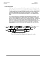

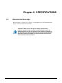
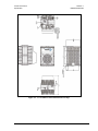
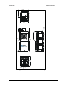
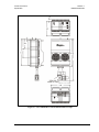
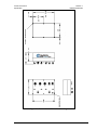

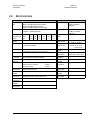
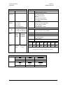
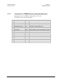


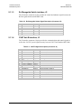
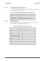


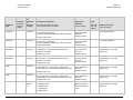

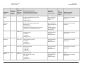
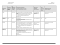
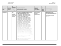
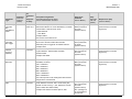


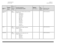
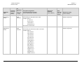
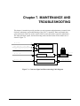
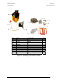
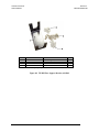
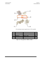


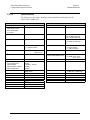

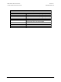
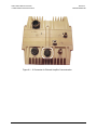

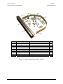

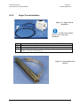
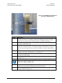

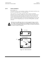
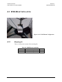
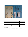
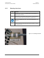
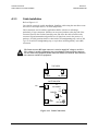
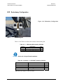
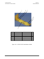
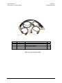
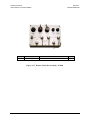
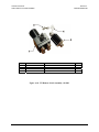
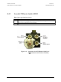
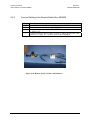
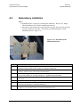

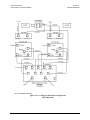

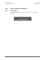

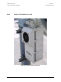
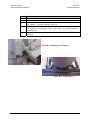


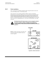

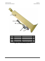

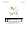

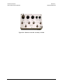
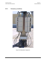


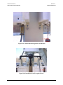

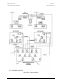

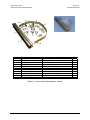
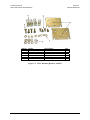

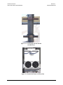

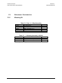
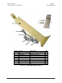
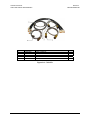


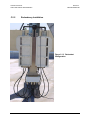
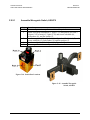
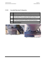
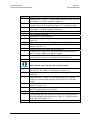
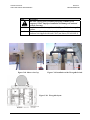

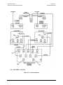


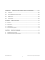


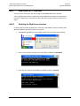
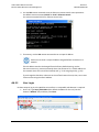
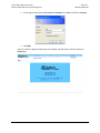
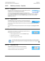
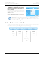

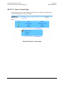
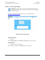
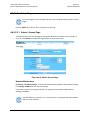

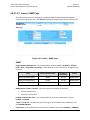

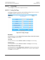
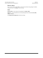
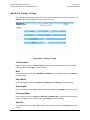
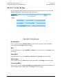
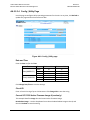

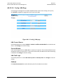


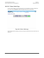

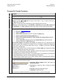

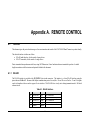
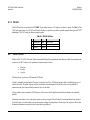
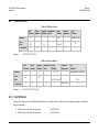
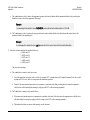

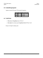
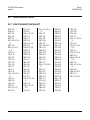
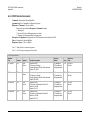

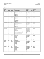

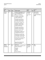
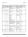


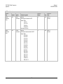
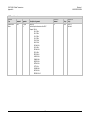
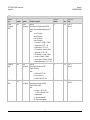
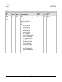
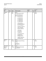

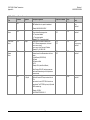
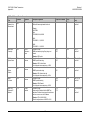
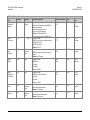
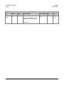
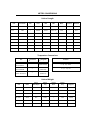


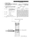
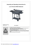

![Installation Manual [PDF 3.2 MB]](http://vs1.manualzilla.com/store/data/006030502_1-1df8339044a93376c13535e606991dae-150x150.png)