1
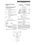
Adding Benchmarking Capabilities to PICML: User Guide
Arvind S. Krishna
[email protected]
Introduction
Platform Independent Component Modeling Language (or PICML, as it will be called hereafter)
is a graphical modeling language for the building blocks of component applications, that is,
applications that are built on top of component middleware. It isn’t intended to represent, or
conform to the specification of, any particular kind of middleware or any particular vendor’s
product. Rather, it’s an environment in which to design and modify component applications in a
way that’s technology-neutral, in a way that can be translated into the middleware flavor of your
choice. One such translator has already been written, and is described in detail at the end of this
document. More are in the works.
PICML itself was designed using the Generic Modeling Environment (GME), a powerful
modeling tool developed at the Institute for Software Integrated Systems (ISIS) at Vanderbilt
University. Models in PICML are also constructed using GME (I told you it was powerful),
since PICML itself can be registered with an installed copy of GME and then selected from a list
of modeling languages when starting a new model project. Documentation, download and other
information can be found on the GME web page at: http://www.isis.vanderbilt.
edu/Projects/gme/
This document pertains to adding benchmarking capabilities to PICML and discusses benchmark generation from higher level models. Using the benchmarking code, metrics such as
roundtrip latency and throughput can be measured. This tool is designed as a helper tool and interacts with other tools such as OCML (Options Configuration Modeling Language) and PICML
(deployment plan evaluation). These tools are a part of a larger tool-suite called Component
Synthesis with Model Integrated Computing CoSMIC. This document does not deal with the
motivation for the development of this capability, rather describes a step-wise process of adding
and composing simple benchmarks using PICML models.
Installing PICML
A Windows installer for PICML is available from the CoSMIC web page listed above. Just
look at the first item under the Downloads header near the top of the page. The benchmarking
capabilities are part of PICML.
Prerequisites
After installing PICML there are two steps that are required before one can set up benchmarks.
These are common to someone building models from scratch of existing PICML models. These
include:
1. Component interactions: Component instances and their ports.
2. Component interfaces: The interfaces provided and required by components.
The BGML generated code uses several capabilities provided by the ACE framework. ACE can
be downloaded from http://deuce.doc.wustl.edu/Download.html. Currently, all
1
generated code from BGML has been tested using the CIAO open-source component middleware framework that runs atop ACE and TAO open-source CORBA middleware. These can be
downloaded from the url provided above.
The first step is provided via ComponentImplementation aspect in PICML. In this view, the
user can drag and drop components and draw the component interactions. For more information
please refer to the user guide exclusively dealing with PICML. The second step is accomplished
via the ComponentTypes aspect in PICML. This aspect deals with specifying the interfaces
of the ports. Please refer to the Interfaced Definitions manual present with the installation of
PICML.
From this point, I assume that the models have both the component interactions and component interfaces. The assumption also includes how to open an existing model, create a new
model (PICML) in GME and some GME terminology. For GME terminology, please refer to
the GME user manual.
BGML Model Elements
This section describes the BGML modeling elements, both their syntax and semantics. For the
purpose of benchmarking, BGML provides the following model elements:
Operation Reference points to a two way IDL operation. The actual operation is
defined in the ComponentTypes aspect of PICML. BGML requires the signature of the
operation to generate benchmarking code
Event Reference points to a CORBA event exchanged between one/many components. Similar to operations, events are also defined in the ComponentTypes aspect of
PICML. The type of event is used by BGML to generate benchmarking code
Latency element is associated with an IDL operation/event. A latency element can
be associated with only one operation or an event. The BGML model interpreter then
uses this association to generate code the measures the latency for each invocation of the
operation/event. For each latency element, the following three attributes to be associated:
1. filename: Generates output a given file, later imported by a graphing tool
2. warmup: number of iterations to warmup before taking the actual benchmark
3. iterations: Number of iterations to compute latency measures
Throughput element similar to Latency is associated with an IDL operation/event.
Every throughput element can be associated with one operation or event. Similar to the
latency measures, the benchmarking code generates the throughput measures. The same
three attributes associated with Latency can also be associated with throughput
Time probe element can be used to generate timing information for both IDL opera2
tions and CORBA events. The start_time_probe() and stop_time_probe()
functions generated from the BGML interpreters can be used to take timestamps before
and after method invocation. These timestamps can then server as input to other timing analysis tools. Every timeprobe element can be associated with many operations and
events.
Benchmarking experiments require some background load either CPU or other requests
during the benchmarking process. These make the results more insightful. A TaskSet is
a set of tasks that can be used to create a certain number of background tasks during the
benchmarking experiment.
A task represents a background activity, in our case generation of requests during the benchmarking process. These requests are remote CORBA operations on the target server process. The number of iterations are the same as the benchmarking operation. Each task set
can be associated with n (1..n) number of background tasks.
Getting Started with BGML
Open PICML model and right click on the RootFolder. This opens up a dialog box. In this box
choose Insert Folder. This should open up a menu with different folders roughly corresponding
to each aspect in PICML. Choose the ComponentAnalyses aspect. This step is illustrated in
Figure 1.
Figure 1: Step 1
Figure 2: Step 2
Step 1 should create a NewComponentAnalyses folder. Right click on this to insert a BenchmarkAnalysis Model. Currently there is only one model or one type of analysis. In future, there
might be different analysis such as one that is specific for MatLab. In that case, there will be
two types, one for Benchmark another for Matlab. This step is shown in Figure 2. Steps 1 & 2
enable creation of a BGML paradigm for modeling benchmarks. After these steps you should
see the screen as shown in Figure 3.
If not, please go over Steps 1 and 2 to see what went wrong. To set up a simple benchmark,
BGML requires the signature of the IDL operation or an Event that has to be benchmarked.
Either of these are to be modeled in the Interface Definitions aspect present in PICML.
3
Figure 3: BGML Paradigm Window
Creating Benchmarking Experiments: A Walk Through
In this section, I describe how to create a benchmarking experiment with PICML. The example
discussed is a part of the RobotAssembly example shipped with the PICML installation present
in: \$COSMIC_ROOT/examples/RobotAssembly.xme. Similar steps can be followed
to create other benchmarks.
In this scenario, a pallet (controlled by a PaletteManager component) containing digital
watches moves to a robot station (controlled by the RobotManager component) where its time
is set using the current time provided by a periodic clock (controlled by a WatchManager).
The management for the watch setting facility located at a remote site can send production
work orders and receive response to orders, ongoing work status, inventory, and other messages.
These instructions are sent to the WatchManager component using ManagementWorkInstructions (MWI) component. The WatchManager component interacts with a human operator who using the HumanMachineInterface (HMI) component accepts/rejects
the watch. When the watch is accepted, the WatchManager component uses the RobotManager component to set the time. When a watch is rejected, however, the RobotManager
component removes the watch from the assembly line. Figure 4 illustrates this assembly of
components.
Figure 4: RobotAssembly Scenario
Figure 5 depicts the interaction between the components in the RobotAssembly scenario using PICML. The details on how to model the scenario in PICML is external to this document.
More details should be available from the PICML documentation guide. As shown in the figure, HumanMachineInterface and WatchSettingManager component interact via a
facet(DisplayResponse) receptacle (HumanResponse) communication.
Figure 6 shows three operations part of the interface exchanged between HumanMachine\
4
Figure 5: RobotAssembly Interaction Scenario
Figure 6: Operations part Facet/Receptacle
Interaction
-Interface and WatchSettingManager components. The relevant IDL is shown below:
interface WorkOrderResponses {
void AcceptWorkOrderResponse(in WorkOrder Order, in StatusType Status);
void SetTimeResponse(in WorkOrder Order, in StatusType Status);
void AcceptFinalProductResponse(in WorkOrder Order, in StatusType Status);
};
NOTE: As stated earlier, modeling components, interfaces and their operations and part of
the PICML documentation and are not explicitly discussed in this document. Please consult the
Interface Definitions documentation and PICML documentation for a detailed description.
At this point, we are ready to create an experiment that measures the roundtrip latency for
the AcceptWorkOrderResponse method. The following is a step wise description:
Step 1: Copy the AcceptWorkOrderResponse operation present in the InterfaceDefinitions aspects of the RobotAssembly model and paste it in the RobotAssembly benchmark
paradigm. Creation of the benchmark paradigm can be done from the first two steps explained
in Getting Started with BGML section. This step is shown in Figure 7.
Figure 7: Copying Operation Signature onto Figure 8: Associating Round-trip Latency with
BGML
Operation
Step 2: Once the operation signature has been copied, associate either Latency or Throughput
metric with this operation. In our case, we drag the latency icon from the palette and drop onto
the pane. Then using the Connect Mode provided by GME, associate the operation with the
Latency Metric. This is done by selecting the source, (operation reference) and the sink (latency
element) one at a time. Figure 8 shows the resulting step.
5
Figure 9: Associating Tasks with TaskSet
Figure 10: Associating Task Set with Latency Metric
Step 3: Select the Latency Metric to configure the attributes, i.e., the number of warmup iterations and number of actual iterations. This can be configured using the attributes.
Step 4: Associate a predetermined number of background tasks with the experiment. To do
this first drag a task set element from the palette. Next, drag and drop the required number of
background tasks using the task element in the palette. Associate each of these tasks with the
task set. For doing this use the Set Mode provided in GME and select the individual tasks to be
part of the task set. This is shown in Figure 9. Next using the Connect Mode connect the latency
metric with the task set.
Checking Constraints. Once this is done. Please check for constraint violations. This can
be done by choosing. File→Check→Check All constraints from the File menu in GME. There
should not be any constraint violations. The final experiment visually should look like what is
shown in Figure 10. If there are any, please see if they pertain to the BGML paradigm and revisit
steps 1-4 to ensure you have followed all the steps. If there are still violations, please export the
GME model via File→Export XML and send the resulting file to [email protected]
If there are no violations you are ready to interpret the file and look at the generated code. This
step is discussed in the next section. Similar steps can be followed for events.
Associating Timer probes: To associate a timer probe connection with either an operation
or an event, follow Step 1 described earlier. Next drag and drop the Timer element and create
a connection between the operation/event with the timer probe. This should be done using the
Connect Mode as described earlier. A single timer atom can be connected to multiple operations
or events. After this association, please follow instructions on how to check constraints via
Checking Constraints section explained earlier.
Generated Code: A Walk Through
Having built the models, the next step is to invoke the interpreter to generate the required benchmarking code. There are several interpreters in GME, one can look at all the interpreters by
clicking the i icon present in the GME toolbar. Alternatively, one can directly invoke the BGML
interpreter by choosing the BGML interpreter icon as shown in Figure 3. All the generated code
from BGML uses several classes provided by the ACE framework including, Barriers, Threads,
and priority mechanisms. The use of ACE ensures that the generated code from BGML can
be run across different platforms and compilers. ACE is freely available and can be downloaded from http://deuce.doc.wustl.edu/Download.html. This also means that
currently BGML generates C++ code. We do plan to generate java benchmarking code as well.
If you are interested or need this functionality please email me at [email protected].
Next a description of the generated code is provided.
6
Benchmark Header & Source Files
The interpreter generates header and source files that have “Benchmark” followed by “Operation
Name” as their names. For the examples the files generated include Benchmark AcceptWorkOrderResponse.{h/cpp}. Below we show the structure of the generated code. This is done as it is
important in our case to understand what the actual benchmarking code looks like.
Header File
1:#ifndef BENCHMARK_ACCEPTWORKORDERRESPONSE_H
2: #define BENCHMARK_ACCEPTWORKORDERRESPONSE_H
3: #include "BGML_Task_Base.h"
4: #include "HumanMachineInterface_exec.h"
5: #include "Benchmark_AcceptWorkOrderResponse_export.h"
6: template <typename T>
7: BENCHMARK_ACCEPTWORKORDERRESPONSE_Export class
8: Benchmark_AcceptWorkOrderResponse : public BGML_Task_Base
9: {
10: public:
11:
Benchmark_AcceptWorkOrderResponse (T* remote_ref,
12:
const RobotAssembly::WorkOrder& arg0,
13:
RobotAssembly::StatusType arg1);
14:
15:
˜Benchmark_AcceptWorkOrderResponse ();
int svc (void);
16: protected:
17:
T* remote_ref_;
18:
const RobotAssembly::WorkOrder & arg0_;
19:
RobotAssembly::StatusType arg1_;
20: };
#include "Benchmark_AcceptWorkOrderResponse.cpp"
#endif // BENCHMARK_ACCEPTWORKORDERRESPONSE_H
Lines 3–5 illustrate the include files required. All the benchmarking classes inherit from
BGML_Task_Base class. This class inherits from ACE_Task_Base which enables the
Benchmark class to be associated with a thread. The Human_MachineInterface_exec.
h declares the signature for operation to be benchmarked. Lines 6–8 illustrate the class definition. The class itself is generic and requires a type T. This type corresponds to the type of the
remote interface. Lines 10 – 13 describes the constructor. The constructor take in three arguments, each corresponding to the arguments required by the remote operations. In our case the
operation signature was: AcceptWorkOrderResponse(in WorkOrder Order, in
StatusType Status); The signature of the operation corresponds to the CORBA mapping of IDL operation. The T* remote ref is a pointer to the remote interface on which the
operation will be invoked. The svc () method shown in Line 15 is the actual function in
which the benchmarking is done. This function also serves as the entry point for a thread associated with the benchmarking class.
Benchmarking source file
#ifndef BENCHMARK_ACCEPTWORKORDERRESPONSE_C
#define BENCHMARK_ACCEPTWORKORDERRESPONSE_C
#include "Benchmark_AcceptWorkOrderResponse.h"
#include "ace/High_Res_Timer.h"
#include "ace/Stats.h"
7
#include "ace/Sample_History.h"
#include "AcceptWorkOrderResponse_Workload.h"
template <typename T>
int
Benchmark_AcceptWorkOrderResponse<T>::svc (void)
{
for (int warm_up = 0; warm_up < 100; warm_up++)
(void) this->remote_ref_->
AcceptWorkOrderResponse (arg0_,arg1_ ACE_ENV_ARG_PARAMETER);
ACE_Barrier barrier (3);
// Generate the Background workload
AcceptWorkOrderResponse_Workload<T> task0 (remote_ref_, arg0_, arg1_, barrier);
AcceptWorkOrderResponse_Workload<T> task1 (remote_ref_, arg0_, arg1_, barrier);
AcceptWorkOrderResponse_Workload<T> task2 (remote_ref_, arg0_, arg1_, barrier);
// Activate the Background tasks
if (task0.activate (THR_NEW_LWP | THR_JOINABLE, 1,
ACE_ERROR ((LM_ERROR, "Error activating workload
if (task1.activate (THR_NEW_LWP | THR_JOINABLE, 1,
ACE_ERROR ((LM_ERROR, "Error activating workload
if (task2.activate (THR_NEW_LWP | THR_JOINABLE, 1,
ACE_ERROR ((LM_ERROR, "Error activating workload
1) ==
task0
1) ==
task1
1) ==
task2
-1)
\n"));
-1)
\n"));
-1)
\n"));
ACE_Sample_History history (5000);
ACE_hrtime_t test_start = ACE_OS::gethrtime ();
ACE_UINT32 gsf = ACE_High_Res_Timer::global_scale_factor ();
for (int i = 0; i < 5000; i++)
{
ACE_hrtime_t start = ACE_OS::gethrtime ();
(void)this->remote_ref_->
AcceptWorkOrderResponse (arg0_,arg1_ ACE_ENV_ARG_PARAMETER);
ACE_CHECK;
ACE_hrtime_t now = ACE_OS::gethrtime ();
history.sample (now - start);
}
ACE_hrtime_t test_end = ACE_OS::gethrtime ();
ACE_DEBUG ((LM_DEBUG, "test finished"));
ACE_DEBUG ((LM_DEBUG, "High resolution timer calibration...."));
ACE_DEBUG ((LM_DEBUG, "done"));
ACE_Basic_Stats stats;
history.collect_basic_stats (stats);
stats.dump_results ("Total", gsf);
ACE_Throughput_Stats::dump_throughput ("Total",
gsf,
test_end - test_start,
stats.samples_count ());
return 1;
}
#endif // BENCHMARK_ACCEPTWORKORDERRESPONSE_H
As illustrated in the code snippet, the svc() method first warms up the system by invoking
the required number of warmup iterations. Based on the number of background tasks modeled,
in our case 3, the interpreter generates three AcceptWorkOrderResponse_Workload
background tasks each of which send requests concurrently when the actual benchmarking operation is done. The next step activates each of these tasks. Once the background tasks are
activated, the actual benchmarking code to measure the round trip latency is generated. Finally,
8
after computing the results, the statistics are displayed.
Build file
The model interpreter also generates a build file to compile the generated benchmark code and
create a shared library that can be linked to the actual application that requires this functionality.
The build files use MPC (Make Project Creator) which generates the required Makefiles or
Visual C++ build files. MPC is available for download from OCI via http://www.ociweb.
com/product/mpc/. We provide the build file for sake of completeness. The next section
describes how one can build and run the benchmarks.
project (Benchmark_AcceptWorkOrderResponse) : acelib , ciao_client {
includes += $(BGML_HOME)
libs
+= BGML_Base
libpaths += $(BGML_HOME)
Source_Files {
AcceptWorkOrderResponse_Workload.cpp
Benchmark_AcceptWorkOrderResponse.cpp
}
}
Running Benchmarks Generated from BGML
In this section I describe how the benchmarking files generated from BGML can be run. These
examples were tested on the DAnce open-source component middleware. To compile the benchmarks first one needs to compile the BGML Base directory shipped with PICML installation.
Move the sources to a directory for example:
build/arvindk/software/BGML Base. Next set up an environment variable $BGML HOME that
points to this directory. Next run the mwc.pl (MakeProjectCreator) file shipped with MPC to
generate the build file. After which compile the directory using the appropriate make command.
Below we show the compilation snippet using gmake on Linux platform.
bash-2.05$ /build/arvindk/ACE_wrappers/bin/mwc.pl
Generating gnuace output using default input
Start Time: Fri Nov 19 11:42:53 2004
End Time: Fri Nov 19 11:42:53 2004
bash-2.05b$ make
make[1]: Entering directory ‘/build/arvindk/CoSMIC/PIM/PICML/interpreters/BGML_Base’
GNUmakefile:
/build/arvindk/CoSMIC/PIM/PICML/interpreters/BGML_Base/GNUmakefile.BGML_Base
MAKEFLAGS=w
g++ -W -Wall -Wpointer-arith -O3 -g -pipe -D_REENTRANT
-DACE_HAS_AIO_CALLS -D_GNU_SOURCE -I/build/arvindk/ACE_wrappers
-DACE_HAS_EXCEPTIONS -D__ACE_INLINE__ -I/build/arvindk/ACE_wrappers
-DBGML_BASE_BUILD_DLL -c -fPIC -o .shobj/BGML_Task_Base.o
BGML_Task_Base.cpp
g++ -D_REENTRANT -DACE_HAS_AIO_CALLS -D_GNU_SOURCE
-I/build/arvindk/ACE_wrappers -DACE_HAS_EXCEPTIONS -D__ACE_INLINE__
-I/build/arvindk/ACE_wrappers -DBGML_BASE_BUILD_DLL -shared -Wl,-h
-Wl,libBGML_Base.so.5.4.2 -o libBGML_Base.so.5.4.2
.shobj/BGML_Task_Base.o -Wl,-E -L/build/arvindk/ACE_wrappers/ace -L./
-L/build/arvindk/ACE_wrappers/lib -lACE -ldl -lpthread -lrt rm -f
libBGML_Base.so ln -s libBGML_Base.so.5.4.2 libBGML_Base.so chmod a+rx
libBGML_Base.so.5.4.2 Installing libBGML_Base.so ->
/build/arvindk/ACE_wrappers/lib Installing libBGML_Base.so.5.4.2 ->
/build/arvindk/ACE_wrappers/lib make[1]: Leaving directory
‘/build/arvindk/CoSMIC/PIM/PICML/interpreters/BGML_Base’
9
Next compile the benchmarking files. Copy the generated files to the appropriate directory.
In particular to the one where the “HumaManchineInterface” component is located. Follow similar steps as describe earlier. Compilation generates libBenchmark AcceptWorkOrderResponse.so
library on a linux platform.
The final step is to invoke the benchmarking code from within the component implementation to begin the benchmark. In particular, the following lines of code should be added to the
implementation:
RobotAssembly::WorkOrderResponses_var rev = this->context_->
get_connection_HumanResponse (ACE_ENV_SINGLE_ARG_PARAMETER);
ACE_CHECK;
if (CORBA::is_nil (rev.in ()))
ACE_THROW (CORBA::BAD_INV_ORDER ());
Benchmark_AcceptWorkOrderResponse<RobotAssembly::WorkOrderResponses>
benchmark (rev.in (), myOrder, myStatus);
if (benchmark.activate (THR_NEW_LWP|THR_JOINABLE, 1, 1) == -1)
ACE_ERROR ((LM_ERROR, "Error activating workload task0 \n"));
The first two lines shows how the remote reference to the interface can be obtained via the
provided facet. The next two lines show the creation of a benchmarking task and passing in
the required parameters (myOrder and myStatus) which are defined earlier. Final step involves
activation of task which also starts the benchmarking experiment. After adding this code, the
user must link the application with libBenchmark AcceptWorkOrderResponse.so library.
If there are any errors in the generated code, i.e., runtime or compilation errors please report
them to [email protected]
Planned Feature Additions
The following are some planned future additions:
1. Generate Java benchmarking code. This will be tailored towards OpenCCM implementation.
2. Currently, all tasks are continuous i.e., invoke operations at the fastest possible rate. The
future enhancement is to generate tasks that invoke operations at a given rate or priority.
3. Integrate this tool with other CPU workload generators such as Hourglass and CPU Broker. Please see the following URL for more information: http://www.cs.utah.
edu/˜regehr/hourglass/.
Summary
This document dealt with modeling and generation of benchmarking experiments using BGML.
This tool automates the manual task of generating benchmarks from models with very less
overhead. The generated code and the build files can be used to compile the files on multiple
platforms with no user modifications. We have used the tool to quickly evaluate the performance
of systems for a given configuration. The configuration information generated from the OCML
tool (part of the CoSMIC tool chain). Similarly the tool can also be used to evaluate the deployment plan, i.e., how components map on to target nodes. Any feedback, suggestion or criticism
please direct to Arvind S. Krishna [email protected].
10