1
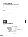
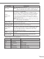
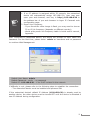
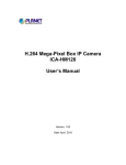
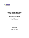
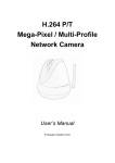
2 Mega-Pixel IR Outdoor PoE IP Camera
ICA-HM351 / ICA-HM312
Quick Installation Guide
Table of Contents
Chapter 1. Introduction..................................................................................... 3
1.1 Before Installation................................................................................ 3
1.2 System Requirements........................................................................... 3
Chapter 2. Physical Description and Installation................................................... 4
2.1 ICA-HM351 2 Mega-Pixel 35M IR Outdoor Box PoE IP Camera.................. 4
2.1.1 ICA-HM351 Package Content........................................................ 4
2.1.2 ICA-HM351 Physical Details.......................................................... 4
2.1.3 ICA-HM351 Installation................................................................ 6
2.2 ICA-HM312 2 Mega-Pixel 25M IR Outdoor Bullet PoE IP Camera............... 6
2.2.1 ICA-HM312 Package Content........................................................ 6
2.2.2 ICA-HM312 Physical Details.......................................................... 6
2.2.3 ICA-HM312 Installation................................................................ 8
Chapter 3. Camera Windows Utility.................................................................... 9
Further Information.........................................................................................12
Chapter 1. Introduction
Thank you for purchasing the PLANET 2 Mega-Pixel H.264 IR Outdoor PoE IP
Camera. It is versatile and high image solution of surveillance application for
day and night. The PLANET IP Camera support Multi-Profile function can stands
for simultaneously video streams. These Network Cameras can generate H.264,
MPEG-4 and M-JPEG streaming simultaneously to different clients. Moreover, the
resolution can be different from one client to another. This state-of-art design is
considerable to fit in various network environments.
1.1 Before Installation
Before installation, please be sure to read this quick installation guide and user’s
manual (CD) carefully to complete machine installation. This guide shows how to
quick set up the three cameras, unless model name specified terms “IP Camera”
will be used for these three models.
1.2 System Requirements
CPU
Intel Dual Core 2.0GHz or higher
RAM
2GB (above Recommended)
Video RAM
128MB (above Recommended)
Display Resolution
1024 x 768 24bits or above
Operating System
Windows XP / Vista / Win7
DirectX
10 or above
Network
Wired Ethernet 100Base-TX
3
Chapter 2. Physical Description and Installation
2.1 ICA-HM351 2 Mega-Pixel 35M IR Outdoor Box PoE IP Camera
2.1.1 ICA-HM351 Package Content
ICA-HM351 x 1
Power Adapter x 2
Wall Mounting Kit x 1
User’s Manual CD x 1
Quick Installation Guide x 1
Note
If any of the above items are missing, please contact your dealer
immediately.
2.1.2 ICA-HM351 Physical Details
ICA-HM351 Connector
DI/DO, RS-485
Video out (BNC)
Microphone Input
Audio Output
DC Power
(IR and IP Camera)
RJ-45
(PoE, IR and IP Camera)
Reset
DC Power
(Fan and Heater)
4
Interface
Description
DC Power
(Power Jack, IR
and IP Camera)
The input power is DC 12V, 1A.
Note: ONLY use package power adapter supplied with the
internet. Otherwise, the product may be damaged.
RJ-45
(LAN socket,
PoE, IR and IP
Camera )
Connect to PC or Hub/Switch.
For connect to 10Base-T Ethernet or 100Base-TX Fast
Ethernet cabling. This Ethernet port built auto-negotiation
protocol can detect or negotiate the transmission speed
of the network automatically. Please use CAT-5 cable to
connect the Network Camera to a 100Mbps Fast Ethernet
network switch or hub.
Note: ONLY use one power source, either from DC or from
802.3af Power over Ethernet.
Audio Output
(Green, Line Out)
Connect a loud speaker to the IP Camera. This is for voice
alerting and two-way audio.
Microphone Input
(Pink, Audio In)
Connect a microphone to the IP Camera.
Video Output
(BNC)
The Network Camera also provides composite video output.
The video output function is only for easy installation to
check view angle and focus. Furthermore, only “720p
Mode” supports this function.
Reset
(Factory Default)
This button is used to restore the all factory default
settings.
DI/DO, RS-485
The 6 pin terminal block includes 1 input ports and 1
output ports, and RS-485 D+ and D-.
DC Power
(Power Jack, Fan
and Heater)
The input power is DC 12V, 1A for Fan and Heater.
Terminal block for I/O connectors:
Name
Cable Color
Function
12VDC
Brown/White
DC 12V (50mA maximum)
GND
Blue/White
GND
D+
Purple/White
RS485 data +
D-
Gray
RS485 data -
DI
Green/White
Digital signal input
DO
Orange/White
Digital signal output
5
2.1.3 ICA-HM351 Installation
1.Fix IR camera to desired location with wall mount fixture
2.Plug-in Ethernet Cable into RJ-45 connector
Connect an Ethernet cable to the LAN socket located on the Network Camera’s
back panel and attach it to the network.
3.Connect RS485 D+ and D- (if you need to control PT scanner)
4.Connect the attached power adapters to camera and heater (option/by model)
and plug-in these adapters into power outlet
5.Done
2.2 ICA-HM312 2 Mega-Pixel 25M IR Outdoor Bullet PoE IP Camera
2.2.1 ICA-HM312 Package Content
ICA-HM312 x 1
Power Adapter x 1
Camera Mount Kit x 1
User’s Manual CD x 1
Quick Installation Guide x 1
Note
If any of the above items are missing, please contact your dealer
immediately.
2.2.2 ICA-HM312 Physical Details
ICA-HM312 Connector
DI/DO, RS-485
Video Output (BNC)
Microphone Input
Audio Output
DC Power
RJ-45 (PoE)
Reset
6
Interface
Description
DC Power
The input power is DC 12V, 1A.
Note: ONLY use package power adapter supplied with the
internet. Otherwise, the product may be damaged.
RJ-45
(LAN socket,
PoE )
Connect to PC or Hub/Switch.
For connect to 10Base-T Ethernet or 100Base-TX Fast
Ethernet cabling. This Ethernet port built auto-negotiation
protocol can detect or negotiate the transmission speed
of the network automatically. Please use CAT-5 cable to
connect the Network Camera to a 100Mbps Fast Ethernet
network switch or hub.
Note: ONLY use one power source, either from DC or from
802.3af Power over Ethernet.
Audio Output
(Green, Line Out)
Connect a loud speaker to the IP Camera. This is for voice
alerting and two-way audio.
Microphone Input
(Pink, Audio In)
Connect a microphone to the IP Camera.
Video Output
(BNC)
The Network Camera also provides composite video output.
The video output function is only for easy installation to
check view angle and focus. Furthermore, only “720p
Mode” supports this function.
Reset
(Factory Default)
This button is used to restore the all factory default
settings.
DI/DO, RS-485
The 6 pin terminal block includes 1 input ports and 1
output ports, and RS-485 D+ and D-.
Terminal block for I/O connectors:
Name
Cable Color
Function
12VDC
Brown/White
DC 12V (50mA maximum)
GND
Blue/White
GND
D+
Purple/White
RS485 data +
D-
Gray
RS485 data -
DI
Green/White
Digital signal input
DO
Orange/White
Digital signal output
7
2.2.3 ICA-HM312 Installation
1.Fix IR camera to desired location with wall mount fixture
2.Plug-in Ethernet Cable into RJ-45 connector
Connect an Ethernet cable to the LAN socket located on the Network Camera’s
back panel and attach it to the network.
3.Connect RS485 D+ and D- (if you need to control PT scanner)
4.Connect the attached power adapters to camera and heater (option/by model)
and plug-in these adapters into power outlet
5.Done
8
Chapter 3. Camera Windows Utility
This chapter shows how to quick set up your 2 Mega-Pixel H.264 IR Outdoor PoE
IP Camera. The 2 Mega-Pixel H.264 IR Outdoor PoE IP Camera is with the default
settings. However to help you find the networked camera quickly the windows
utility (PLANET IPWizard II) can search the IP cameras in the network that shall
help you to configure some basic setting before you started advanced management
and monitoring.
Please insert the bundle CD disk into your CD/DVD-ROM drive. When the welcome
web page appears, please click your IP camera name on the IP camera list. Then
click the PLANET IPWizard II hyperlink to start the PLANET IPWizard II.
Search function:
Press “Search” button. PLANET IPWizard II will list all networked devices in the
LAN. If the IP camera doesn’t be found, you may check this IP camera is connect
to network properly and press the search button again.
9
View function:
If PLANET IPWizard II finds network devices, View button will be available. Please
select the device you want to view and click the View button. Furthermore you
could double click the left button of mouse to link to the network device by
browser.
LAN setting:
The utility featured with “LAN” setting function to help user to modify the IP
parameters of the installed network devices. User can step by step to setup IP
address, username and password.
10
Note
1. If no IP address is assigned within 30 seconds, the networked
device will automatically assign 192.168.0.20. User may now
open your web browser, and key in http://192.168.0.20 in
the address bar of you web browser to logon IP Camera’s web
configuration page.
2. Power Line Frequency
- If you found the video image is flash, you may need to choose
50 or 60 Hz frequency (depends on different country).
- World wide power line frequency table is inside user’s manual,
Appendix.
After connected to networked device, the device will prompt for User name and
Password. For the first time, please enter: admin as username and no password
to continue Web Management.
Default User Name: admin
Default Password: <null> - no password
Default IP: 192.168.0.20 – if no DHCP existed in the network
If difficulty is met, please refer to the following steps to establish the connection:
- The networked device must be installed and powered ON.
If the networked device’s default IP Address (192.168.0.20) is already used by
another device, the other device must be turned OFF until the device is allocated a
new IP Address during configuration.
11
Further Information
This guide is used to help you startup your IP Camera settings. It is also
recommended to check the user manual in CD disk for more details of the system
and user configuration.
12