1
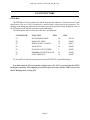
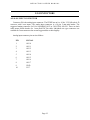
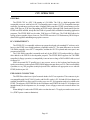
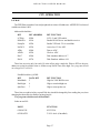
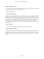
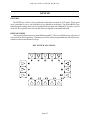
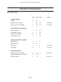
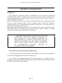
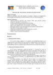
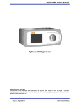
FPWX USER'S MANUAL
V1.6
Copyright 1997 by MESA ELECTRONICS Richmond, CA. Printed in the United States of America.
All rights reserved. This document and the data disclosed herein is not to be reproduced, used,
disclosed in whole or in part to anyone without the written permission of MESA ELECTRONICS.
Mesa Electronics
4175 Lakeside Drive, Suite #100
Richmond, CA 94806-1950
Tel (510) 223-9272 - Fax (510) 223-9585
E-Mail: [email protected] - Website: www.mesanet.com
TABLE OF CONTENTS
GENERAL
DESCRIPTION . . . . . . . . . . . . . . . . . . . . . . . . . . . . . . . . . . . . . . . . . . . . . . . . . . . . . . . . . . . . . . . . . . . . . . . . . . . . . 5
WARNINGS
WARNINGS . . . . . . . . . . . . . . . . . . . . . . . . . . . . . . . . . . . . . . . . . . . . . . . . . . . . . . . . . . . . . . . . . . . . . . . . . . . . . . . . 6
HARDWARE CONFIGURATION
GENERAL . . . . . . . . . . . . . . . . . . . . . . . . . . . . . . . . . . . . . . . . . . . . . . . . . . . . . . . . . . . . . . . . . . . . . . . . . . . . . . . . . . 7
INSTALLING AND REMOVING DISK CHIPS . . . . . . . . . . . . . . . . . . . . . . . . . . . . . . . . . . . . . . . . . . . 7
I/O CONNECTORS
GENERAL . . . . . . . . . . . . . . . . . . . . . . . . . . . . . . . . . . . . . . . . . . . . . . . . . . . . . . . . . . . . . . . . . . . . . . . . . . . . . . . . . . 8
FPWX CONNECTOR AND CHIP LOCATIONS . . . . . . . . . . . . . . . . . . . . . . . . . . . . . . . . . . . . . . . . . . . 9
SERIAL INTERFACE AND POWER CONNECTOR . . . . . . . . . . . . . . . . . . . . . . . . . . . . . . . . . . . . . 10
PARALLEL PORT CONNECTOR . . . . . . . . . . . . . . . . . . . . . . . . . . . . . . . . . . . . . . . . . . . . . . . . . . . . . . . . 11
ANALOG INPUT CONNECTOR . . . . . . . . . . . . . . . . . . . . . . . . . . . . . . . . . . . . . . . . . . . . . . . . . . . . . . . . . . 12
DISK EMULATOR OPERATION
GENERAL . . . . . . . . . . . . . . . . . . . . . . . . . . . . . . . . . . . . . . . . . . . . . . . . . . . . . . . . . . . . . . . . . . . . . . . . . . . . . . . . . 13
STARTUP . . . . . . . . . . . . . . . . . . . . . . . . . . . . . . . . . . . . . . . . . . . . . . . . . . . . . . . . . . . . . . . . . . . . . . . . . . . . . . . . . . 13
BYPASSING THE DISK EMULATOR . . . . . . . . . . . . . . . . . . . . . . . . . . . . . . . . . . . . . . . . . . . . . . . . . . . 13
RELIABILITY . . . . . . . . . . . . . . . . . . . . . . . . . . . . . . . . . . . . . . . . . . . . . . . . . . . . . . . . . . . . . . . . . . . . . . . . . . . . . 14
DISK EMULATOR INITIALIZATION . . . . . . . . . . . . . . . . . . . . . . . . . . . . . . . . . . . . . . . . . . . . . . . . . . . 14
CPU OPERATION
GENERAL . . . . . . . . . . . . . . . . . . . . . . . . . . . . . . . . . . . . . . . . . . . . . . . . . . . . . . . . . . . . . . . . . . . . . . . . . . . . . . . . . 16
PC COMPATIBILITY . . . . . . . . . . . . . . . . . . . . . . . . . . . . . . . . . . . . . . . . . . . . . . . . . . . . . . . . . . . . . . . . . . . . . 16
EXPANSION BUS CONNECTOR . . . . . . . . . . . . . . . . . . . . . . . . . . . . . . . . . . . . . . . . . . . . . . . . . . . . . . . . 14
I/O MAP . . . . . . . . . . . . . . . . . . . . . . . . . . . . . . . . . . . . . . . . . . . . . . . . . . . . . . . . . . . . . . . . . . . . . . . . . . . . . . . . . . . . 17
HARDWARE TIC CLOCK . . . . . . . . . . . . . . . . . . . . . . . . . . . . . . . . . . . . . . . . . . . . . . . . . . . . . . . . . . . . . . . . 18
SERIAL PORT . . . . . . . . . . . . . . . . . . . . . . . . . . . . . . . . . . . . . . . . . . . . . . . . . . . . . . . . . . . . . . . . . . . . . . . . . . . . . 18
RS-232 / RS485 OPERATION . . . . . . . . . . . . . . . . . . . . . . . . . . . . . . . . . . . . . . . . . . . . . . . . . . . . . . . . . . . . . 18
SERIAL FILE DOWNLOAD . . . . . . . . . . . . . . . . . . . . . . . . . . . . . . . . . . . . . . . . . . . . . . . . . . . . . . . . . . . . . . 19
TABLE OF CONTENTS
CPU OPERATION
A-D CONVERTER . . . . . . . . . . . . . . . . . . . . . . . . . . . . . . . . . . . . . . . . . . . . . . . . . . . . . . . . . . . . . . . . . . . . . . . . 21
PARALLEL PORT . . . . . . . . . . . . . . . . . . . . . . . . . . . . . . . . . . . . . . . . . . . . . . . . . . . . . . . . . . . . . . . . . . . . . . . . . 22
CONSOLE SWITCHING . . . . . . . . . . . . . . . . . . . . . . . . . . . . . . . . . . . . . . . . . . . . . . . . . . . . . . . . . . . . . . . . . . 22
EXTENDED INT 1A FUNCTIONS. . . . . . . . . . . . . . . . . . . . . . . . . . . . . . . . . . . . . . . . . . . . . . . . . . . . . . . . 22
SETUP STORAGE . . . . . . . . . . . . . . . . . . . . . . . . . . . . . . . . . . . . . . . . . . . . . . . . . . . . . . . . . . . . . . . . . . . . . . . . . 24
DISPLAY
GENERAL . . . . . . . . . . . . . . . . . . . . . . . . . . . . . . . . . . . . . . . . . . . . . . . . . . . . . . . . . . . . . . . . . . . . . . . . . . . . . . . . . 25
SYSTEM RESOURCES USED . . . . . . . . . . . . . . . . . . . . . . . . . . . . . . . . . . . . . . . . . . . . . . . . . . . . . . . . . . . . 25
TEXT MODE . . . . . . . . . . . . . . . . . . . . . . . . . . . . . . . . . . . . . . . . . . . . . . . . . . . . . . . . . . . . . . . . . . . . . . . . . . . . . . 25
TEXT FONTS . . . . . . . . . . . . . . . . . . . . . . . . . . . . . . . . . . . . . . . . . . . . . . . . . . . . . . . . . . . . . . . . . . . . . . . . . . . . . . 26
TEXT WINDOW . . . . . . . . . . . . . . . . . . . . . . . . . . . . . . . . . . . . . . . . . . . . . . . . . . . . . . . . . . . . . . . . . . . . . . . . . . . 26
GRAPHICS . . . . . . . . . . . . . . . . . . . . . . . . . . . . . . . . . . . . . . . . . . . . . . . . . . . . . . . . . . . . . . . . . . . . . . . . . . . . . . . . 26
EXTENDED INT 10 FUNCTIONS . . . . . . . . . . . . . . . . . . . . . . . . . . . . . . . . . . . . . . . . . . . . . . . . . . . . . . . . 27
CONTRAST ADJUST . . . . . . . . . . . . . . . . . . . . . . . . . . . . . . . . . . . . . . . . . . . . . . . . . . . . . . . . . . . . . . . . . . . . . 32
DEMO PROGRAMS . . . . . . . . . . . . . . . . . . . . . . . . . . . . . . . . . . . . . . . . . . . . . . . . . . . . . . . . . . . . . . . . . . . . . . . 32
PCX2HEX . . . . . . . . . . . . . . . . . . . . . . . . . . . . . . . . . . . . . . . . . . . . . . . . . . . . . . . . . . . . . . . . . . . . . . . . . . . . . . . . . . 33
MINT . . . . . . . . . . . . . . . . . . . . . . . . . . . . . . . . . . . . . . . . . . . . . . . . . . . . . . . . . . . . . . . . . . . . . . . . . . . . . . . . . . . . . . . 34
KEYPAD
GENERAL . . . . . . . . . . . . . . . . . . . . . . . . . . . . . . . . . . . . . . . . . . . . . . . . . . . . . . . . . . . . . . . . . . . . . . . . . . . . . . . . . 35
KEY LOCATIONS . . . . . . . . . . . . . . . . . . . . . . . . . . . . . . . . . . . . . . . . . . . . . . . . . . . . . . . . . . . . . . . . . . . . . . . . . 35
KEYPAD CODES . . . . . . . . . . . . . . . . . . . . . . . . . . . . . . . . . . . . . . . . . . . . . . . . . . . . . . . . . . . . . . . . . . . . . . . . . . 36
REFERENCE INFORMATION
SPECIFICATIONS . . . . . . . . . . . . . . . . . . . . . . . . . . . . . . . . . . . . . . . . . . . . . . . . . . . . . . . . . . . . . . . . . . . . . . . . 37
WARRANTY . . . . . . . . . . . . . . . . . . . . . . . . . . . . . . . . . . . . . . . . . . . . . . . . . . . . . . . . . . . . . . . . . . . . . . . . . . . . . . 38
SCHEMATIC DIAGRAMS . . . . . . . . . . . . . . . . . . . . . . . . . . . . . . . . . . . . . . . . . . . . . . . . . . . . . . . . . . . . . . . . 39
MESA FPWX USERS MANUAL
GENERAL
DESCRIPTION
The FPWX is a tiny PC compatible CPU with integrated LCD graphic display and a thin, flat form
factor (2.6"H x 4.5"W x 1.0"D). The FPWX is a complete OEM embedded system user interface CPU
with display, keyboard, serial and parallel I/O, flash disk, and power supply.
Since the FPWX is PC compatible, most standard PC development tools and languages can be
used for application programming. The FPWX has ROM-DOS pre-installed in its BIOS EPROM,
and needs only your application program to make a complete user interface.
The FPWX display is a 128 by 64 resolution monochrome, graphic, backlit or reflective LCD.
Display dot pitch is .52 mm. Text display modes include a 16 character by 4 line mode (8X14
character cell) and a 21 character by 8 line mode (6X8 character cell). Graphics are handled directly by
the FPWX BIOS (drawdot, drawline, and bitblt.) A BGI graphics driver is supplied to support
Borland compilers. Blinking graphics and 3 level gray scale are possible by using multiple frame
buffers. FPWX display contrast can be adjusted via built-in software commands. The optional EL
backlight can be turned on and off under software control. The keyswitch array surrounds the display
area so that the keys can be labeled in the display. Each key can return a user selectable scan code. The
FPWX BIOS provides support for soft-key graphic and text labels.
The FPWX requires only +5V power for operation, since display and RS-232 interface power are
generated on card. The low operating power and small size of the FPWX make it well suited to
portable applications. Maximum operating current is 160 mA. with backlight off. FPWX Power can
be reduced to approximately 50 mA. by halting the CPU.
The FPWX CPU is a 9.2 MHz PC compatible processor (NEC V40) with 128K or 512K of system
RAM, a 128K or 256K BIOS EPROM, and a socket for one 128 to 512K byte disk emulator EPROM
or flash EEPROM. The on card flash disk is supported by the FPWX BIOS, and appears to the system
as a standard hard disk. A MESA provided file download utility is included in the FPWX BIOS. This
allows you to down load your application program to the FPWX's disk emulator from any PC with a
serial port. All utilities for using the flash disk are provided with the FPWX.
On card I/O includes a RS-232 / RS-485 serial port capable of up to 115K baud, 16 bits of parallel
I/O (2/3 82C55), an eight input, 8 bit (optionally 10 bit) A-D converter, and an optional battery
backed clock calendar.
A 64 pin XT bus pin-out compatible header is provided for user expansion. Adaptors to ISA bus
cards and PC104 cards are available from MESA. A form factor compatible system support card is
available as an option. This card, the FPWX-SSB, has a 1.44M floppy controller, 2 RS-232 serial
ports, and a parallel printer port.
Page 5
MESA FPWX USERS MANUAL
WARNINGS
The FPWX display has dangerous voltages present when the
backlight is operating. Do not touch the back or sides of the display
when power is applied to the FPWX.
The FPWX uses a Lithium cell which can create a fire or
explosion hazard if improperly handled. Do not expose the Lithium
cell to temperatures in excess of 100oC, or dispose of in fire. Do not
attempt to charge the Lithium cell or modify the circuitry
associated with the Lithium cell. Do not short circuit the Lithium
cell (Be careful not to set the FPWX CPU card on to a conductive
surface).
The FPWX display uses high voltages on necessarily closely spaced components and traces. To
avoid electrical problems, conductive debris, dust, metal shavings etc. must be kept away from the
display electronics. For the same reason, do not operate the FPWX where condensation is possible.
If the FPWX is brought from a cold environment to a warmer one such that condensation occurs,
always allow the FPWX to dry thoroughly before applying power.
The FPWX electronics can be damaged by static charge. The FPWX should be removed from it's
protective packing only at a static free workstation.
Page 6
MESA FPWX USERS MANUAL
HARDWARE CONFIGURATION
GENERAL
When performing any hardware setup (including changing memory chips and installing cables) on
the FPWX, power must be OFF! The FPWX can be damaged by plugging in the power cable or
changing chips when power is on. In addition, hazardous voltages exist on the FPWX when the
backlight is on. As the display is fragile, it is suggested that all configuration be done with the display
face down on a soft pad.
Chip and connector locations discussed in this manual assume that the FPWX is oriented display
down, with the expansion bus connector (the large 64 pin header) on the left hand side.
INSTALLING AND REMOVING DISK CHIPS
The disk emulator chip on the FPWX is in socket U2. Disk emulator chips may be installed by
1: Orienting the pin 1 dimple of the chip in the up position.
2: Setting the chip in socket U2, making sure that the socket fingers are aligned with the
chip pins.
3: Gently pressing the chip into the socket
To remove a disk emulator chip, you must have access to a 32 pin PLCC chip puller. Bent paper
clips or other improvised tools may damage the socket and void the FPWX warranty.
Page 7
MESA FPWX USERS MANUAL
I/O CONNECTORS
GENERAL
The FPWX has 3 user I/O connectors, and an expansion bus connector. All connectors are 2 mm
male headers. Pin one of all I/O connectors is marked with a square pad on the connector. The
drawing on the facing page indicates pin one with a square at the pin one location. In addition, some of
the I/O connectors are keyed to prevent reversed connections.
The following lists the I/O connectors, their sizes, and functions:
CONNECTOR
FUNCTION
PINS
KEY
P1
XT EXPANSION BUS
64
PIN 64
P2
PARALLEL PORT
26
NONE
P3
SERIAL PORT + POWER
10
(PIN 1)
P4
ANALOG-IN
10
NONE
P5
EL BACK LIGHT POWER
2
NONE
P6
MEMBRANE SWITCH SCAN
10
NONE
P7
LCD INTERFACE
10
NONE
P5, P6, and P7 are internal connections between the FPWX CPU card and the display.
Note that connector P5 has hazardous voltages( up to 150 VAC!!) present when the FPWX
backlight is operating. Take adequate precautions to prevent contact with the FPWX circuit card
and LCD display in the vicinity of P5
Page 8
MESA FPWX USERS MANUAL
I/O CONNECTORS
FPWX CONNECTOR AND CHIP LOCATIONS
Page 9
MESA FPWX USERS MANUAL
I/O CONNECTORS
SERIAL INTERFACE AND POWER CONNECTOR
Connector P3 is the FPWX's power source and serial interface connector. P3 is a male, 10 pin dual
inline 2 mm connector. The suggested mating connector for P3 is Suyin20043-10G2 or 3M 152210100-GG. These are both cable mount female headers for 1 mm pitch IDC flat cable. Individual wire
type connectors are available for 2 mm connectors but are not suggested due to their fragility.
The FPWX can draw about 200 mA with the backlight at full intensity and CPU running at full
speed. Keep this in mind when the FPWX is powered by long cables. +5V power to the FPWX should
not drop below 4.5V
Because of this, power wiring to the FPWX should be short and direct. You should make sure that
the voltage drop in your power cable does not exceed 100 mV or so. If you need to use a long power
cable, there are 2 options: 1. Use a local 5V regulator near the FPWX, or 2. Use a 5V power supply
with remote sense capability.
Before applying power to the FPWX, it is strongly advised that the power cabling be checked
carefully with an ohmmeter, as a mistake in power wiring could be disastrous.
SERIAL INTERFACE AND POWER CONNECTOR PIN-OUT:
PIN
SIGNAL
DIRECTION
FUNCTION
1
GND
2
EXTRESET
To FPWX
Reset FPWX
3
CTS
To FPWX
RS-232 status in
4
TXD
From FPWX
RS-232 data out
5
RXD
To FPWX
RS-232 data in
6
RTS
From FPWX
RS-232 status out
7
485A
Bidirectional
RS-485 I/O
8
485B
Bidirectional
RS-485 I/O
9
GND
Power Ground
10
VCC
FPWX power
Signal ground
Page 10
MESA FPWX USERS MANUAL
I/O CONNECTORS
PARALLEL PORT CONNECTOR
Connector P2 provides access to 16 bits of user I/O. P2 is a 26 pin, 2 mm male header. The
suggested mating connector for P2 is Suyin 20043-26G2 or 3M 152226-100-GG. These are both
cable mount female headers for 1 mm pitch IDC flat cable. Individual wire type connectors are
available for 2 mm connectors but are not suggested due to their fragility
The parallel I/O port is not a standard printer port but an 82C55 programmable peripheral
interface. Ports A and B of the PPI are available for any use, but port C is used by the FPWX for
membrane keyswitch scanning. PPI port B has pullup resistors, and if inputs are needed, it is
suggested that port B be used. Default FPWX BIOS programming sets port A to output mode, and
port B to input mode.
Port B bits 0 and 1 have a special purpose if the debug keyboard is used. If an external XT type
keyboard is installed, port B bit 0 is used as keyboard clock, and bit 1 is used as keyboard data.
PPI port C is brought out to connector P2 to allow external membrane switches to be used, or in
those cases where the built in membrane switch is not used. For normal FPWX operation, you should
make no connections to the port C bits.
PIN
SIGNAL
PIN
SIGNAL
1
PA0
2
PA1
3
PA2
4
PA3
5
PA4
6
PA5
7
PA6
8
PA7
9
PB0 (KBCLK
10
PB1 (KBDATA)
11
PB2
12
PB3
13
PB4
14
PB5
15
PB6
16
PB7
17
PC0
18
PC1
19
PC2
20
PC3
21
PC4
22
PC5
23
PC6
24
PC7
25
GND (KBGND)
26
VCC (KBVCC)
Signal names in parenthesis are external (debug) keyboard connections. A debug keyboard
adaptor cable is available from MESA for program development use. The part number of the
keyboard adaptor is FPWXKDPT. If making your own keyboard adaptor cable, KBCLK is DIN pin 1,
KBDATA is DIN pin 2, KBGND is DIN pin 4 and KBVCC is DIN pin 5.
Page 11
MESA FPWX USERS MANUAL
I/O CONNECTORS
ANALOG INPUT CONNECTOR
Connector P4 is the analog input connector. The FPWX has an 8 or 10 bit, 2.5V full scale A-D
converter with 8 user inputs. The analog input connector is a 10 pin, 2 mm male header. The
suggested mating connector for P4 is Suyin20043-10G2 or 3M 152210-100-GG. These are both
cable mount female headers for 1 mm pitch IDC flat cable. Individual wire type connectors are
available for 2 mm connectors but are not suggested due to their fragility.
Analog input connector pin-out is as follows:
PIN
SIGNAL
1
AIN 0
2
AIN 1
3
AIN 2
4
AIN 3
5
AIN 4
6
AIN 5
7
AIN 6
8
AIN 7
9
GND
10
VCC
Page 12
MESA FPWX USERS MANUAL
DISK EMULATOR OPERATION
GENERAL
The FPWX has a built in nonvolatile disk emulator with a capacity of up to 512K bytes using
EPROM or 5V flash EEPROM. Socket U2 at the top left of the FPWX card is the disk emulator
socket of the FPWX. This socket is a 32 pin PLCC socket. You need a 32 pin PLCC chip extracter to
safely remove disk emulator chips, as improvised tools can easily damage the socket.
Currently supported disk emulator memory parts are:
Manufacturer
Chip type
Part Number Capacity
Atmel
SST
Atmel
TI,NS,Microchip etc.
TI,NS,Microchip etc.
5V flash
5V flash
5V flash
EPROM
EPROM
AT29C010-15JC
LH28EE011-150
AT29C040-15JC
27C010-15 (PLCC)
27C040-15 (PLCC)
128K bytes
128K bytes
512K bytes
128K bytes
512K bytes
We plan to support the SST 28SF040 (512K 5V flash) when it becomes available.
Emulated drives on the FPWX are always hard drives (C: or D:). The FPWX has a built-in ROM
drive in its BIOS ROM. This emulated drive is always present and always read-only. This ROM drive
contains the COMMAND.COM, AUTOEXEC.BAT, and CONFIG.SYS files necessary forDataLight ROM-DOS plus the RECV.EXE file download program. This ROM drive will be drive C: if no
disk emulator is present, but becomes drive D: if the U2 socket disk emulator is present. The U2
socket disk emulator is always drive C: if installed.
STARTUP
Since the AUTOEXEC.BAT file is read only, an indirect scheme is used to automatically launch
user programs. The ROM drive AUTOEXEC.BAT file looks for a file called LAUNCH.BAT on
drive C:. If the LAUNCH.BAT file is found, control is passed to that file.
BYPASSING THE DISK EMULATOR
It is possible to bypass the startup sequence if desired by depressing and holding the ALT key on
the XT keyboard at power up. This will cause a small list of startup options to appear. This makes it
possible to 'bail-out' if your automatically launched application program is broken. Typing control
break will usually fail in this case.
Page 13
MESA FPWX USERS MANUAL
DISK EMULATOR OPERATION
RELIABILITY
In an embedded system environment where a system that won't boot is basically a failed system, it
is important to understand some charateristics of the DOS operating system that applies to disk
access. When DOS writes a file, it writes to the FAT and directory areas of the drive (emulated or
real).
If there is any chance that a system can be reset or power can fail when writing to this disk, all
information on the disk could become inaccessable, not just the file that was being written.
The reason is that when DOS writes to a directory or FAT area it always writes a full sector, not
just the directory or FAT entry required. If the sector write is not completed, the sector with the
directory or FAT entry that was being written will have an invalid CRC. This can affect any file on the
drive!
For this reason, you should design your application to avoid the possibility of disk writes when
power may fail . One way to do this is a power switching scheme that allows the user to turn on the
FPWX power, but uses software to turn the power off. This can be done fairly simply with a set-reset
flip-flop and a P-channel MOSFET.
In applications that do frequent disk writes, it may be advantageous to disable emulated disk CRC
checking. This will make a partially re-written sector readable by the operating system. This will only
improve the odds of surviving a power off or reset during a file write, not totally eliminate the
problem. Turning off CRC's will also mask possible hardware problems, so is not generally suggested.
DISK EMULATOR INITIALIZATION
Before using the disk emulator, it needs to be initialized so that the FPWX BIOS knows the size,
chip type, and organization of the disk emulator.
This initialization is done with INITRAMD.EXE. INITRAMD.EXE is supplied in the DISK
subdirectory of the FPWX distribution disk. If INITRAMD is run with a /L parameter, it will list the
types of disk emulator chips supported by the FPWX BIOS. Each type of disk emulator chip has a
corresponding Devicetype number.
To initialize a disk emulator, you invoke INITRAMD as follows:
INITRAMD /CStartChip /NNumberOfChips /DDeviceType [/F[O | D]]
Where on the FPWX, StartChip is always 0, NumberOfChips is always 1 and DeviceType is a
number listed by the INITRAMD /L command.
The /F parameter invokes a built-in FDISK and FORMAT option. The /F option can optionally be
followed by D or O. This option selects standard DOS format (D) or a specially optimised format for
use with Datalight ROM-DOS (O). The ROM-DOS format uses 512 byte allocation units and saves
space in small drives. Since the FPWX in normally supplied with ROM-DOS, the /FO option should
be used. Do not use the O option with standard DOS or unpredictable file system behavior will result!
Page 14
MESA FPWX USERS MANUAL
DISK EMULATOR OPERATION
DISK EMULATOR INITIALIZATION
If you wanted to initialize disk emulator using device type 1, the INITRAMD command would be:
INITRAMD /C0 /N1 /D1 /FO
( Initialize a disk using device type 1 - with the ROM-DOS format )
Once the disk emulator has been initialized, the FPWX needs to be reset before the new disk will
be recognized by the operating system.
Unlike previous MESA disk emulator software, you should not normally need to run FDISK or
FORMAT as long as you specify the /F parameter when initializing a drive.
Page 15
MESA FPWX USERS MANUAL
CPU OPERATION
GENERAL
The FPWX CPU is a NEC V40 running at 9.216 MHz. The V40 is a high integration 8088
compatible processor with built in 82C54 compatible timer counter, 82C59A compatible interrupt
controller, asynchronous serial port and a 4 channel DMA controller. FPWX system memory can be
either 128K bytes or 512K bytes depending on FPWX model. Although 128K sounds small, since the
FPWX uses DOS in ROM, nearly all of the 128K of system RAM is available for launching application
programs. The FPWX BIOS can be either 128K bytes or 256K bytes. The 256K BIOS allows for
storage of more graphic objects, fonts etc. The FPWX can write to 5V flash memory BIOS chips to
allow BIOS upgrades and adding new graphic resources.
PC COMPATIBILITY
The FPWX CPU is compatible with most programs developed with standard PC software tools,
however the FPWX is not totally hardware compatible with a PC. The main differences are that the
V40 DMA controller is not 82C37 compatible, and that the 82C55 keyboard and status port is not
present on the FPWX.
The V40's DMA controller is normally used only by the FPWX LCD, and possible by a floppy
drive added to the FPWX for development purposes. The FPWX BIOS supports the V40 DMA
controller for floppy operation, so compatibility is not an issue as long as DOS or BIOS calls are used
for floppy I/O.
Since the normal 82C55 parallel port is not present, access to the keyboard and beeping the
speaker must always go through the FPWX BIOS and not attempt direct port I/O. This is not normally
a problem, as very few programs (mainly keyboard TSRs which are not appropriate to use with the
FPWX) do direct port I/O.
EXPANSION CONNECTOR
The FPWX has a dual row 64 pin 2 mm male header for PC bus expansion. This connector is pinout compatible with 8 bit PC/104 I/O cards, and 8 bit ISA cards. A PC-104 and a ISA bus adaptor are
available from MESA to allow one ISA card or up to two PC-104 expansion cards to be added to the
FPWX. The adaptors (PN FPWXISA for the ISA adaptor and FPWX104 for the PC-104 adaptor) are
intended mainly for development use, for example, to use a floppy or network to transfer data to the
FPWX.
When adding I/O cards to the FPWX, make sure that the total +5V supply current does not exceed
1A. (FPWX power connector limitation).
Page 16
MESA FPWX USERS MANUAL
CPU OPERATION
I/O MAP
The FPWX has a number of on-card peripherals at various I/O addresses. All FPWX I/O is located
at addresses below 100H.
Addressable latch bits:
BIT
BIT ADDRESS
BIT FUNCTION
LCDOn
0E0h
LCD +5 and VEE enable
RS485En
0E1h
Enable RS-485 driver and disable receiver
PumpEn
0E2h
Enable VEE and -5V for serial link
NADCS
0E3h
Active low CS for ADC
ADIn
0E4h
Data to ADC
ADClk
0E5h
Clock to ADC
DA17
0E6h
Disk emulator address A17
DA18
0E7h
Disk Emulator address A18
These bits are write only, but each I/O write affects only a single bit. Write a 0FFh to the port
address to set the bit, a 00h to clear it. All bits except NADCS are active high. User programs should
not change DA17 or DA18...
Parallel latch bits @ 050H:
BIT
DATA BIT
BIT FUNCTION
MemMode
5
High for 256K BIOS access
BackLight
6
High to turn backlight on
SpkrGate
7
High to turn speaker on
These bits are read/write bits at port 050h. they should be changed by first reading the port, then
changing the desired bit, the finally rewriting the port.
User programs should not touch MemMode!
Other on card I/O:
PORT
FUNCTION
030H-033H
82C55 PIA
0C0H-0CFH
T.O.D. clock (if installed)
Page 17
MESA FPWX USERS MANUAL
CPU OPERATION
HARDWARE TIC CLOCK
To simplify application timing tasks, and allow responsive keypad scanning, the hardware tic
clock on the FPWX runs at 100 CPS instead of the normal 18 CPS. This should have no serious side
effects with well behaved programs, as the user tic clock still runs at 18 CPS. The 100 CPS to 18 CPS
conversion is done with a rate multiplier type algorithm that does not detract from the long term
accuracy of the system tic clock.
Application programs that intercept the user tic interrupt (INT 1C ) will be still be interrupted at
an average rate of 18 cps, but instead of the interrupts occurring regularly, the will occur at either 50
or 60 mS intervals.
If an application program requires interrupts with a constant interval , it should use the hardware
tic interrupt instead of the software tic.
SERIAL PORT
The serial port on the FPWX uses the V40's built in 8251 compatible serial port hardware. The
serial port baud rate setting can also be done with an extended INT 1A function. See the EXTENDED
INT1A section below for more information. Since the V40's serial port is not 8250 (COMX)
compatible, application programs that directly access the serial port will not work with the FPWX
serial port. There are some low level serial port access programs in the V40SER.PAS file on the
distribution floppy. These can be used as a guide to writing code for the serial port. If you need to
access the serial port directly, be sure that you disable the serial console.
RS-232 / RS-485 OPERATION
The serial port on the FPWX can use either RS-232 levels or RS-485 levels. To use RS-232 levels,
the RS-485 transmit enable bit must be set high. This is because the RS-485 and RS-232 receiver
share the same serial input pin on the V40 processor. When the RS-485 transmit enable bit is on, the
RS485 receiver is disabled, allowing the RS-232 signal to reach the V40.
RS-485 communication on the FPWX is always half-duplex, because of the fact that the receiver
is disabled when the transmitter is enabled and vice-versa. When RS-485 is used with asynchronous
serial ports, it is important that the idle (non-driven) line voltages be held in the marking state. This
can be done by providing a 1K pullup resistor (to+5V) on the RS485A line and a 1K pull down resistor
on the RS-485B line somewhere on the RS-485 bus.
When using RS-485, it is the responsibility of the character or packet output routine to enable and
disable the RS-485 transmitter.
The Pascal include file V40SER.PAS in the source directory of the distribution disk has some low
level serial port and RS-485 enable-disable procedures that can be used as examples for writing your
own code.
Page 18
MESA FPWX USERS MANUAL
CPU OPERATION
SERIAL FILE DOWNLOAD
To allow transferring of application programs to the FPWX, which may not have a floppy drive or
other means of transferring programs, a set of utility programs are provided. The are called SEND and
RECV.
SEND and RECV comprise a very simple file download utility set. When the FPWX is supplied
with ROM-DOS, RECV is normally supplied built into the BIOS ROM as part of the ROM drive (C:).
The first requirement for SEND and RECV to work is the proper cable. This cable has only three
wires, and is a 'data only null modem' cable. Assuming that your host machines serial port is a 9 pin
male (AT pinout) type, and that you have a FPWX serial port adaptor cable, the cable would have 9
pin female connectors at both ends and the following connections:
9 pin
9 pin
5 -------- 5 ( ground )
2 -------- 3 ( data <- )
3 -------- 2 ( data -> )
If your host machine has a 25 pin serial connector, the cable needs a female 25 pin connector on
the host end and a female 9 pin connector on the client end. This cable must have the following
connections:
25 pin
9 pin
7 -------- 5 ( ground )
2 -------- 2 ( data -> )
3 -------- 3 ( data <- )
SEND runs on a host machine. This host machine must be a PC with a standard COMX type RS232 serial port available.
SEND is invoked this way:
SEND PPP [BR]
PPP is the hexadecimal port address of the serial port on the host machine ( 3F8 = COM1, 2F8 =
COM2, 3E8 = COM3, and 2E8 = COM4). BR is an optional baud rate parameter. If BR is not
supplied, send uses 9600 baud. For example SEND 2F8 38400 would send files through COM2 at
38400 baud.
CPU OPERATION
Page 19
MESA FPWX USERS MANUAL
SERIAL FILE DOWNLOAD
Once SEND is running on the host machine, RECV is run on the client CPU card to download
files. Note that RECV only works on MESA V40 based CPU's!
RECV is invoked this way:
RECV RFN LFN [BR] [Q]
RFN is the remote file name (the source file) which is relative to the path where send was
launched. LFN is the local file name (the target file). The Q parameter causes SEND to be aborted
when the file transfer is complete. BR is an optional baud rate parameter. If BR is not supplied, RECV
uses 9600 baud. For example RECV FOO GOO 38400 Q would get the remote file FOO, write it to
the local file GOO, and abort SEND when done. All data transfers would be done at 38400 baud.
If you tend to forget file names, a simple trick is to first create a directory listing of the send
directory in a file:
DIR > DIRFILE
Now the FPWX can display the directory at the send end of the link by typing:
RECV DIRFILE CON [BR]
If you set the baud rates on the command line, the SEND baud rate must match the RECV baud
rate. Maximum practical baud rate is 57600 baud. You may not be able to use the maximum baud rate,
depending on your host CPU speed, serial port characteristics, interconnect cable etc. (Your mileage
may vary).
Page 20
MESA FPWX USERS MANUAL
CPU OPERATION
A-D CONVERTER
The FPWX has an optional built in 11 channel A-D converter. This A-D converter has a full scale
input range of 2.5V and a resolution of 10 or 12 bits (depending on FPWX model). The A-D chip is
either a TLC1541 (10 bit) or TLC2543 (12 bit).
Reference accuracy is within +- 2%. Reference drift versus temperature is less than 100 PPM per
deg. C but is typically better than 30 PPM per deg C.
You should refer to the Texas Instruments data sheet for these A-D chips for more information on
interfacing and accuracy specifications. The A-D converter is accessed serially via bits on the
addressable latch port. Eight of the A-D input channels are available externally, channels 0 through 7.
Channels 8,9, and 10 are used for special purposes.
Channel 8 is used for monitoring the VCC voltage on the FPWX. The VCC voltage is divided by
three before being input to the A-D. This means that a 5V VCC would reads as 682 i.e. ((5V*1023) /
(3 * 2.5)) on the10 bit converter and 2730 i.e. ((5V *4095)/( 3 * 2.5)) on the 12 bit converter.
Channel 9 is used to read FPWX temperature. Channel 9 reads a forward biased base-emitter
junction of a transistor, which has an approximate temperature coefficient of -2.2 mV per deg C. The
equation for temperature is approximately Deg. C = (.660 - (ADReading *2.5/1023))/.0022 for the 10
bit converter and Deg. C = (.660 - (ADReading *2.5/4095))/.0022 for the 10 bit converter. The
resolution of the temperature reading is about 1.2 deg C for the 10 bit converter and 0.3 deg. C. for the
12 bit converter.
Channel 10 is a analog ground reference channel and can be used (by subtracting the channel 10
reading from data read from other channels) to remove any zero offset from the A-D converter.
The demonstration program READAD.EXE read the A-D inputs and displays the results on the
LCD panel. The (Pascal) source code for these programs is available in the SOURCE directory of the
FPWX distribution disk.
CONSOLE SWITCHING
The FPWX can use an XT keyboard, the scanned keypad or the serial port for console input.
Console out can be directed to a video card (on an expansion adaptor), the LCD panel or the serial
port. To determine which console option is used, the FPWX supports extended INT 1A functions that
allow dynamic switching of console input and output. Console output defaults to a video card if a
video card is detected in the system. If a video card is detected, the console input comes from the XT
keyboard port. If no video card is detected in the system, console input and output default to the
keypad and LCD panel.
Page 21
MESA FPWX USERS MANUAL
CPU OPERATION
PARALLEL PORT
The FPWX parallel port consists of a 82C55. Port C of the 82C55 is used for keypad scanning and
bits 0 and 1 of port B are used when the XT keyboard is used. Because of this there are only a few
82C55 modes that can be setup without interfering with FPWX operation. 82C55 modes are selected
by writing the control word to the 82C55s control port at 033H. Port A is accessed at 030H and port
B is accessed at 031H. Valid 82C55 control words are:
093H
083H
081H
Port A and B are inputs
Port A is output and port B is input
Port A and B are outputs
In the all output mode, (081H) the XT keyboard will not work and should not be attached!
CONSOLE SWITCHING
The FPWX distribution disk has some batch files in the DEMO directory that dynamically reroute
the console in and out. Consult the BATREAD.ME file in that directory for more information on
those files.
The serial port console in and out options must be explicitly enabled by calling the appropriate
extended INT 1A functions.
It is not possible to have console input from more than one source simultaneously. To enable the
membrane keypad, you must disable the serial or XT keyboard console input.
EXTENDED INT 1A FUNCTIONS
Console I/O redirection, and some other miscellaneous control functions on the FPWX are
accessed via extended INT 1A calls. The calling convention used in all these calls is as follows:
register AH = 87H, register BX is the offset part of the structure pointer, and register CX is the
segment part of the structure pointer. CX:BX points to a structure, the first byte of which is the
function number, and the second byte is the returned status byte. After these first bytes, a variable
number of byte or word parameters follow.
For a full description of the INT 1A extended functions, you must refer to the INT 1A.H (for C
users), and INT1A.INC (for assembly programmers) files in the source directory of the FPWX
distribution disk. The following is a brief list of extended INT 1A functions for quick reference:
Subfunctions are indented and listed under main functions.
Page 22
MESA FPWX USERS MANUAL
CPU OPERATION
EXTENDED INT 1A FUNCTIONS
F_SYSCNTRLINFOQ
=
0
Get system control code revision level, etc.
F_SYSKBSOURCEQ
=
1
=
2
=
0
Inquire about keyboard source.
F_SYSKBREROUTE
Select keyboard source.
KBSRC_KEYBOARD
Take input from PC keyboard.
KBSRC_SERIAL
=
1
Take input from local serial channel.
KBSRC_OFF
=
2
Turn off serial and PC keyboard input.
F_SYSVIDEOSOURCEQ
=
3
=
4
=
0
Inquire about video destination.
F_SYSVIDEOREROUTE
Select video destination.
VIDDEST_VIDEO
Send video output to standard video.
VIDDEST_SERIAL
=
1
Send video output to local serial channel.
VIDDEST_LCD
=
2
Send video output to local LCD display.
VIDDEST_STUB
=
Send video output to black hole.
Page 23
3
MESA FPWX USERS MANUAL
CPU OPERATION
EXTENDED INT 1A FUNCTIONS
F_SYSSCUBAUDSEL
=
5
BAUDSEL_110
=
0
BAUDSEL_150
=
1
BAUDSEL_300
=
2
BAUDSEL_600
=
3
BAUDSEL_1200
=
4
BAUDSEL_1800
=
5
BAUDSEL_2000
=
6
BAUDSEL_2400
=
7
BAUDSEL_3600
=
8
BAUDSEL_4800
=
9
BAUDSEL_7200
=
10
BAUDSEL_9600
=
11
BAUDSEL_19200
=
12
BAUDSEL_38400
=
13
BAUDSEL_57600
=
14
BAUDSEL_115200 =
15
Set V40 SCU baud rate.
The various baud rate selection constants.
SETUP STORAGE
Many FPWX options can be saved in the serial EEPROM on the FPWX card. These options
include: initial baud rate, LCD parameters, contrast setting, etc. These parameters can be set with the
INT 1A functions or the provided utility SETFPWX.EXE
SETFPWX reads a text file of setup options, and programs these into the FPWX's EEPROM.
These setup files have a default extension of .CF. SETFPWX and a number of configuration files are
located in the UTILS directory of the FPWX distribution floppy. SETFPWX is invoked with the
configuration file name as a parameter:
SETFPWX FPWX.CF
If SETFPWX is invoked with no parameters, it will display usage information. EEPROM options
do not take effect until the FPWX is reset.
Page 24
MESA FPWX USERS MANUAL
DISPLAY
GENERAL
The FPWX uses a 128 by 64 pixel graphic LCD display. A display with EL backlight is available as
an option. The FPWX display is not hardware compatible with any standard PC display, but hardware
compatibility is of little value for such a small display. Instead, the FPWX BIOS supports the display
with standard INT 10 BIOS calls plus some extended function calls for graphics, etc. This means that
normal text output will work on the FPWX screen, but programs that access video memory directly
will not work on the FPWX.
SYSTEM RESOURCES USED
The FPWX display is DMA driven, and uses DMA channel 1. IRQ 5 is used for a frame rate
interrupt. The frame rate interrupt is used for cursor blinking and graphic plane switching to support
blinking graphic objects. External cards must not drive DRQ1 or IRQ5, or the display will
malfunction.
The display buffer memory resides in system RAM. The standard configuration with 2 planes to
allow blinking uses 5120 bytes of system RAM.
TEXT MODE
When the FPWX LCD panel is used for console output, the display is compatible at the BIOS or
INT 10 level with a standard PC text display. The display is not hardware compatible with the
standard monochrome or color IBM type displays.
When the display panel is used, there are no equivalents to the video modes used on a normal PC.
Changing video mode (INT 10 function 00) will only clear the screen. The display is always in a
graphics mode, allowing freedom to mix text and graphics.
The FPWX BIOS does support most of the INT 10 video display calls, so most software that
accesses the display through the BIOS will work. (Within the limits of the smaller display size).
The FPWX BIOS does not maintain a copy of the characters and attributes in the current display.
This means that INT 10 functions that depend on the previous display contents will not work. INT 10
functions that may cause trouble are function 08h (read character and attribute) and function 0Ah
(write character at cursor). Function 0Ah may cause trouble because it assumes that the character
attribute to use is the one at the current character position in video memory. The FPWX's BIO's'
function 0Ah simply writes characters with the default attributes.
MESA is working on a ANSI.SYS replacement that is compatible with the small LCD display
environment for those text and remote terminal applications that need ANSI compatibility
Most compilers have an option to use the BIOS instead of direct memory access when writing to
the display. You will need to enable this option when compiling applications using the LCD display.
Page 25
MESA FPWX USERS MANUAL
DISPLAY
TEXT FONTS
The standard FPWX BIOS has two available fonts for text display, a large and a small font. The
small font is suggested for most applications. This font uses a 5X7 sized character in a 6X8 cell. This
allows a 8 line by 21 character text output. The large font is useful where the display must be visible
from a distance. The large font uses 7X9 characters in a 8X14 cell. The large font allows a 4 line by 16
character display.
The font type is chosen via an extended INT 10 function. See the section EXTENDED INT 10
FUNCTIONS for more information.
TEXT ATTRIBUTES
The FPWX BIOS supports blink and reversed video attributes. These character attributes are
selected with the standard INT 10 functions. Underline and intensity attributes are ignored.
TEXT WINDOW
When the LCD panel is used, text output can be confined to a user defined rectangular region
within the borders of the display. All standard text operations will be confined to this region, including
scrolling, screen clearing, and characters that wrap at the end of the line.
The purpose of this text window is to allow graphic areas around the periphery of the display for
labeling softkeys, status indicators etc. The text window can also be used with the region save and
restore functions to create pop-up notifiers and user queries that restore the graphic screen when
dismissed.
The text window dimensions are defined with an extended INT 10 function. Window dimensions
are specified in pixels. See the EXTENDED INT 10 FUNCTIONS section for more information.
The text window is set to the physical display limits when the BIOS initializes the LCD panel.
Text windows should normally be set so that the vertical window dimension is a multiple of the
current font height. If this is not done, scrolling may leave partial characters visible on the display.
GRAPHICS
The FPWX BIOS has support for several graphics operations. These operations include BitBLT,
single pixel width line drawing (Bresenham algorithm), screen region save and restore, arbitrary
position character output, and individual dot drawing.
If 2 planes are used, blinking graphic objects are supported. These are useful for calling attention
to specific screen areas. Blinking graphic objects do not have any system performance overhead, as
they are implemented by dynamically switching the display buffers.
Page 26
MESA FPWX USERS MANUAL
DISPLAY
EXTENDED INT 10 FUNCTIONS
The LCD specific video control functions via extended INT 10 calls. The calling convention used
in all these calls is as follows: register AH = 80H (control functions) or 81H (graphic functions),
register BX is the offset part of the structure pointer, and register CX is the segment part of the
structure pointer. CX:BX points to a structure, the first byte of which is the function number, and the
second byte is the returned status byte. After these first bytes, a variable number of byte or word
parameters follow.
For a full description of the INT 10 extended functions, you should refer to the INT10.H (for C
users), and INT10.INC (for assembly programmers) files in the source directory of the FPWX
distribution disk. Some example programs that use the extended INT 10 functions are provided in the
source directory
The following is a brief listing of the extended INT 10 functions:
CONTROL FUNCTIONS (AH= 80H)
F_DISPCNTRLINFOQ
=
0
Get display control code revision level, etc.
F_DISPCHECKSETUP
=
1
=
3
=
4
Validate setup parameters.
F_DISPINIT
Activate the LCD display.
F_DISPMODEGET
Get display operating modes information.
F_DISPMODESET
=
5
=
10
Set display operating mode.
F_DISPGETBUFPTR
Get segment of display buffer.
Page 27
MESA FPWX USERS MANUAL
DISPLAY
EXTENDED INT 10 FUNCTIONS
CONTROL FUNCTIONS (AH= 80H)
F_DISPSETBUFPTR
=
11
=
12
=
13
=
14
=
15
=
16
=
17
Set segment of display buffer.
F_DISPSTATEGET
Get display on/off state information.
F_DISPSTATESET
Set display on/off state.
F_DISPBKLTSTATEGET
Get display backlight on/off state.
F_DISPBKLTSTATESET
Set display backlight on/off state.
F_DISPCONTRASTGET
Get current display contrast setting.
F_DISPCONTRASTSET
Set display contrast.
Page 28
MESA FPWX USERS MANUAL
DISPLAY
EXTENDED INT 10 FUNCTIONS
GRAPHIC FUNCTIONS (AH= 81H)
F_GRFXDISPINFOQ
=
0
=
1
=
2
=
3
=
4
=
5
=
6
=
7
=
8
=
9
Get graphics code revision level, etc.
F_GRFXDISPDIMQ
Get display dimensions.
F_GRFXTTYINFOGET
Get TTY region information.
F_GRFXTTYINFOSET
Set TTY region information.
F_GRFXCRSRXABLQ
Get cursor xable state information.
F_GRFXCRSRXABL
Xable cursor display.
F_GRFXTTYPATGET
Get TTY region fill pattern.
F_GRFXTTYPATSET
Set TTY region fill pattern.
F_GRFXPATGET
Get non-TTY region fill pattern.
F_GRFXPATSET
Set non-TTY region fill pattern.
Page 29
MESA FPWX USERS MANUAL
DISPLAY
EXTENDED INT 10 FUNCTIONS
GRAPHIC FUNCTIONS (AH= 81H)
F_GRFXERASEREGN
=
10
=
11
=
12
=
13
Erase a rectangular region.
F_GRFXDRAWDOT
Draw a dot.
F_GRFXDRAWLINE
Draw a single-pixel line.
F_GRFXBITBLT
BitBLT to rectangular screen region.
F_GRFXUNBITBLT
=
14
BitBLT from rectangular screen region.
F_GRFXERASETTY
=
15
=
16
=
17
Erase the TTY region.
F_GRFXERASENONTTY
Erase the non-TTY region.
F_GRFXSETTTYDIM
Set TTY region location/dimensions by point and size.
F_GRFXFONTINFOGET
=
18
Get information about ROMBIOS-resident TTY fonts.
F_GRFXATTACHFONT
=
Specify the font to be the TTY font.
Page 30
19
MESA FPWX USERS MANUAL
DISPLAY
EXTENDED INT 10 FUNCTIONS
GRAPHIC FUNCTIONS (AH= 81H)
F_GRFXSELFONT
=
20
=
21
Select TTY font by number.
F_GRFXSETTTYLOC
Set TTY window location by rectangular region.
F_GRFXTFONTINFOGET =
22
Get information about the current TTY font.
F_GRFXNTFONTINFOGET=
23
Get information about the current non-TTY font.
F_GRFXATTACHNTFONT=
24
Specify the font to be the non-TTY font.
F_GRFXDRAWCHAR
=
25
Draw a character from the non-TTY font at the specified
pixel coordinate.
F_GRFXSAVEREGNSIZEQ=
26
Get size of buffer required to save the specified LCD
display region image.
F_GRFXSAVEREGN =
27
Save specified LCD display region image to buffer.
F_GRFXUNSAVEREGN
=
28
Restore specified LCD display region image from buffer.
Page 31
MESA FPWX USERS MANUAL
DISPLAY
CONTRAST ADJUST
The LCD panel contrast is adjusted by varying the VEE voltage to the panel. The VEE voltage
output is programmable with 10 bit resolution. The VEE output is linked to the FPWX's VCC in such
a way that the difference between VCC and VEE remains constant at a given VEE setting. This is
done because LCD panel contrast depends on the difference between VEE and VCC, not VEE alone.
By maintaining a constant VEE-VCC, display contrast is much less affected by VCC variations.
Setting the LCD VEE voltage is done as part of the LCD panel initialization process. The standard
display panel used with the FPWX need approximately -8.5 volts for operation.
The function that sets the VEE voltage is F_DISPCONTRASTSET. This function uses a single
word parameter (DISPCONT) to set the VEE voltage. The equation for the VEE voltage is ((DISPCONT/65535) * 25 -VCC). The equation for DISPCONT in terms of VEE is (VEE+VCC)/25*65535. For example, to set the VEE voltage to -8.5V , assuming VCC is 5V,
DISPCONT would be set for (8.5+5)/25 * 65535 or 35389 (8A3DH).
The supplied program SC.EXE allows you to adjust the contrast, and save the new contrast
setting in the FPWX's setup EEPROM. The Pascal source code for SC.EXE is in the SOURCE
directory of the FPWX distribution floppy.
BACKLIGHT CONTROL
The FPWX is available with a EL backlit display. EL backlights have a limited lifespan
(approximately 2000 hours to 1/2 initial brightness), so the FPWX BIOS automatically turns off the
display after a programmable time period. The backlight is turned on by console input or video output.
All parameters that control backlight operation are set-up with SETFPWX using the setup file
BAKLITE.CF.
DEMO PROGRAMS
A number of C and Pascal demonstration programs for the LCD display are included on the
FPWX distribution disk in the DEMO directory. Source code for all demo programs is in the
SOURCE directory. These programs give examples of using most of the extended interrupt
functions.
Page 32
MESA FPWX USERS MANUAL
DISPLAY
PCX2HEX
PCX2HEX is a MESA supplied utility that makes it simpler to embed images into application
programs. PCX2HEX converts a monochrome PCX picture file to a hexadecimal ASCII array of
bytes suitable for inclusion in C or Pascal source code.
To make a picture for embedding in an application program, you first create the PCX file with one
of the many available 'Paint' type programs. Most of these paint programs allow you to specify the
image size when you create a new file. You need to specify this size to match the size of your desired
image. The PCX file must be a 1 plane (monochrome) file type.
Once you hav e created a suitable image file, you run PCX2HEX to convert the PCX file to a hex
constant. PCX2HEX can make files suitable for C or Pascal programs. To make a C type file from
GOOBER.PCX, you would type
PCX2HEX GOOBER.PCX C
This would create a GOOBER.H file for inclusion in C source code.
To make a Pascal type file from GOOBER.PCX, you would type
PCX2HEX GOOBER.PCX PASCAL
This would create a GOOBER.PAS file for inclusion in Pascal source code
The constant array will have the same name as the PCX file that it was created from. In addition to
the array of bytes that make up the picture, two 16 bit constants are defined in the hex file. These are
the X and Y dimensions of the picture. These dimensions have the same name as the PCX file that they
were created from except that the X dimension has XDIM appended to the name and the Y dimension
has YDIM appended. These dimensions are needed by the BITBLT function.
After the desired hex constant file(s) have been created, they can be included in your application
program source code. They can then be displayed on the LCD screen using the INT 10 BITBLT
function.
For an example of using the hex constant files with BITBLT, you can refer to the SC.PAS file in
the SOURCE directory of the FPWX distribution floppy.
Page 33
MESA FPWX USERS MANUAL
DISPLAY
MINT
MINT.EXE is a simple program for calling MESA's extended interrupt functions from the
command line. MINT allows fairly complex demonstrations of the extended interrupt functions to be
executed from batch files. MINT is invoked with a series of parameters on the command line. The
command- parameter sequence is:
MINT IN AH FN RV SF PAR0 PAR1 PAR2...
Where the first five command line parameters are always 2 digit hexadecimal values as follows: IN
is the interrupt number, AH is the register AH value, FN is the main function number, SF is the sub
function a number, and RV is the function status return variable.
MINT loads register AH with the AH value, loads CX:BX with a pointer to a structure consisting
of the sequence FN,RV,SF,PAR0,PAR1,PAR2..., and then calls interrupt IN.
The PARX values that follow these can be byte or word hexadecimal parameters. MINT expects
word parameters to be 4 characters long and byte parameters to be 2 characters long. For example
0010 is a word parameter and FF is a byte parameter.
MINT is best used in short batch files when testing FPWX functions. For example the following
batch file (VIDOUT.BAT) switches the video output stream to the video monitor.
@ECHO OFF
MINT 1A
87
04
00
00
rem
INT AH
MAINFUNC ERRCODE STDVID
rem
route video out to standard video
The following batch file (SETCON.BAT) expects a 4 digit hexadecimal contrast value on the
command line, and sets the contrast value (VEE voltage) to that value.
@ECHO OFF
MINT 10
80
11
00
%1
rem
INT
AH
MAINFUNC ERRCODE CONTRAST VALUE
rem
LCD contrast value (VEE) must be 4 digits!
The DEMO directory of the distribution disk has a series of these batch files for demonstration
purposes.
Page 34
MESA FPWX USERS MANUAL
KEYPAD
GENERAL
The FPWX has a built in 16 key membrane switch that surrounds it's LCD panel. This keypad
array is intended for use as soft labeled keys (keys labeled by the display). The default BIOS setup
enables keypad scanning, and converts keypad switch operations into standard PC keycodes, (as read
via int 16). Key up and down events can also call a user supplied event handler if desired.
KEYPAD CODES
The key pad switch positions are named K0 through K15. The current BIOS returns a fixed set of
scan codes from the keypad array. Ultimately, these keys will be programmable but will still start out
with these values as the default set of keys.
KEY SWITCH LOCATIONS
Page 35
MESA FPWX USERS MANUAL
KEYPAD
KEYCODES
The default key codes returned by the keypad array are as follows:
SWITCH
CODE
SWITCH
CODE
K0
CNT F1
K1
CNT F2
K2
CNT F3
K3
CNT F4
K4
CNT F5
K5
CNT F6
K6
CNT F7
K7
CNT F8
K8
ALT F1
K9
ALT F2
K10
ALT F3
K11
ALT F4
K12
ALT F5
K13
ALT F6
K14
ALT F7
K15
ALT F8
DISPKEYS
DISPKEYS is a simple utility provided with the FPWX for the purpose of displaying keyboard
scancodes and keynames. You exit DISPKEYS by pressing the same key 5 times in a row.
DISPKEYS can be helpful when connecting a new keypad switch array to determine the proper
connections.
Page 36
MESA FPWX USERS MANUAL
REFERENCE INFORMATION
SPECIFICATIONS
MIN
MAX UNIT
NOTES
Voltage
4.5
5.5
V
Supply current (running)
---
200
mA
150 mA typ.
Supply current (CPU halted)
---
100
mA
60 mA typ.
Input capacitance
---
15
pF
Input leakage current
---
5
uA
Output drive capability
100
---
pF
Output sink current
4
---
mA
Input logic low
-.3
.8
V
Input logic high
2.0
5.5
V
Output low
----
.4
V
2.5 mA sink
Output high
3.0
---
V
2.5 mA src.
10
+50
o
C
(LCD limit)
o
C
POWER SUPPLY
EXPANSION BUS LOADING:
PARALLEL PORT LOADING:
ENVIRONMENTAL:
Operating temperature range
Non-operating temperature range
0
+70
Relative humidity
0
90
Page 37
Percent nc
MESA FPWX USERS MANUAL
REFERENCE INFORMATION
WARRANTY
Mesa Electronics warrants the products it manufactures to be free effects in material and
workmanship under normal use and service for the period of 2 years from date of purchase. This
warranty shall not apply to products which have been subject to misuse, neglect, accident, or
abnormal conditions of operation.
In the event of failure of a product covered by this warranty, Mesa Electronics, will repair any product
returned to Mesa Electronics within 2 years of original purchase, provided the warrantor's
examination discloses to its satisfaction that the product was defective. The warrantor may at its
option, replace the product in lieu of repair.
With regard to any product returned within 2 years of purchase, said repairs or replacement will be
made without charge. If the failure has been caused by misuse, neglect, accident, or abnormal
conditions of operation, repairs will be billed at a nominal cost.
THE FOREGOING WARRANTY IS IN LIEU OF ALL OTHER
WARRANTIES, EXPRESS OR IMPLIED. INCLUDING BUT
NOT LIMITED TO ANY IMPLIED WARRANTY OF
MERCHANTABILITY, FITNESS, OR ADEQUACY FOR ANY
PARTICULAR PURPOSE OR USE. MESA ELECTRONICS
SHALL NOT BE LIABLE FOR ANY SPECIAL, INCIDENTAL,
OR
CONSEQUENTIAL
DAMAGES,
WHETHER
IN
CONTRACT, TORT, OR OTHERWISE.
If any failure occurs, the following steps should be taken:
1. Notify Mesa Electronics, giving full details of the difficulty. On receipt of this information,
service data, or shipping instructions will be forwarded to you.
2. On receipt of the shipping instructions, forward the product, in its original protective
packaging, transportation prepaid to Mesa Electronics. Repairs will be made at Mesa Electronics and
the product returned transportation prepaid.
Page 38
MESA FPWX USERS MANUAL
REFERENCE INFORMATION
FPWX SCHEMATICS
Page 39
MESA FPWX USERS MANUAL
Page 40