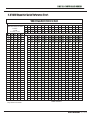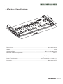
1
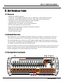
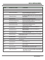
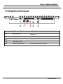
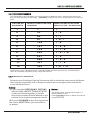
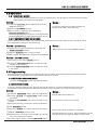
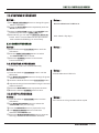
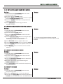
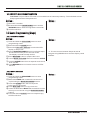
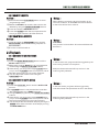
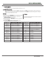
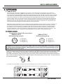
DMX 512 CONTROLLER SERIES
DMX-384
Version:1.0 28 Feb 2009
USER MANUAL
This product manual contains important information about the safe installation and
use of this projector. Please read and follow these instructions carefully and keep this
manual in a safe place for future reference.
DMX 512 CONTROLLER SERIES
Contents
1. Before you begin
1.1 What are included.................................. ....................................................... 2
1.2 Unpacking instructions ............................................................................... 2
1.3 Safety instructions .................................................................................... 2
2. Installation
2.1 Features ...................................................................................................
2.2 General overview.......................................................................................
2 .3 Product overview (front) ..............................................................................
2.4 Product overview (rear panel) .....................................................................
2.5 Common terms ...........................................................................................
3. Operating instructions
3
3
3
5
6
3.1 SETUP
3.1.1 Setting up the System .....................................................................
6
3.1.2 Fixture Addressing..........................................................................
7
3.1.3 Pan and tilt channels ......................................................................... 7
3.1.4 Resetting the system ........................................................................ 8
3.1.5 Copy Scanner ................................................................................. 8
3.1.6 Fade Time Assign.............................................................................. 8
3.2 OPERATION
3.2.1 Manual Mode... ....................................................................................................
9
3.2.2 Review Scene or Chase...................................................................
9
3.3 PROGRAMMING
3.3.1 Entering program mode.... ...............................................................................
9
3.3.2 Create a scene.................................................................................
9
3.3.3 Running a Program.......................................................................... 10
3.3.4 Check Program............................................................................... 10
3.3.5 Editing a Program........... ................................................................................ 10
3.3.6 Copy a Program...................... .....................................................................
10
3.4 CHASE PROGRAMMING
3.4.1 Create a chase...............................................................................
11
3.4.2 Running a Chase............................................................................. 11
3.4.3 Checking a Chase............................................................................ 11
3.4.4 Edit Chase (Copy Bank Into Chase)................................................... 11
3.4.5 Edit Chase (Copy Scene Into Chase)................................................. 12
3.4.6 Edit Chase (Insert Scene Into a Chase).............................................. 12
3.4.7 Delete a scene in a Chase................................................................. 12
3.4.8 Delete a Chase................................................................................. 12
3.4.9 Delete all Chase Programs............................................................... 13
3.5 SCENE PROGRAMMING (STEPS)
3.5.1 Insert a scene................................................................................... 13
3.5.2 Copy a scene................................................................................... 13
3.5.3 Delete a scene................................................................................ 14
3.5.4 Delete all scenes............................................................................. 14
3.6 PLAYBACK
3.6.1 Running in Sound-Mode.................................................................... 14
3.6.2 Running in Auto-Mode...................................................................... 14
3.6.3 Blackout ............................................................................................................... 15
3.7 MIDI OPERATION..................................................................................... 15
4 APPENDIX
4.1 DMX Primer...............................................................................................
4.2 Fixture Linking..........................................................................................
4.3 DMX dipswitch quick reference chart...........................................................
4.4 Technical specifications ............................................................................
16
16
17
18
USER MANUAL
1/18
DMX 512 CONTROLLER SERIES
1.1 What are included
1)
2)
3)
4)
DMX-512 Controller
DC 9-12V 500mA, 90V~240V Power Adapter
Manual
LED gooseneck lamp
1.2 Unpacking Instructions
Immediately upon receiving a fixture, carefully unpack the carton, check the
contents to ensure that all parts are present, and have been received in good
condition. Notify the shipper immediately and retain packing material for inspection if any parts appear damaged from shipping or the carton itself shows
signs of mishandling. Save the carton and all packing materials. In the event
that a fixture must be returned to the factory, it is important that the fixture be
returned in the original factory box and packing.
1.3 Safety Instructions
!
Please read these instructions carefully, which includes important
information about the installation, usage and maintenance .
* Please keep this User Guide for future consultation. If you sell the unit to another user, be sure that
they also receive this instruction booklet.
* Always make sure that you are connecting to the proper voltage and that the line voltage you are
connecting to is not higher than that stated on decal or rear panel of the fixture.
* This product is intended for indoor use only!
* To prevent risk of fire or shock, do not expose fixture to rain or moisture. Make sure there are no
flammable materials close to the unit while operating.
* The unit must be installed in a location with adequate ventilation, at least 50cm from adjacent
surfaces. Be sure that no ventilation slots are blocked.
* Always disconnect from power source before servicing or replacing lamp or fuse and be sure to
replace with same lamp source.
* In the event of serious operating problem, stop using the unit immediately. Never try to repair the unit
by yourself. Repairs carried out by unskilled people can lead to damage or malfunction. Please
contact the nearest authorized technical assistance center. Always use the same type spare parts.
* Don t connect the device to a dimmer pack.
* Make sure power cord is never crimped or damaged.
* Never disconnect power cord by pulling or tugging on the cord.
* Do not operate this device under 113 F ambient temperature conditions.
USER MANUAL
2/18
DMX 512 CONTROLLER SERIES
2. I NTRODUCTION
2.1 Features
* DMX512/1990 Standard
* Controls 12 intelligent lights of up to 32 channels, totally 384 channels
* 30 banks, each with 8 scenes; 6 chase, each with up to 240 scenes
* Record up to 6 chases with fade time and speeds
* 16 sliders for direct control of channels
* MIDI control over banks, chases and blackout
* Built-in microphone for music mode
* Auto mode program controlled by fade time sliders
* DMX in/out: 3 pin XRL
* LED gooseneck lamp
* Plastic end housing
2.2 General Overview
* The Controller is a universal intelligent lighting controller. It allows the control of
12 fixtures composed of 32 channels each and up to 240 programmable scenes.
Six chase banks can contain up to 240 steps composed of the saved scenes and
in any order. Programs can be triggered by music, midi,automatically or manually.
All chases can be executed at the same time.
* On the surface you will find various programming tools such as 16 universal channel
sliders, quick access scanner and scene buttons, and an LED display indicator for
easier navigation of controls and menu functions.
2.3 Product Overview (front)
8
16
D
INTELLIGENT LIGHTING CONTROLLER
17
10
10
10
10
10
10
10
10
10
10
10
10
10
10
8
8
8
8
8
8
8
8
8
8
8
8
8
8
6
6
6
6
6
6
6
6
6
6
6
6
6
6
6
4
4
4
4
4
4
4
4
4
4
4
4
4
4
4
2
2
2
2
2
2
2
2
2
2
2
2
2
2
2
0
0
0
0
0
0
0
0
0
0
0
Chase Scene Bank
A:1/16
TI
0
10
2
8
4
6
6
4
8
2
10
0
Auto
trigger
Program
8
DE
Music
trigger
Step
FA
STEP/TIME
Blackout
10
SP
EE
DMX 512
7
ME
18
4
30 SEC
0.1/SEC
B: 17/32
10 MIN
0
SCENES 1
SCENES 2
0
SCENES 3
SCENES 4
SCENES 5
SCENES 6
SCENES 8
SCENES 7
SCANNERS 1 SCANNERS 2 SCANNERS 3 SCANNERS 4 SCANNERS 5 SCANNERS 6 SCANNERS 7 SCANNERS 8 SCANNERS 9 SCANNERS 10 SCANNERS 11 SCANNERS 12
0
0
PAGE
SELECT
0 SEC
BANK UP
BANK DOWN
PROGRAM
MIDI/ADD
MUSIC BANK COPY
AUTO/DEL MUSIC BANK COPY TAPSYNC DISPLAY
CHASE 1
CHASE 2
CHASE 3
CHASE 4
CHASE 5
CHASE 6
BLACKOUT
DMX-384 OPERATOR
3
2
1
10
9 5 13 14 15 6 11 12
USER MANUAL
3/18
DMX 512 CONTROLLER SERIES
Item
Button or Fader
1
Scanner select buttons
Fixture selection
2
Scanner indicator LEDS
Indicates the fixtures currently selected
3
Scene select buttons
Universal bump buttons representing scene
location for storage and selection
4
Channel faders
For adjusting DMX values, Ch 1~32 can be adjusted
immediately after pressing the respective scanner
select button
5
Program button
Used to enter programming mode
6
Music/Bank Copy button
Used to activate Music mode and as the copy
command during programming
7
LED display window
Status window displays pertinent operational data
8
Mode Indicator LEDS
Provides operating mode status,
(manual, music or auto)
9
Bank Up button
Function button to traverse Scene/Steps in
banks or chases
10
Bank Down button
Function button to traverse Scene/Steps in
banks or chases
11
Tap Display button
Sets the chase speed by tapping, and toggles between
values and percentages.
12
Blackout button
Sets the shutter or dimmer value of all fixtures to
all light output to cease
13
Midi/ADD button
Activates MIDI external control and also used to confirm the
record/save process
14
Auto/Del button
Used to activate Auto mode and as the delete function key during
programming
15
Chaser buttons
Chase memory 1 ~ 6
16
Speed fader
This will adjust the hold time of a scene or a step
within a chase
17
Fade-Time fader
Also considered a cross-fade, sets the interval
time between two scenes in a chase
18
Page select button
Function
0
causing
In manual mode, press to toggle between pages
of control or to select both pages simultaneously.
Both LEDS on will allow control of both lower and
upper range channel.
USER MANUAL
4/18
DMX 512 CONTROLLER SERIES
2.4 Product Overview (rear panel)
SERIAL NO :
9V 1000mA
21
22
23
24
25
Item
Button or Fader
21
MIDI input port
For external triggering of Banks and Chases using a
MIDI device
22
DMX output connector
DMX control signal
23
DC Input jack
Main power feed
24
USB Lamp socket
25
ON/OFF power switch
Function
Turns the controller on and off
USER MANUAL
5/18
DMX 512 CONTROLLER SERIES
2.5 Common Terms
The following are common terms used in intelligent light programming.
Blackout is a state by where all lighting fixtures light output are set to 0 or off, usually on a temporary
basis.
DMX-512 is an industry standard digital communication protocol used in entertainment lighting
equipment. For more information read Sections DMX Primer and DMX Control Mode in the
Appendix.
Fixture refers to your lighting instrument or other device such as a fogger or dimmer of which you can
control.
Programs are a bunch of scenes stacked one after another. It can be programmed as either a single
scene or multiple scenes in sequence.
Scenes are static lighting states.
Sliders also known as faders.
Chases can also be called programs. A chase consists of a bunch of scenes stacked one after
another.
Scanner refers to a lighting instrument with a pan and tilt mirror; however, in the ILS-CON controller it
can be used to control any DMX-512 compatible device as a generic fixture.
MIDI is a standard for representing musical information in a digital format. A MIDI input would provide
external triggering of scenes using midi device such as a midi keyboard.
Stand Alone refers to a fixture s ability to function independently of an external controller and usually
in sync to music, due to a built in microphone.
Fade slider is used to adjust the time between scenes within a chase.
Speed slider affects the amount of time a scene will hold its state. It is also considered a wait time.
Shutter is a mechanical device in the lighting fixture that allows you to block the lights path. It is often
used to lessen the intensity of the light output and to strobe.
Patching refers to the process of assigning fixtures a DMX channel or.
Playbacks can be either scenes or chases that are directly called to execution by the user. A playback
can also be considered program memory that can be recalled during a show.
3.OPERATING INSTRUCTIONS
3.1 Setup
3.1.1 SETTING UP THE SYSTEM
1) Plug the AC to DC power supply to the system back panel and to the mains outlet.
2) Plug in your DMX cable(s) to your intelligent lighting as described in the fixtures respective
manual. For a quick Primer on DMX see the “ DMX Primer ” section in the Appendix of this
manual.
USER MANUAL
6/18
DMX 512 CONTROLLER SERIES
3.1.2 FIXTURE ADDRESSING
The Controller is programmed to control 32 channels of DMX per fixture, therefore the fixtures you
wish to control with the corresponding SCANNER buttons on the unit, must be spaced 16 channels
apart.
FIXTURE OR
SCANNER #
DEFAULT DMX STARTING
ADDRESS
1
2
3
4
5
6
7
8
9
10
11
12
1
33
65
97
129
161
193
225
257
289
321
353
BINARY DIPSWITCH SETTINGS
SWITCH TO THE ON POSITION
1
1
1
1
1
1
1
1
1
1
1
1
,6
,7
,6 ,7
,8
,6,8
,7,8
, 6 , 7 ,8
,9
,6,9
,7,9
,6 ,7 , 9
Please refer to your individual fixture s manual for DMX addressing instructions. The table above
refers to a standard 9 dipswitch binary configurable device.
3.1.3 PAN AND TILT CHANNELS
Because not all intelligent lighting fixtures are alike or share the same control attributes,
the Controller allows the user to assign the wheel the correct pan and tilt channel for
every individual fixture
Action :
1) Press and hold PROGRAM & TAPSYNC
different DMX channel. Faders are given
a channel buttons together (1) time to
access the number and are labeled on the
surface of the channel assignment mode.
Notes :
All pan/tilt can be reassigned to output on a
different DMX channel.
Press AUTO/DEL buttons to delete the channel
assignment mode.
2) Press a SCANNER button that represents
the fixture whose faders you would like to
re-assign.
USER MANUAL
7/18
DMX 512 CONTROLLER SERIES
3) Move one fader of 1-32 channel to select
the pan channel.
4) Press the TAPSYNC DISPLAY button to
select pan / tilt
5) Move one fader of 1-32 channel to select
the tilt channel.
6) press and hold PROGRAM & TAPSYNC DISPLY
Notes :
All pan/tilt can be reassigned to output on a
different DMX channel.
buttons to exit and save setting. All LEDs will blink.
3.1.4 RESETTING THE SYSTEM
Warning:
this will reset the controller to its factory defaults.
This will erase all programs and settings.
Notes :
Action :
1) Turn off the unit.
2) Press and hold BANK UP and AUTO/DEL.
3) Turn on power to the unit (while still holding
BANK UP and AUTO/DEL).
3.1.5 COPY SCANNER
Example: Copying Scanner 1 into Scanner 2
Action :
Notes :
1 ) Press and hold SCANNER button # 1.
2) While holding button # 1 press SCANNER button # 2.
To save time, you can copy the settings of one
Scanner button to another.
3) Release SCANNER button # 1 first before releasing
SCANNER button # 2.
4) All SCANNER LED indicators will flash to confirm
successful copy.
3.1.6 FADE TIME ASSIGN
You can choose whether the board s fade time during scene execution is implemented broadly to all
output channels or only to the Pan & Tilt movement channels. This is relevant because often you will
want gobos and colors to change quickly while not affecting the movement of the light.
Action :
Notes :
1) Turn OFF the controller.
2) Hold the BLACKOUT and TAPSYNC DISPLAY
buttons simultaneously.
3) Turn ON the controller.
4) Press the TAPSYNC DISPLAY button to toggle
between the two modes. Either all channels (A) or
select channel Pan & Tilt only (P)
A: All channels
P: Only Pan & Tilt
5) Press BLACKOUT and TAPSYNC DISPLAY to save
settings. All LEDs will blink to confirm.
USER MANUAL
8/18
DMX 512 CONTROLLER SERIES
3.2 Operation
3.2.1 MANUAL MODE
The manual mode allows direct control of all scanners. You are able to move them and change
attributes by using the channel faders.
Action :
1 ) Press the AUTO DEL button repeatedly until the
MANUAL LED is lit.
2) Select a SCANNER button.
Notes :
All changes made while in Manual Mode are
temporary and will not be recorded.
3) Move faders to change fixture attributes.
TAPSYNC DISPLAY button:
Press to toggle the output indicator on the LED display
between DMX values (0-255) and percentage (0-100)
3.2.2 REVIEW SCENE OR CHASE
This instruction assumes that you have already recorded scenes and chases on the controller. Other
wise skip section and go to programming.
Action : ( SCENE Review)
1) Select any one of the 30 banks by pressing the
BANK UP/DOWN buttons.
2) Select a SCENE button (1~8) to review.
Notes :
Make sure you are still in MANUAL Mode.
3) Move wheel and faders to change fixture attributes.
Action : ( CHASE Review )
1) Press any one of the 6 CHASE buttons.
2) Press the TAP DISPLAY button to view the step
number on the display.
3) Press the BANK UP/DOWN buttons review all scenes
in the chase.
3.3 Programming
A program (bank) is a sequence of different scenes (or steps) that will be called up one after another.
In the controller 30 programs can be created of 8 scenes in each.
3.3.1ENTERING PROGRAM MODE
1 ) Press the Program button until the LED blinks.
3.3.2CREATE A SCENE :
A scene is a static lighting state. Scenes are stored in banks. There are 30 bank memories on the
controller and each bank can hold 8 scene memories. The controller can save 240 scenes total.
Action :
1 ) Press the PROGRAM button until the LED blinks.
2) Position SPEED and FADE TIME sliders all the
Notes :
Deselect Blackout if LED is lit.
way down.
3) Select the SCANNERS you wish to include in your
scene.
4) Compose a look by moving the sliders and wheel.
5) Tap MIDI/REC button.
6) Choose a BANK (01~30) to change if necessary.
7) Select a SCENES button to store.
8) Repeat steps 3 through 7 as necessary. 8 scenes
You can select more than one fixture.
There are 8 scenes available in every bank.
All LEDs will flash to confirm. The LED display will now
indicate the Scene number and Bank number used.
can be recorded in a Program.
9) To exit program mode, hold the PROGRAM button.
USER MANUAL
9/18
DMX 512 CONTROLLER SERIES
3.3.3 RUNNING A PROGRAM
Action :
1) Use BANK UP/DOWN buttons to change Program
banks if necessary.
2) Press the AUTO DEL button repeatedly until the
AUTO LED turns on.
Notes :
Deselect Blackout if LED is lit.
3) Adjust the PROGRAM speed via the SPEED fader
and the loop rate via the FADE TIME fader.
4) Alternatively you can tap the TAPSYNC DISPLAY
button twice. The time between two taps sets the
time between SCENES (up to 10 minutes).
Also called a Tap-Sync.
3.3.4 CHECK PROGRAM
Action :
1) Press and hold the PROGRAM button until the
Notes :
LED blinks.
2) Use the BANK UP/DOWN buttons to select
the PROGRAM bank to review.
3) Press the SCENES buttons to review each
scene individually.
3.3.5 EDITING A PROGRAM
S cenes
will need to be modified manually.
Action :
1 ) Press and hold the PROGRAM button until the
LED blinks.
2) Use BANK UP/DOWN buttons to change Program
banks if necessary.
3) Select the desired fixture via the SCANNERS button.
Notes :
Deselect Blackout if LED is lit.
4) Adjust and change fixture attributes using the channel
faders and wheel.
5) Press the MIDI/ADD button to prepare the save.
6) Select the desired SCENES button to save.
3.3.6 COPY A PROGRAM
Action :
1 ) Press and hold the PROGRAM button until the
LED blinks.
2) Use BANK UP/DOWN buttons to select the
PROGRAM bank you will copy.
3) Press the MIDI/ADD button to prepare the copy.
Notes :
All 8 scenes in a Program bank will be copied.
4) Use BANK UP/DOWN buttons to select the
destination PROGRAM bank.
5) Press the MUSIC BANK COPY button to execute
the copy. All LEDs on the controller will blink.
USER MANUAL
10/18
DMX 512 CONTROLLER SERIES
3.4 Chase Programming
A chase is created by using previously created scenes. Scenes become steps in a chase and can be
arranged in any order you choose. It is highly recommended that prior to programming chases for the
first time; you delete all chases from memory. See Delete All Chases for instructions.
3.4.1 CREATE A CHASE
A Chase can contain 240 scenes as steps. The term steps and scenes are used interchangeably.
Action :
1) Press the PROGRAM button until the LED blinks.
2) Press the CHASE (1~6) button you wish to program.
3) Change BANK if necessary to locate a scene.
4) Select the SCENE to insert.
5) Tap the MIDI/ADD button to store.
6) Repeat steps 3 ~ 5 to add additional steps in the
Notes :
chase. Up to 240 steps can be recorded.
7) Press and hold the PROGRAM button to save the
chase.
3.4.2 RUNNING A CHASE
Action :
1 ) Press a CHASE button then press the AUTO DEL
button.
2) Adjust the Chase speed by tapping the TAPSYNC DISPLAY button twice at a rate of your choosing.
Notes :
The time between 2 taps will set the chase speed (up
to 10 minutes)
3.4.3 CHECKING A CHASE
Action :
Notes :
1 ) Press and hold the PROGRAM button until the LED
is light.
2) Select the desired CHASE button.
3) Press the TAPSYNC DISPLAY button to switch the
LED display to steps.
4) Review each scene/step individually by using the
BANK UP/DOWN buttons.
3.4.4 EDIT CHASE (COPY BANK INTO CHASE)
Action :
Notes :
1 ) Press and hold the PROGRAM button to enter
programming mode.
2) Press the desired CHASE button.
3) Select the BANK to be copied using the
BANK UP/DOWN buttons.
4) Press MUSIC/BANK COPY button to prepare copy.
5) Press MIDI/ADD button to copy the bank. All LEDs
will blink.
USER MANUAL
11/18
DMX 512 CONTROLLER SERIES
3.4.5 EDIT CHASE (COPY SCENE INTO CHASE)
Action :
1) Press and hold the PROGRAM button to enter
Notes :
programming mode.
2) Press the desired CHASE button.
3) Select the BANK that contains the scene to be copied
using the BANK UP/DOWN buttons.
4) Press the SCENE button that corresponds to the
scene to be copied.
5) Press MIDI/ADD button to copy the scene.
All LEDs will blink.
3.4.6 EDIT CHASE (INSERT SCENE INTO A CHASE)
Action :
Notes :
1 ) Press and hold the PROGRAM button to enter
programming mode.
2) Press the desired CHASE button.
3) Press the TAPSYNC DISPLAY to switch the LED
display to steps view.
4) Use the BANK UP/DOWN buttons to navigate steps
and locate the insert point of the new scene.
The display will read the step number.
5) Press MIDI/ADD button to prepare the insert.
I .e. To insert a scene between Steps 05 and 06
navigate using BANK buttons until the display reads
STEP05.
6) Use the BANK UP/DOWN button to locate the SCENE .
7) Press the SCENE button that corresponds to the scene
to be inserted.
8) Press MIDI/ADD button to insert the scene. All LEDs
will blink.
3.4.7 DELETE A SCENE IN A CHASE
Action :
Notes :
1 ) Press and hold the PROGRAM button to enter
programming mode.
2) Press the desired CHASE button that contains
the scene to be deleted.
3) Press the TAPSYNC DISPLAY button to switch the
LED display to steps.
4) Select the scene/step to be deleted using the
BANK UP/DOWN buttons.
5) Press AUTO DEL button to delete the step/scene.
All LEDs will blink.
3.4.8 DELETE A CHASE
Action :
Notes :
1 ) Press and hold the PROGRAM button to enter
programming mode.
2) Press the CHASE button (1~6) to be deleted.
3) Press and hold AUTO DEL button and the respective
CHASE button to delete the chase. All LEDs will blink.
USER MANUAL
12/18
DMX 512 CONTROLLER SERIES
3.4.9 DELETE ALL CHASE PROGRAMS
CAUTION! This procedure will result in irrevocable loss of chase step memory. The individual scenes
and program banks will be preserved.
Action :
1) Turn OFF controller.
2) Press and hold the BANK DOWN button and the
Notes :
AUTO DEL button while turning ON the controller.
3) All LEDs will blink.
3.5 Scene Programming (Steps)
3.5.1 INSERT A SCENE
Action :
Notes :
1 ) Press and hold the PROGRAM button to enter
programming mode.
2) Press the desired CHASE button.
3) Press the TAPSYNC DISPLAY to switch the LED
display to steps view.
4) Use the BANK UP/DOWN buttons to navigate steps
and locate the insert point of the new scene.
The display will read the step number.
5) Press MIDI/ADD button to prepare the insert.
I .e. To insert a scene between Steps 05 and 06
navigate using BANK buttons until the display reads
STEP05.
6) Use the BANK UP/DOWN button to locate the SCENE .
7) Press the SCENE button that corresponds to the scene
to be inserted.
8) Press MIDI/ADD button to insert the scene. All LEDs
will blink.
3.5.2 COPY A SCENE
Action :
Notes :
1 ) Press and hold the PROGRAM button to enter
programming mode.
2) Select the BANK that contains the scene to be
copied using the BANK UP/DOWN buttons.
3) Press the SCENE button that corresponds
to the scene to be copied.
4) Press MIDI/ADD button to copy the scene.
5) Select the destination BANK that contains the scene
memory to record onto using the BANK UP/DOWN
buttons.
6) Press the desired SCENE button to complete copy.
All LEDs will blink.
USER MANUAL
13/18
DMX 512 CONTROLLER SERIES
3.5.3 DELETE A SCENE
Action :
1) Press and hold the PROGRAM button to enter
programming mode.
2) Select the BANK that contains the scene to be
deleted by using the BANK UP/DOWN buttons.
3) Press and hold the AUTO DEL button.
4) Press the SCENE button that corresponds to the
scene you want to delete. All LEDs will blink.
Notes :
When deleting a scene the physical location is not
removed, however, all 384 DMX channels available
to the scene will be set to value 0.
3.5.4 DELETE ALL SCENES
Action :
1 ) Press and hold the PROGRAM button and the
BANK DOWN button while turning off power to
the controller.
2) Turn the controller back on.
Notes :
CAUTION!
This process is irreversible. All scenes with data will
be set to 0.
3.6 Playback
3.6.1 RUNNING IN SOUND-MODE
Action :
1 ) Press the MUSIC BANK COPY button until the
MUSIC LED turns on.
2) Select the program BANK to run in soundactive
mode using the BANK UP/DOWN buttons.
3) Alternatively you can press a single CHASE button
(1~6) or several CHASE buttons in sequence and all
selected chases will loop in the order selected.
4) You can adjust the duration time using the
FADE TIME fader.
Notes :
In the Sound mode, programs will be triggered by the
sound using its built-in microphone.
Multiple chases selected will loop and run in the
order originally selected.
3.6.2 RUNNING IN AUTO-MODE
Action :
1 ) Press the AUTO DEL button until the AUTO LED
turns on.
2) If a CHASE button is not pressed the controller
will automatically run a BANK program.
3) Change BANK programs by using BANK UP/DOWN
buttons.
4) Alternatively you can press a single CHASE button
(1~6) or several CHASE buttons in sequence and all
selected chases will loop in the order selected.
5) You can adjust the time between steps by moving the
SPEED fader and the duration of the step by moving
the FADE TIME fader.
Notes :
In the Auto mode, programs will be triggered by
controllers fade and speed time as set on the faders.
Multiple chases selected will loop and run in the
order originally selected.
USER MANUAL
14/18
DMX 512 CONTROLLER SERIES
3.6.3 BLACKOUT
The Blackout button brings all lighting output to 0 or off.
3.7 Midi Operation
The controller will only respond to MID I commands on the MIDI channel which it is set to full stop. All
MIDI control is performed using Note on commands. All other MIDI instructions are ignored. To stop a
chase, send the blackout on note.
Action :
Notes :
1 )Press and hold the MIDI/ADD button for about 3 seconds.
2) Select the MIDI control channel (1~16) via the
BANK UP/DOWN buttons to set.
3) Press and hold the MIDI/ADD button for 3 seconds
to save settings.
4) To release MIDI control, press any other button
except the BANK buttons during step 2.
MIDI NOTE
FUNCTION (TURN ON/OFF)
This is the Channel that the controller will receive
MIDI note commands.
MIDI NOTE
FUNCTION (TURN ON/OFF)
00 to 07
Scenes 1~8 in BANK 1
88 to 95
Scenes 1~8 in BANK 12
08 to 15
Scenes 1~8 in BANK 2
96 to 103
Scenes 1~8 in BANK 13
16 to 23
Scenes 1~8 in BANK 3
104 to 111
Scenes 1~8 in BANK 14
24 to 31
Scenes 1~8 in BANK 4
112 to 119
Scenes 1~8 in BANK 15
32 to 39
Scenes 1~8 in BANK 5
120
Chase 1
40 to 47
Scenes 1~8 in BANK 6
121
Chase 2
48 to 55
Scenes 1~8 in BANK 7
122
Chase 3
56 to 63
Scenes 1~8 in BANK 8
123
Chase 4
64 to 71
Scenes 1~8 in BANK 9
124
Chase 5
72 to 79
Scenes 1~8 in BANK 10
125
Chase 6
80 to 87
Scenes 1~8 in BANK 11
126
BLACKOUT
USER MANUAL
15/18
DMX 512 CONTROLLER SERIES
4 APPENDIX
4.1 DMX Primer
There are 512 channels in a DMX-512 connection. Channels may be assigned in any manner. A
fixture capable of receiving DMX 512 will require one or a number of sequential channels. The user
must assign a starting address on the fixture that indicates the first channel reserved in the controller.
There are many different types of DMX controllable fixtures and they all may vary in the total number
of channels required. Choosing a start address should be planned in advance. Channels should
never overlap. If they do, this will result in erratic operation of the fixtures whose starting address is
set incorrectly. You can however, control multiple fixtures of the same type using the same starting
address as long as the intended result is that of unison movement or operation. In other words, the
fixtures will be slaved together and all respond exactly the same.
DMX fixtures are designed to receive data through a serial Daisy Chain. A Daisy Chain connection is
where the DATA OUT of one fixture connects to the DATA IN of the next fixture. The order in which
the fixtures are connected is not important and has no effect on how a controller communicates to
each fixture. Use an order that provides for the easiest and most direct cabling. Connect fixtures
using shielded two conductor twisted pair cable with three pin XLR male to female connectors. The
shield connection is pin 1, while pin 2 is Data Negative (S-) and pin 3 is Data positive (S+).
4.2 FIXTURE LINKING
Occupation of the XLR-connection:
DMX-OUTPUT
XLR mounting-plug:
DMX-OUTPUT
XLR mounting-socket:
1 - Ground
2 - Signal (-)
3 - Signal (+)
1 - Ground
2 - Signal (-)
3 - Signal (+)
Caution: At the last fixture, the DMX-cable has to be terminated with a terminator. Solder
a 120 resistor between Signal (-) and Signal (+) into a 3-pin XLR-plug and plug it in the
DMX-output of the last fixture.
I n the Controller mode, at the last fixture in the chain, the DMX output has to be connected with a DMX
terminator. This prevents electrical noise from disturbing and corrupting the DMX control signals.
The DMX terminator is simply an XLR connector with a 120W (ohm) resistor connected across pins 2
and 3, which is then plugged into the output socket on the last projector in the chain. The connections
are illustrated below.
120 ohm
PIN2
PIN3
If you wish to connect DMX-controllers with other XLR-outputs, you need to use adapter-cables.
The transform of the controller line of 3 pins and 5 pins (plug and socket)
USER MANUAL
16/18
DMX 512 CONTROLLER SERIES
4.3 DMX Dipswitch Quick Reference Chart
DMX Address Quick Reference Chart
Dip Switch Position
#9
DMX DIP SWITCH SET
#8
0=OFF
#7
1=ON
X=OFF or ON
#6
#1 #2 #3 #4 #5
0
0
0
0
0
0
0
0
0
1
0
0
0
1
0
0
0
0
1
1
0
0
1
0
0
0
0
1
0
1
0
0
1
1
0
0
0
1
1
1
0
1
0
0
0
0
1
0
0
1
0
1
0
1
0
0
1
0
1
1
0
1
1
0
0
0
1
1
0
1
0
1
1
1
0
0
1
1
1
1
1
0
0
0
0
1
0
0
0
1
1
0
0
1
0
1
0
0
1
1
1
0
1
0
0
1
0
1
0
1
1
0
1
1
0
1
0
1
1
1
1
1
0
0
0
1
1
0
0
1
1
1
0
1
0
1
1
0
1
1
1
1
1
0
0
1
1
1
0
1
1
1
1
1
0
1
1
1
1
1
Dip Switch Position
0
0
0
0
0
0
0
1
0
0
1
0
0
0
1
1
0
1
0
0
0
1
0
1
0
1
1
0
0
1
1
1
1
0
0
0
1
0
0
1
1
0
1
0
1
0
1
1
1
1
0
0
1
1
0
1
1
1
1
0
1
1
1
1
1
2
3
4
5
6
7
8
9
10
11
12
13
14
15
16
17
18
19
20
21
22
23
24
25
26
27
28
29
30
31
32
33
34
35
36
37
38
39
40
41
42
43
44
45
46
47
48
49
50
51
52
53
54
55
56
57
58
59
60
61
62
63
64
65
66
67
68
69
70
71
72
73
74
75
76
77
78
79
80
81
82
83
84
85
86
87
88
89
90
91
92
93
94
95
96
97
98
99
100
101
102
103
104
105
106
107
108
109
110
111
112
113
114
115
116
117
118
119
120
121
122
123
124
125
126
127
128
129
130
131
132
133
134
135
136
137
138
139
140
141
142
143
144
145
146
147
148
149
150
151
152
153
154
155
156
157
158
159
160
161
162
163
164
165
166
167
168
169
170
171
172
173
174
175
176
177
178
179
180
181
182
183
184
185
186
187
188
189
190
191
192
193
194
195
196
197
198
199
200
201
202
203
204
205
206
207
208
209
210
211
212
213
214
215
216
217
218
219
220
221
222
223
224
225
226
227
228
229
230
231
232
233
234
235
236
237
238
239
240
241
242
243
244
245
246
247
248
249
250
251
252
253
254
255
256
257
258
259
260
261
262
263
264
265
266
267
268
269
270
271
272
273
274
275
276
277
278
279
280
281
282
283
284
285
286
287
288
289
290
291
292
293
294
295
296
297
298
299
300
301
302
303
304
305
306
307
308
309
310
311
312
313
314
315
316
317
318
319
320
321
322
323
324
325
326
327
328
329
330
331
332
333
334
335
336
337
338
339
340
341
342
343
344
345
346
347
348
349
350
351
352
353
354
355
356
357
358
359
360
361
362
363
364
365
366
367
368
369
370
371
372
373
374
375
376
377
378
379
380
381
382
383
384
385
386
387
388
389
390
391
392
393
394
395
396
397
398
399
400
401
402
403
404
405
406
407
408
409
410
411
412
413
414
415
416
417
418
419
420
421
422
423
424
425
426
427
428
429
430
431
432
433
434
435
436
437
438
439
440
441
442
443
444
445
446
447
448
449
450
451
452
453
454
455
456
457
458
459
460
461
462
463
464
465
466
467
468
469
470
471
472
473
474
475
476
477
478
479
480
481
482
483
484
485
486
487
488
489
490
491
492
493
494
495
496
497
498
499
500
501
502
503
504
505
506
507
508
509
510
511
DMX Address
USER MANUAL
17/18
DMX 512 CONTROLLER SERIES
4.4 Technical Specifications
3m
m
73m
m
18
520
mm
Dimensions.................................................................................................. 520 X183 X73 mm
Weight........................................................................................................................... 3.0 Kg
Operating Range.....................................................................................DC 9V-12V 500mA min
Maximum ambient temperature.......................................................................................45
C
Data input .................................................................................. locking 3-pin XLR male socket
Data output ............................................................................. locking 3-pin XLR female socket
Data pin configuration ..................................................................pin 1 shield, pin 2 (-), pin 3 (+)
Protocols........................................................................................................DMX-512 USITT
USER MANUAL
18/18