1
EprUsb / Lpc-32Usb
Programmer for EPROMS, parallels EEPROMS
And FLASHs on USB port
USER MANUAL
(Software release 1.7 (Windows XP 32bits) and software release 2.0 (Windows 7 64 bits)
User Manual Release 2.0 (June 2012)
Product contents:
- A programmer.
- A USB cord of type A-B.
- A user manual.
- A CD-ROM contains Epr-Usb and Lpc-32Usb software for Windows 32bits and 64bits and user manual.
Presentation:
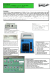
The EprUsb and Lpc-32Usb allows programming at the lowest cost a wide range of FLASH memories
(28Cxxx, 28Fxxx, 29xxx, 37xxx, 39xxx, 49xxx) in DIP32 and PLCC32 boxes through these two supports
soldered on the printed circuit in standard version. It allows reprogramming, for example, the BIOS of
motherboards or flash memories for the production of prototypes. It supports standard components (5.0V) and
low-voltages (2.7V - 3.3V). The EprUsb and the Lpc-32Usb is protected against all inversely inserted
components and short-circuits. It is connected to the USB port of your PC and does not require any external
power supply. The software works under Windows 98/ME/2000/XP (32bits) for the release 1.7 and works
under Windows XP/VISTA/Win7 (64 bits) for the release 2.0.
List of components supported by EprUsb and Lpc-32Usb (Release 1.7 -> 32bits / Release 2.0 -> 64bits) :
Am27C64
Am27C128
Am27C256
Am27C512
Am27C010
Am27C020
Am28F256
Am29F010
Am29LV010B
Am28F512
Am29F010A
Am29LV040B
Am28F010
Am29F010B
Am28F020
Am29F040
Am29F040A
Am29F040B
Atmel
AT28C17
AT28HC256F
AT28C17E
AT28C64B
AT28C256
AT28C256E
AT28C256F
CATALYST
CAT28F512
CAT28F512I
CAT28F010
CAT28F010I
CAT28F020
CAT28F020I
FUJITSU
MBM28F010
ISSI
IS28F010
MITSUBISHI
M5M28F101
PMC
PM49FL002T
PM49FL004T
PM49FL008T
SST
SST27SF256
SST28LF040
SST37VF512
SST39LF512
SST39SF512
SST39VF512
SST49LF002
SST49LF004
SST27SF512
SST28SF040
SST37VF010
SST39LF010
SST39SF512A
SST39VF010
SST49LF002A
SST49LF004A
SST27SF010
SST28SF040A
SST37VF020
SST39LF020
SST39SF010
SST39VF020
SST49LF002B
SST49LF004B
SST27SF020
SST28VF040
SST37VF040
SST39LF040
SST39SF010A
SST39VF040
SST49LF020
SST49LF040
SST27VF256
SST28VF040A
M2764A
M27C4001
M28F256
M29F010B
M27C64A
M27C801
M28F512
M29F040
M27128A
M27256
M28F101
M29F040B
M28F201
SyncMOS
S29C51001B
S29C51001T
S29C51002B
Textas-Instr.
TMS28F512
TMS28F010
TMS28F020
Winbond
W39V040A
W39V040FA
W49F002
W49F002B
W49F002
W49F002B
W49V002A
W49V002FA
X2816A
X2816B
AMD
ST-Micro.
Xicor
Am27C040
AT28HC256
AT28HC256E
SST27VF512
SST27VF010
SST27VF020
SST39SF020
SST39SF020A
SST39SF040
SST49LF020A
SST49LF040A
SST49LF003A
SST49LF040B
SST49LF003B SST49LF030A
SST49LF008/A SST49LF080A
M27512
M27C1000
M27C1001
M27C2001
S29C51002T
S29C51004B
S29C51004T
W39V040B
W39V040FB
W39V040C
W39V040FC
W39V080A
W39V080FA
W49F002N
W49F002U
W49F020
W49F002N
W49F002U
W49F020
W49V002FP
W49V002P
X2816C
X28C16A
X28C16B
X28C16C
X28HC16
X28C64
X28VC256
X28C512
X28LC512
X28LC513
X28C010
IS28F020
X28HC64
X28C256
X28HC256
XM28C010
XM28C020
XM28C040
W27E512
1) Instaling JAVA system on your computer (release 2.0 (64bits) only) :
Epr-Usb and Lpc-32Usb programmers need JAVA to run for the release 2.0 (64bits) only. If you install the
release V1.7 (32bits) you don’t need to install JAVA on your computer.
If Java is already installed on your computer, you can swith the following chapter :
Java Setup
You can find Java on the CD-ROM provided.
To start the install, open the file "Java_V6.0.240.exe".
If you got a message : "Do you want to allow the following program to make changes to this computer ?" ,
answer « YES »
Java install begins.
Select "Install >" to start the install of java.
It can last for a few minutes.
Once the setup is complete, you receive this message.
Click on « Close » to close the window.
2) Software installation (release 1.7 (32bits) and release 2.0 (64bits) :
Start by installing the software on your hard disk from the CD-ROM supplied. If you do not have a CD-ROM
drive, you can download this software from our Internet site from the following URL: http://www.seeit.fr, link «
Download ». On the Internet, the software is available in a compressed ZIP file. Extract the files from the zip to
your hard disc, and then run the file « Setup.exe ». Follow the software installation procedure.
If you got a message "Do you want to allow the following program to make changes to this computer ?" ,
answer « YES »
Software install begins.
Select your language and click on « OK »
Choose "Next”
Choose the folder where you want FlashBios to be installed, then click on "Next".
The default folder is : "C:\Program Files\EprUsb".
Choose the name of the folder for the Start menu shortcuts and click on "Next".
The default name is "EprUsb".
You can have additional shortcuts. Choose your options and click on "Next".
You can now start the install by clicking on "Install".
Click on "Finish" to complete the installation.
3) USB driver installation (release 1.7 (32bits) only :
Now, connect the programmer to a USB port of your PC.
Windows opens a new window « New hardware detected ».
Click the button « Not this time » and click on « Next ».
Click the button « Install the software manually » and click on « Next ».
When Windows asks you to indicate the access path of the file, go to the folder « C:\Program
Files\EprUsb\driver » then, click on « OK ».
After installing the driver, click on « Finish ».
4) USB driver installation (release 2.0 (64bits) only :
In order to communicate with the programming card, you have to install the drivers of the card. Without it, the
programmer can’t work.
The software needs two drivers, and the install is the same for each of them.
To start the drivers installation, plug the programming card to your computer with an USB cable.
You receive this message in the lower right corner of your screen.
Wait until this message becomes:
Go to the Start menu then "Control Panel"
Go to the "Device Manager". There are two ways to go to the "Device Manager", depending of your display.
Display 1 :
If your "Control Panel" looks like that :
Go to "System and Security".
Then go to "Device Manager".
Display 2 :
If your "Control Panel" looks like that :
You can directly click on "Device Manager".
Once you are in the "Device Manager", you can see this screen :
Your list can change from our exemple, it depands of your hardware.. However, you must have a "Unknown
device" in this list : it’s the programming card
In order ton install the drivers, select this "Unknown device".
The values for the location can be differents from ours. Click on "Update driver..."
Choose the second option, "Browse my computer for driver software"
Click on "Browse...", and select the "driver" fodler located in the EprUsb folder where you have installed the
software. In our example , we didn’t change the default folder, so the "driver" folder is located at
"C:\Program Files\EprUsb\driver".
Click on Next.
Choose the second option, "Install this driver software anyway".
The install begins.
Click on "Close" to finish the install of the first driver
Close the EprUsb Properties screen, which was a Unknow device just before.
You are now back on the Device Manager : the Unknow device disappear from the list. Instead, EprUsb
appeared.
5) First open of the software (release 1.7 (32bits) and release 2.0 (64bits) :
Run the software EprUsb.
Click on "OK" in the pop-up message, then go in the "Component" menu and click on "Select".
Choose a component in the list, then click on "Choose this component".
After choosing a component and for the first open only, Windows ask you to install the second USB driver.
In this case follow the same procedure as before:
« 3) USB driver installation (release 1.7 (32bits) only : »
Or :
« 4) USB driver installation (release 2.0 (64bits) only : »
6) Software procedure (release 1.7 (32bits) and release 2.0 (64bits):
Insertion and extraction of a component:
It is preferable to insert the component on its support only after starting the software and selecting a component
from the list. Similarly, you must extract your component before quitting the software or changing the
component reference in the list.
The components must be oriented correctly during their insertion, even though the programmer is protected
against short-circuits and insertions errors, you may damage your component if you do use it in the right
direction. The pin 1 is identified on the printed circuit by the number « 1 ». On the component, the pin « 1 » is
marked either by a by a point on the PLCC32 components, or by a notch on top of the component.
For extracting a component from the PLCC32 without damaging it, use preferably a small flat screwdriver of 1
mm width. Slide the flat of the screwdriver under the square component from one of the corners of the support
and apply a slight leverage. Place the screwdriver in the same way under the opposite corner and apply a slight
leverage. The component should be extracted without forcing.
Erasing a component:
The menu « Component\Erase » is sometimes unavailable. This signifies that the component cannot be erased.
The EPROMs of type 27Cxxx can be erased only by using an EPROM eraser based on UV such as the LER121A.
The parallel EEPROMs of type 28Cxxx and 29Cxxx reprogrammable directly without first erasing them.
The FLASHs of type 28Fxxx, 29Fxxx, 39Fxxx, 49Fxxx can be erased electrically using the menu «
Component\Erase ».
Loading a file:
The menu « File\Load » allows loading a source file in the window of the tab « Program0 » before going ahead
with a programming. This window is called the « Buffer Program ». It serves as the intermediary between the
loading of the file source code into the software, then from the software to the component that has to be
programmed.
When you use the « File\Load », if the file that you wish to load does not appear in the window « Load », select
« All files » in the menu « File Type » in the bottom of the window. After selecting the file, click on « Open ».
If the file loaded into the buffer is of a size that does not correspond to the type of component selected, a
warning message will be displayed on the screen. If the file loaded is of a larger size, it will be truncated. If the
file is of a smaller size, the remaining space of the buffer shall be loaded with the value 0xFF. Normally, the
size of the file loaded must correspond to the size of the component.
The two buffers “Program0” and “Program1”:
You can use indifferently one or other of the two tabs for loading a file on the screen. These two tabs «
Program0 » and « Program1 » are provided so that one may compare if required two files side by side through
the menu « Edit\Compare ». For example, you can select the buffer « Program0 » for loading your source code
on the screen. You may then program your component. Then you load the buffer « Program1 » for reading your
component. You can then compare the two buffers.
Programming a component:
After this, run the EprUsb software. A window is displayed asking you to select a component.
Use the menu « Component\Select ». Highlight a component, then click on « Select this component ».
Insert the component on the support.
Open your file using the menu « File\Load ».
If you are not sure that your component is blank, use first the menu « Component\Blank Check ».
Start the programming of the component using the menu « Component\Program ».
Verify the programming of your component using the menu « Component\Verify ».
If the verification is « OK », your component has been programmed successfully.