1
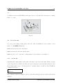
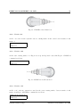
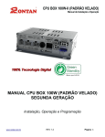
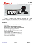
User’s Manual for A4 Head
System Control Department
KIHEUNG MACHINERY COMPANY, LTD
List of Contents
1 A4 Head
1
1.1
Components of A4 Head . . . . . . . . . . . . . . . . . . . . . . . . . . . . . . . .
1
1.2
Heidenhain NC Function for A4 Head . . . . . . . . . . . . . . . . . . . . . . . .
2
2 Reference System
2
2.1
Transverse Axis . . . . . . . . . . . . . . . . . . . . . . . . . . . . . . . . . . . . .
2
2.2
Machine Coordinate . . . . . . . . . . . . . . . . . . . . . . . . . . . . . . . . . .
3
2.3
Workpiece Coordinate System . . . . . . . . . . . . . . . . . . . . . . . . . . . . .
3
2.4
Rotation of Coordinate System . . . . . . . . . . . . . . . . . . . . . . . . . . . .
3
2.5
Manual Operation in Rotation of Coordinate System . . . . . . . . . . . . . . . .
4
3 Cycles for A4 Head
5
3.1
CYCLE 19 . . . . . . . . . . . . . . . . . . . . . . . . . . . . . . . . . . . . . . .
5
3.2
CYCLE 301 . . . . . . . . . . . . . . . . . . . . . . . . . . . . . . . . . . . . . . .
6
3.3
CYCLE 302 . . . . . . . . . . . . . . . . . . . . . . . . . . . . . . . . . . . . . . .
6
3.4
CYCLE 320 . . . . . . . . . . . . . . . . . . . . . . . . . . . . . . . . . . . . . . .
7
3.4.1
Coordinate system compensation in terms of head rotation . . . . . . . .
8
3.4.2
Position compensation in terms of head rotation . . . . . . . . . . . . . .
8
The angle value of head rotation in CYCLE 19 . . . . . . . . . . . . . . . . . . .
8
3.5
3.5.1
The angle of Up head . . . . . . . . . . . . . . . . . . . . . . . . . . . . .
10
3.5.2
The angle of Low head . . . . . . . . . . . . . . . . . . . . . . . . . . . . .
10
3.5.3
Caution . . . . . . . . . . . . . . . . . . . . . . . . . . . . . . . . . . . . .
10
4 The example of A4 Head Use
4.1
4.2
10
Use of A axis . . . . . . . . . . . . . . . . . . . . . . . . . . . . . . . . . . . . . .
11
4.1.1
A axis -90° . . . . . . . . . . . . . . . . . . . . . . . . . . . . . . . . . . .
11
4.1.2
A axis -45° . . . . . . . . . . . . . . . . . . . . . . . . . . . . . . . . . . .
12
4.1.3
A axis -α° (α >0) . . . . . . . . . . . . . . . . . . . . . . . . . . . . . . . .
12
Use of B axis . . . . . . . . . . . . . . . . . . . . . . . . . . . . . . . . . . . . . .
13
4.2.1
B axis -90° . . . . . . . . . . . . . . . . . . . . . . . . . . . . . . . . . . .
13
4.2.2
B axis -45° . . . . . . . . . . . . . . . . . . . . . . . . . . . . . . . . . . .
14
4.2.3
B axis +90° . . . . . . . . . . . . . . . . . . . . . . . . . . . . . . . . . . .
14
4.2.4
B axis +45° . . . . . . . . . . . . . . . . . . . . . . . . . . . . . . . . . . .
14
4.2.5
B axis +β° . . . . . . . . . . . . . . . . . . . . . . . . . . . . . . . . . . .
15
4.3
Use of A axis and B axis together . . . . . . . . . . . . . . . . . . . . . . . . . . .
5 KNC-RT1000 and A4 head
15
16
5.1
M138 . . . . . . . . . . . . . . . . . . . . . . . . . . . . . . . . . . . . . . . . . . .
16
5.2
Reset M138 . . . . . . . . . . . . . . . . . . . . . . . . . . . . . . . . . . . . . . .
18
5.3
Alarm for M138 . . . . . . . . . . . . . . . . . . . . . . . . . . . . . . . . . . . . .
19
6 Manual rotation of head
20
6.1
Procedure for rotation of head
. . . . . . . . . . . . . . . . . . . . . . . . . . . .
20
6.2
Spindle orientation for unclamp . . . . . . . . . . . . . . . . . . . . . . . . . . . .
20
6.2.1
Spindle orientation for low head . . . . . . . . . . . . . . . . . . . . . . .
20
6.2.2
Spindle orientation for up head . . . . . . . . . . . . . . . . . . . . . . . .
21
6.3
Manual rotation for up head . . . . . . . . . . . . . . . . . . . . . . . . . . . . . .
21
6.4
Manual rotation for Low Head . . . . . . . . . . . . . . . . . . . . . . . . . . . .
22
6.5
Up head 0°, Low head 0° Reset . . . . . . . . . . . . . . . . . . . . . . . . . . . .
23
KIHEUNG MACHINERY CO.,LTD
1
1.1
1
A4 Head
Components of A4 Head
A4 head can be called Univeral Head or 45° Double Swivel Head with automatic rotation and
made up of Up head and Low head. The Low head rotates in clined to Up head by 45°. The
characteristics of A4 head has index function that both of Up head and Low head can rotate
automatically by every 2.5°. A4 head can machine cutting surface with several angle by this
index functions so as to become perpendicular to cutting surface and tool each other.
Fig. 1: Component of A4 head
Current head angle is displayed like figure Fig.2. The representative character may be changed.
Old KNC-U1000 had “U” and “L” but now they are changed to ”B” and ”C”. Old KNC-RT1000
had “U” and “L”, now they are changed to “A” and “B”. ”U” and ”L” means ”up head” and
”low head” each.
Fig. 2: Head angle display
System Control Dep.
Version 1.0 November 20, 2008
KIHEUNG MACHINERY CO.,LTD
1.2
2
Heidenhain NC Function for A4 Head
Heidenhain NC has special function for A4 head. One is Rotation function of coordinate system.
The other is calculations for angle of Up head and Low head to rotate. With this function, cutting
surface and tool can be put in perpendicular each other by CYCLE 19.
2
Reference System
There are two coordinate system in machine. One is machine coordinate, the other is work piece
coordinate. Machine coordinates is one peculiar to machine with machine reference point. Work
piece coordinates is referenced by position which user set(Set Datum, Preset table).
2.1
Transverse Axis
Coordinate axis has X, Y, Z 3 axis basically in Fig.3.
+ direction at coordinate system is disignated by arrow in Fig.3. You can easily understand
the coordinate system and + direction by the Right Hand rule. At this point, as machine axis
direction is based on tool, when you press X + direction button, the table moves to left direction.
Keep It Mind.
Fig. 3: Reference System of Machine
System Control Dep.
Version 1.0 November 20, 2008
KIHEUNG MACHINERY CO.,LTD
2.2
3
Machine Coordinate
Machine coordinates can see the position of REF in Manual operation mode. When machine
moves actually, the position of X, Y, Z is changed in REF as much it moves. The display of
machine coordinates and work piece coordinates can be changed by setting “Position Display 1”
and “Position Display 2” with MOD key in Manual Operation.
Fig. 4: iTNC530 (340490-03)
2.3
Workpiece Coordinate System
Work piece coordinates can be seen at ACTL(Actual) in Manual operation. (Fig.4) The work
piece coordinate system is set by “Set Datum” function.
2.4
Rotation of Coordinate System
Cutting with A4 head is available by rotation of coordinates. In general, reference system can
be expressed by Right hand rule in Fig.5. Thumb is +X, index finger is +Y, middle finger is
+Z. Fig.5 is in state of vertical.
To set up rotated cutting surface(tilting working plane) easily, assume that cutting surface is
the palm of the hand or the back of the hand in Fig.5. Define A axis as rotating axis based on
System Control Dep.
Version 1.0 November 20, 2008
KIHEUNG MACHINERY CO.,LTD
4
Fig. 5: Coordinate system by Right Hand
Fig. 6: Coordinates system and direction
rule
X axis, B axis as rotating axis based on Y axis, C axis as rotating axis based on Z axis.
To set up tilting working plane, rotate the palm of the hand to A, B, C direction from vertical
position by the wrist. Distinguishing A, B, C value from the angle between tilting working plane
and vertical condition and applying them to CYCLE 19, the reference coordinates system is set
up to tilting working plane. The angle value of Up head and Low head to rotate is saved in Q
parameter so as to put tools on Z axis direction with NC calculating.
Fig. 7: 3D ROT (iTNC 530)
2.5
Manual Operation in Rotation of Coordinate System
Applying to CYCLE 19, the axis moves with JOG and Eletronic Handle Wheel in terms of
tilting working plane. It is able to set tool with this function also.
System Control Dep.
Version 1.0 November 20, 2008
KIHEUNG MACHINERY CO.,LTD
5
If you like to use the coordite system as vertical state instead of tilting working plane, you can
use it by selecting “Inactive” at Manual operation in tilting working plane with “3D ROT” soft
key as in Fig.7
Fig.7 is the tilting working plane followed by press soft key “3D ROT” at Manual Operation.
You can see also the A, B, C value as CYCLE 19 command. Don’t change this A, B, C at
discretion because the tool axis would not be along the Z axis. Pay attention to this point.
3
Cycles for A4 Head
There are three cycles -CYCLE 19, CYCLE 301, CYCLE 302, CYCLE 320- so as to rotate A4
head in Heidenhain NC.
3.1
CYCLE 19
CYCLE 19 is the function of tilting working plane in Heidenhain NC. To machine tilted cutting
surface, when head is rotated, coordinate system should be rotated as much.
After CYCLE 19 is applied, Heidenhain NC saves the angle to rotate heads into Q120, Q121,
Q122. With this Q parameter and CYCLE 301, heads rotate automatically.
Q120 : angle value for A axis
Q121 : angle value for B axis
Q122 : angle value for C axis
Example :
CYCLE DEF Press
COORD. TRANSF. Press
CYCLE 19 Press
CYCL DEF 19.0 WORKING PLANE
CYCL DEF A+0 B+0 C+0
: The tilting working plane in vertical state.
⋆Notes
A, B, C value of CYCLE 19 is not head angle. They are spatial angle difference from
vertical state to tilting working plane.
System Control Dep.
Version 1.0 November 20, 2008
KIHEUNG MACHINERY CO.,LTD
6
Fig. 8: Single Block
3.2
CYCLE 301
CYCLE 301 is the one to rotate actually heads by angle calculated from CYCLE 19. you can
command the rotation direction with Q parameter in CYCLE 301 -Q1503, Q1504 which is the
rotation direction of up head and low head each. When “Automatic” is selected, the heads is
rotated to the position each in close direction.
Example :
CYCLE DEF Press
Index Head or ◃ Press
CYCLE 301 Press
CYCL DEF 301 Cycle301
Q1503 = 0 ; up head direction
Q1504 = 0 ; low head direction
3.3
CYCLE 302
CYCLE 302 is for only rotating the heads in state of Vertical reference system regardless of
CYCLE 19. It is easy to use the A4 heads such like angle head and useful to cut 4 surfaces such
like Fig.11. Take care of the moves of axis and tools at this point.
System Control Dep.
Version 1.0 November 20, 2008
KIHEUNG MACHINERY CO.,LTD
7
Example :
CYCLE DEF Press
Index Head or ◃ Press
CYCLE 302 Press
CYCL DEF 302 Cycle302
Q1501 = 0 ; up head angle
Q1502 = 0 ; low head angle
Q1503 = 0 ; up head direction
Q1504 = 0 ; low head direction
3.4
CYCLE 320
Only for KNC-U1000
So far, user should two command CYCLE 19 and CYCLE 301 to rotate A4 head. And when
position error is occured by head rotation, user should use coordinate shift function.
CYCLE 320 has the functions of CYCLE 19, CYCLE 301 and coordinates compensation internally. So, user can reduce 2 or 3 block command as compared with the previous ways. CYCLE
320 usage is almost same with CYCLE 19.
Example :
CYCLE DEF Press
Index Head or ◃ Press
CYCLE 320 Press
CYCL DEF 320 Cycle320
Q1570 = 0 ; Tiliting Plane A
Q1571 = 0 ; Tiliting Plane B
Q1572 = 0 ; Tiliting Plane C
Q1573 = 0 ; Q1573
Q1570, Q1571, Q1572 has the same meaning as A, B, C in CYCLE 19. When Q1573 = 0,
CYCLE 320 is exact same with CYCLE 19 + CYCLE 301.
System Control Dep.
Version 1.0 November 20, 2008
KIHEUNG MACHINERY CO.,LTD
3.4.1
8
Coordinate system compensation in terms of head rotation
In terms of 3.5.3, for A angle in CYCLE 19, tool axis and Z axis of coordinate system could not
be parallel exactly, then there is always angle difference between tool axis and Z axis.
Since head could not be rotated to exact position, Z axis of coordinate system could be adjusted
with tool axis by CYCLE 19. CYCLE 320 has the function to be parallel between
tool axis and Z axis of coordinate system in tilting working plane. When Q1573=1,
coordinate system is compensated for being parallel between tool axis and Z axis.
3.4.2
Position compensation in terms of head rotation
Since Heindenhain NC uses KINEMATIC table, set datum position should not be changed with
CYCLE 19 + CYCLE 301 or CYCLE 320. In other words, even head rotates datum position
should not be changed.
For example, user can set datum as (0,0,0) at a corner of block in head vertical state. Then
head rotates to horizontal and CYCLE 19 is applied. At this time, when user move the axis to
(0,0,0), the end of tool should come in contact with the corner of block.
However, due to mechanical error, there might be some position difference between corner of
block and end of tool. At this case, user can use coordinate shift function in terms of head
rotation. User inputs the qunatity of position difference into the line relevant to head angle in
“PLC:\PROTO\3D DATUM.TAB”.
How to compensate is as followings. After head rotates from vertical to horizontal then CYCLE
19 is applied, let assume that Z axis has error about 0.05mm. Z axis is Y asis as real axis
in horizontal state. User can input 0.05mm into Y axis column relevant to B=0, C=180 in
the “PLC:\PROTO\3D DATUM.TAB”. After inputing the compensation value and executing
CYCLE 320 again, user check the position difference.
3.5
The angle value of head rotation in CYCLE 19
You can see the Q paramters when you like to know the angles to be rotated beforehand.
It is possible to see Q parameters calculated by CYCLE 19 ONLY in Single Block mode. After
executing NC program including only CYCLE 19, you can see the list of Q parameters(Fig.10)
System Control Dep.
Version 1.0 November 20, 2008
KIHEUNG MACHINERY CO.,LTD
9
Fig. 9: 3D DATUM
by pressing Q key and then you can read Q121, Q122 by pressing “GOTO“ or direction arrow.
Fig. 10: Q list in CYCLE 19 A-23, B+0, C+0 (iTNC530 340490-03)
※ For iTNC426, after executing CYCLE 19 press Q button in Single Block mode
then you can see “Q = ” in the display. Typing 121 or 122 print the current value
of Q121 or Q122 in the display.
System Control Dep.
Version 1.0 November 20, 2008
KIHEUNG MACHINERY CO.,LTD
3.5.1
10
The angle of Up head
Q121 is the value of angle to rotate for Up head. The following example is that cutting surface
rotates -23° in the direction of A axis.
CYCLE 19 A-23 B+0 C+0
CYCLE 301
Since Q121 = -48.55620, Up head rotates in the Counter Clock Wise(CCW) as much as this
angle. REFER TO (3.5.3)
3.5.2
The angle of Low head
Since Q122 = 77.37680, Low head rotates in the Clock Wise(CW) as much as this angle. REFER TO (3.5.3)
⋆Notes
3.5.3
In case of RT-1000, Q120 may be used for low head.
Caution
Up head and Low head of A4 can rotates indexed 2.5° each. Unless calculated angle Q121, Q122
divide by 2.5, the Heads can rotate actually by the close angle from Q parameter automatically.
For examples, in CYCLE 19 A=-23, B=0, C=0, when Q121 = -48.55620, the up head rotates
to -47.5° actually. When Q122 = 77.37680, the low head rotates 77.5° actually.
There is somewhat error in cutting surface with A axis which means that tools is not along Z
axis, when cutting surface is between surface 1 and surface 2 in Fig.11. So if you need cutting
surface with precise angle, you had better use only Up head and install the work piece as such
as can be cut with only up head.
4
The example of A4 Head Use
Let’s give cutting surface with several angle for examples. Fig.11 is picture of work piece. In
Fig.11, Surface 1 is in vertical, surface 3 is left side of work piece, surface 4 is right side of work
piece, surface 2 is front side from machine or back side from user and surface 5 is impossible to
System Control Dep.
Version 1.0 November 20, 2008
KIHEUNG MACHINERY CO.,LTD
11
cut.
※ Character A, B, C in CYCLE 19 is the angle based on each axis from vertical state to cutting
surface to rotate.
Fig. 11:
4.1
Use of A axis
You can get the tilting working plane with “A” value in CYCLE 19 between surface 1 and
surface 2. ※ REFER TO 3.5.3
CYCLE 19 A+0 B+0 C+0 in vertical state
CYCLE 19 A-90 B+0 C+0 in horizontal state
CYCLE 19 -90 < A < 0 B+0 C+0 cutting surface between surface 1 and surface 2
4.1.1
A axis -90°
Assuming that cutting surface is the palm of the hand or the back of the hand, When you right
rotate in the direction CCW on X axis, the refence system is rotated such like in Fig.12. And
then cutting surface is set to horizontal mode to machine surface 2 in Fig.11. The CYCLE 19
command as follows.
CYCLE 19 A-90, B+0, C+0
CYCLE 301
The command results in rotating Low head to 180° and setting up reference system as horizontal
in Fig.13.
System Control Dep.
Version 1.0 November 20, 2008
KIHEUNG MACHINERY CO.,LTD
12
−→ A=-90°
Fig. 12: Reference system rotation to -90° on A axis
Fig. 13: horizontal state
4.1.2
A axis -45°
The followings is CYCLE 19 in case of cutting surface on A -45°. Which comes to rotated
reference system with cutting surface in the center between surface 1 and surface 2 in Fig.11.
the command is as follows.
CYCLE 19 A-45, B+0, C+0
CYCLE 301
4.1.3
A axis -α° (α >0)
You can see the drawing having arbitrary angle of A axis in Fig.14. CYCLE 19 command is as
follows.
CYCLE 19 A-α B+0 C+0
CYCLE 301
System Control Dep.
Version 1.0 November 20, 2008
KIHEUNG MACHINERY CO.,LTD
13
Fig. 14: Drawing with α on A axis
Fig. 15:
4.2
Use of B axis
Only Up head rotates with reference system using B axis in CYCLE 19. Reference system
rotates based on Y axis-index finger in Fig.15. The tools is along with Z axis, direction of up
head rotation is decided in terms of CW(+), CCW(-). B axis rotating has the cutting surface
between surface 1, surface 3 and surface 4 in Fig.15.
4.2.1
B axis -90°
Reference system having surface 3 cut is rotated by B = -90 in CYCLE 19. It means that you
can cut the left side of workpiece, surface 3.
※CAUTION : In comparing with vertical state, X and Z axis is exchaged each other by
reference system rotation
Fig.16 is in state of up head rotated in the direction of -90° and CYCLE 19 command is as
follows
CYCLE 19 A+0 B-90 C+0
CYCLE 301
System Control Dep.
Version 1.0 November 20, 2008
KIHEUNG MACHINERY CO.,LTD
14
Fig. 16: CYCLE 19 A+0 B-90 C+0
4.2.2
B axis -45°
At B = - 45°, the reference system rotates to cutting surface in the center between surface 1 and
surface 3.
CYCLE 19 A+0 B-45 C+0
CYCLE 301
4.2.3
B axis +90°
At B=+90°, cutting surface 4 of Fig.15 is set up and up head rotates like Fig.17. CYCLE 19
command as follows.
CYCLE 19 A+0, B+90
C+0
CYCLE 301
Fig. 17: CYCLE 19 A+0 B+90 C+0
4.2.4
B axis +45°
At B= +45°, reference system is rotated in the center cutting surface between surface 1 and
surface 4 in Fig.15. CYCLE 19 command is as follows.
CYCLE 19 A+0 B+45 C+0
CYCLE 301
System Control Dep.
Version 1.0 November 20, 2008
KIHEUNG MACHINERY CO.,LTD
4.2.5
15
B axis +β°
In the case of the cutting surface between surface 1 and surface 3 and surface 4, inputing the
angle value as B axis in CYCLE 19 makes reference system rotated. CYCLE 19 command is as
follows.
CYCLE 19 A+0, B+β , C+0
CYCLE 301
Fig. 18: CYCLE 19 A+0, B+β, C+0
4.3
Use of A axis and B axis together
When there is cutting surface between surface 1 and 2 and 3 and surface 4 in Fig.15, you should
use A and B axis simultaneously in CYCLE 19. At fist rotating one of A or B axis by Right
hand RULE and then you rotates the other, you can get the tilting working plane you want.
CYCL DEF 19.0 WORKING PLANE
CYCL DEF A+0 B+0 C+0
Fig. 19:
System Control Dep.
Version 1.0 November 20, 2008
KIHEUNG MACHINERY CO.,LTD
5
16
KNC-RT1000 and A4 head
In the case of KNC-RT1000, it has A4 head and C axis rotary table.In other words, tilting axis
is 3 in the machine. All tilting working plane can be machined with only 2 tilting axis at least.
Since, user should choose which the tilting axis is in the KNC-RT1000 with A4 head.
Low head is C axis, Up head is B axis in the KNC-U1000. However, Let’s define that Low head
is A axis, Up head is B axis each in the KNC-RT1000. It is inevitable that Low head should be
A axis because rotary table MUST be C axis in KNC-RT1000.
5.1
M138
Since tilting axis is 3 in KNC-RT1000, tiling working plane is setted by 2 tilting axis. M138 is to
select tilting axis. To use A and C axis, command “M138 A C”. To use B and C axis, command
“M138 B C”. You can reset M138 by reprogramming it without entering any axes.
⋆Notes
Before reset M138, user should reset tilting working plane. “see section 5.2”.
To machine 4 surface in Fig.20, there is 2 ways to select tilting working plane. One is to use low
head and C table, the other is to use only up head.
1. In the case of using low head and C table.
Fig. 20:
System Control Dep.
Version 1.0 November 20, 2008
KIHEUNG MACHINERY CO.,LTD
17
M138 A C
CYCL DEF 19.0 WORKING PLANE
CYCL DEF
A-90 B+0 C+90
CYCL DEF 301 Cycle301
Q1503 = 0 ; up head direction
Q1504 = 0 ; low head direction
L C+Q122 R0 FMAX or L C+90 RO FMAX
C+90 is to calculate C table in Cycle 19. Cycle 301 is to rotate low head to 180° and L
block is to rotate C table actually. Q122 is the value of C in CYCLE 19.
2. In the case of using up head.
M138 A B
CYCL DEF 19.0 WORKING PLANE
CYCL DEF
A+0 B-90 C+0
CYCL DEF 301 Cycle301
Q1503 = 0 ; up head direction
Q1504 = 0 ; low head direction
Refer to Heindenhain user’s manual for Spatial function.
⋆Notes
As KNC-U1000 with A4, user can simply think that after rotating low head to
horizontal state then rotates C table by L block command as followings.
M138 A B
CYCL DEF 19.0 WORKING PLANE
CYCL DEF
A-90 B+0 C+0
CYCL DEF 301 Cycle301
Q1503 = 0 ; up head direction
Q1504 = 0 ; low head direction
L C+90 R0 FMAX
Due to this command, head and C table can be located mechanically as stated above. However,
the reference point which is set datum before is different. To chase set datum position even head
rotates or C table rotates, head or C table is to be rotated by CYCLE 19 or Spaticial function.
System Control Dep.
Version 1.0 November 20, 2008
KIHEUNG MACHINERY CO.,LTD
5.2
18
Reset M138
User must program the WORKING PLANE cycle by answering the dialog question with the
NO ENT key to disable the function as followings.
CYCL DEF 19.0 WORKING PLANE
CYCL DEF
Or
PLANE RESET STAY
Then
M138
System Control Dep.
Version 1.0 November 20, 2008
KIHEUNG MACHINERY CO.,LTD
5.3
19
Alarm for M138
Fig. 21: When tilting working plane is commanded without M138
Fig. 22: When M138 is commanded repeatedly
System Control Dep.
Version 1.0 November 20, 2008
KIHEUNG MACHINERY CO.,LTD
6
20
Manual rotation of head
6.1
Procedure for rotation of head
In the case that real head angle is different from the angle value of monitor as Fig.2, set head
angle value with real head angle. For this, KIHEUNG recommands that head rotation is fullfiled
manually as followings.
For rotating heads manually, you MUST follow the procedures. The PROCEDURE is very
important and should pay attention and KEEP in MIND. Especially, YOU SHOULD CONFIRM CLAMP and UNCLAMP of Low head with naked eyes. How to rotate head is briefly as
followings.
1. Confirm that head angle value is correct like Fig.2. If head angle is not different from that
of Fig.2, spindle orientation is impossible then head unclamp is impossible also.
2. Move to Y and Z axis to the head rotating position.(M362, M363)
3. Spindle orientation to unclamp head.
4. Head UNCLAMP.
5. Head rotates with “S PULSE” button.
6. Head CLAMP.
6.2
Spindle orientation for unclamp
When head is under vertical state(low head and up head are 0°), M19 is spindle orientation for
low head unclamp, M25 is for up head unclamp. However, Head is not under vertical state, M19
and M25 is not valid. To unclmap low head and up head, spindle orientation can be commanded
manually as followings. Spindle orientation is commanded with CYCLE 13.
6.2.1
Spindle orientation for low head
The angle of spindle orientation for low head is calculated by “low head angle + up head angle”.
For example, When low head is 180° and up head is 0°, the angle of spindle orientation for low
System Control Dep.
Version 1.0 November 20, 2008
KIHEUNG MACHINERY CO.,LTD
21
head unclamp is 180°. The command is as followings. M20 rotates spindle to disignated angle
actually.
CYCL DEF 13.0 ORIENTATION
CYCL DEF 13.1 ANGLE180
M20
6.2.2
Spindle orientation for up head
Spindle orientation for up head is from machine parameter and current up head angle. In other
words, The angle for up head unclamp is “value of MP4231.14 + current up head angle”. For
example, when current up head is 90° and MP4231.14 is 123.456, the angle for unclamp up head
is “90 + 123.456”
CYCL DEF 13.0 ORIENTATION
CYCL DEF 13.1 ANGLE213.456
M20
6.3
Manual rotation for up head
1. Spindle orientation.
2. Head −→ UP UNCLAMP, Fig.23 (REFER TO)
Fig. 23: Main Menu −→ HEAD
System Control Dep.
Version 1.0 November 20, 2008
KIHEUNG MACHINERY CO.,LTD
22
3. S softkey −→ S PULSE M3(CW) or M4(CWW). Refer to Fig.24.
Fig. 24: Main Menu −→ S −→S M3 또는 M4
4. HEAD −→ UP CLAMP. REFER TO Fig.23.
6.4
Manual rotation for Low Head
Manual rotation for Low head is similar way to up head rotation(6.3), refer to Fig.23∼Fig.25.
1. M19
2. HEAD −→ LOW UNCLAMP
3. S −→ S pulse M3(CW) or M4(CCW)
4. HEAD −→ LOW CLAMP
Fig. 25: Pulse M3 or M4
System Control Dep.
Version 1.0 November 20, 2008
KIHEUNG MACHINERY CO.,LTD
6.5
23
Up head 0°, Low head 0° Reset
On Heads rotation in ATC procedure or since alarm is generated in CYCLE 301 or CYCLE
302, it happens that the heads is not correct position. for this, you can confirm that at first you
make the heads vertical state with this following commad.
CYCLE 19 A+0 B+0 C+0
CYCLE 301
When the heads is not in correct position, you should input the new angle value of both of them.
The reset procedure is as follows.
1. Rotate up head and low head manually to vertical state.
2. Be sure A+0, B+0, C+0 at “3D ROT” in Fig.26. Otherwise, move cursor and set +0 in
each axis.
Fig. 26: 3D ROT
3. Execute this command as follows.
FN 19: PLC =+0 / +0
M37
System Control Dep.
Version 1.0 November 20, 2008