1
Warmbier Germany, Wrist Strap & Footwear Combo Tester
reliable & caring since 1976
ESD Safe
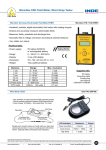
Warmbier Model PGT120, Part No. 7100.PGT120
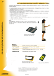
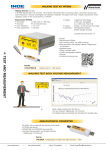
The personnel Grounding Tester PGT 120 is a wrist strap and footwear tester for access control of
ESD protected Areas (EPA). Used for compliance with the ANSI ESD S20.20 para 6.1.3.2
‘Compliance Verification Plan’.
Features:
• Simultaneous testing of wrist strap, right and left shoe
• Separate measurement of right and left foot
• LEDs display different test results
• Test result is indicated with audible and
visual LED indications
• Can be used on becnh tops or as a wall mounted unit
(Wall mounting requires an additional wall mounting plate
• Battery powered with low-battery indication
• Optional AC Adaptor is available.
• Lower limit disabling is possible.
Specifications:
• Floor Plates:
• Unit dimensions:
• Foot Plate size:
• Battery:
• LEDs:
• Alarm:
• External Power:
Aluminum
150 x 200 x 65mm
350 x 500 x 8 mm
9 volt
(6) Low, High and Pass
Internal buzzer
AC/DC (optional)
Footwear electrode
for separate shoe testing
(350 x 500 x 8 mm)
Limit values and measure mode:
Wrist strap / coil cord
Footwear worn on metal plate
(values for each shoe)
Footwear in series
Measuring range / Test voltage
750 k - 35 M
(100 k *) - 35 M
or (100 k *) - 70 M
* lower limit can be disabled
140 M or 70 M
(both shoes in series)
100V/DC
changeable to 50V or 30V
Test voltage
(without load)
Scope of Supply
(Model PGT120-WK Test Kit,
P/N 7100.PGT120-P)
- Main PGT120 Combo Tester
- Footwear electrode
- Wall Mounting Plate
- 9 Volt Battery
- User Manual & cal. certificate
Scope of Supply
(Model PGT120 Tester,
P/N 7100.PGT120)
- Main PGT120 Combo Tester
- Footwear electrode
- 9 Volt Battery
- User Manual & cal. certificate
Standard
IEC 61340-5-1
IEC 61340-5-1
--IEC 61340-5-1
Accessories
(Optional)
- P/N: 7100.PGT120.WK,
Wall mounting plate
- P/N: 7100.PGT120.SM,
Mat for footwear electrode
with yellow edges
shown trademarks are property of their respective owners.
While the information contained herein in, has been carefully compiled to the best of our knowledge, nothing is intended as representation and warranty on our part; and no statement shall be construed as recommendation to infringe any of existing
patents. We accept no liability of whatsoever for any faults and errors in the information contained herein. Contents of this catalogue and specifications of the products, are subject to change without notice due to continuous improvements.
www.indeonline.in
Cell: 09316134502
Fax: 0172-4640415
Email: [email protected]
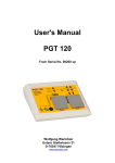
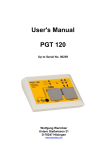
User's Manual
PGT 120
From Serial No. 00260 up
Wolfgang Warmbier
Untere Gießwiesen 21
D-78247 Hilzingen
www.warmbier.com
PGT 120 User's manual (from SN: 00260 up)
Part No. 7100.PGT120
_
Table of contents
INTRODUCTION....................................................................................................................3
INSTALLATION .....................................................................................................................4
OPERATION..........................................................................................................................5
Wrist strap test.....................................................................................................................5
Coil cord test ........................................................................................................................5
Footwear test (single shoe)................................................................................................5
Wrist strap and footwear test..............................................................................................6
Footwear in series ...............................................................................................................6
CONFIGURATION .................................................................................................................8
CONNECTORS......................................................................................................................9
WALL MOUNTING INSTRUCTIONS ...................................................................................10
SPECIFICATIONS ...............................................................................................................11
PICTURES...........................................................................................................................12
Page 2 of 13
V0108
PGT 120 User's manual (from SN: 00260 up)
Part No. 7100.PGT120
_
Introduction
The Personnel Grounding Tester PGT120 is an electronic test instrument for checking
personnel grounding systems such as wrist straps, coil cords and footwear. The PGT120 is
suitable for compliance verification of the above products, according to the IEC 61340-5-1
Edition 1.0 (2007-08) or ANSI/ESD S 20.20 – 2007 (2007-03).
•
The unit operates with 3 independent measuring circuits for the left shoe, the right shoe
and the wrist strap. This makes it possible to measure all the values at the same time
•
It is possible to enable or disable separately the measuring circuits.
•
The order of tests is random.
•
Footwear measurement can be configured to measure in series with hands free for
passenger gates.
•
Visual and audible test results and a dry relay contact for door opener
•
Use the optionally available "Calibration Unit " Part No. 7100.PGT120.CU to check the
unit Hi and Lo limit values
Page 3 of 13
V0108
PGT 120 User's manual (from SN: 00260 up)
Part No. 7100.PGT120
_
Installation
The Unit is for desktop or wall mounting. The optionally available wall mounting frame (Part
No. 7100.PGT100.101) can be used to fix the unit to a wall.
The power is either supplied by a 9V battery or by a power supply. Insert the batteries by
opening the battery compartment flap on the bottom side of the unit. Take care of the proper
polarity. Close the battery compartment flap again.
It is strongly recommended to remove old or empty batteries to avoid battery
leakage.
For heavy use or footwear in series mode, we recommend using the external power supply.
Use only an original power supply connected to the "AC12V" socket on the rear. On plugging
in external power, the internal battery is disconnected.
The battery should be removed to avoid wear out.
Do not connect any conducting articles with PGT120 except original accessories (power
supply, battery and foot wear electrode) and the door opener.
Connect the foot electrode with the coloured marked plugs to the back of the unit for
footwear test.
Page 4 of 13
V0108
PGT 120 User's manual (from SN: 00260 up)
Part No. 7100.PGT120
_
Operation
This tester has no power switch. Pressing an electrode or activating "footwear in series"
activates the electrical circuit.
The measuring voltage is preset to 100V. Use the DIP switches 4+5 to adjust the voltage to
either 30V or 50V.
Refer to the DIP switch configuration table on page 8!
Wrist strap test
► Settings:
Only wrist strap or OR is activated (DIP switch 1+2)
Put on the wrist strap and connect it via a coil cord to the snap or to the socket on the left
side of the unit.
Press the left electrode and keep it pressed. A peep signal indicates the start of
measurement. After a short measuring time the result is displayed.
OK
Hi-Fail
Lo-Fail
Green LED flashes
Red LED flashes,
audible signal
Red LED flashes,
audible signal
The measured value is o.k.
Above the resistance upper limit
Below the resistance lower limit
(not applicable if lower limit is disabled)
Release the electrode.
Coil cord test
► Settings:
Only wrist strap or OR is activated (DIP switch 1+2)
To check only the coil cord, connect the coil cord to the 3mm snap located inside the wrist
strap symbol and to the 10mm snap or socket on the left side of the unit.
Press the left electrode and keep it pressed. A peep signal indicates the start of the
measurement. After a short measuring time the result is displayed.
OK
Hi-Fail
Lo-Fail
Green LED flashes
Red LED flashes,
audible signal
Red LED flashes,
audible signal
The measured value is o.k.
Above the resistance upper limit
Below the resistance lower limit
(not applicable if lower limit is disabled)
Release the electrode.
Footwear test (single shoe)
► Settings:
Only footwear or OR is activated (DIP switch 1+2)
Page 5 of 13
V0108
PGT 120 User's manual (from SN: 00260 up)
Part No. 7100.PGT120
_
Stand on the foot electrode, then press the right electrode and keep it pressed. A peep
signal indicates the start of measurement. After a short measuring time the result is
displayed.
OK
Hi-Fail
right
Hi-Fail
left
Lo-Fail
right
Lo-Fail
left
Green LED flashes
Red LED flashes,
audible signal
Red LED flashes,
audible signal
Red LED flashes,
audible signal
Red LED flashes,
audible signal
The measured values of both shoes are o.k.
Right shoe above the resistance upper limit
Left shoe above the resistance upper limit
Right shoe below the resistance lower limit
(not applicable if lower limit is disabled)
Left shoe below the resistance lower limit
(not applicable if lower limit is disabled)
Release the electrode.
Wrist strap and footwear test
► Settings:
AND function is activated (DIP switch1+2)
Put on the wrist strap and connect it via a coil cord to the snap or socket on the left side of
the unit.
Stand on the foot electrode, then press one electrode and keep it pressed. A peep signal
indicates the start of measurement. After a short measuring time the result is displayed.
OK
Hi-Fail
Lo-Fail
Green LED flashes
Red LED flashes,
audible signal
Red LED flashes,
audible signal
All measured values are o.k.
Above the resistance upper limit
Below the resistance lower limit
(not applicable if lower limit is disabled)
Release the electrode.
The OK signal only appears when all measured values are within the limits.
Footwear in series
► Settings:
Footwear in series activated (DIP switch 6)
The footwear test can be accomplished hands free, without touching a electrode. This is
useful in combination with passenger handling gates. The resistance is measured between
the two shoes. This mode cannot directly indicate the faulty shoe. Press the Shoe electrode
on the instrument to identify it.
Page 6 of 13
V0108
PGT 120 User's manual (from SN: 00260 up)
Part No. 7100.PGT120
_
Stand with both feet onto the foot electrode. If the shoes are dissipative the measurement
starts automatically with a peep signal. After a short measuring time the result is displayed
and the connected gate will open.
OK
Hi-Fail
Lo-Fail
Green LED flashes
Red LED flashes,
audible signal
Rote LED flashes,
audible signal
The measurement of the footwear in series is o.k.
Above the resistance upper limit for series connection
Below the resistance lower limit
(not applicable if lower limit is disabled)
You can step of the foot electrode.
Even if footwear in series is active, you can perform a test according chapter 0 to chapter 0
by pressing a electrode, for example to identify a bad shoe.
Page 7 of 13
V0108
PGT 120 User's manual (from SN: 00260 up)
Part No. 7100.PGT120
_
Configuration
The unit can be configured with the DIP switches on the rear according to the table below.
Standard settings are marked bold.
Switch 1
Switch 2
OFF
OFF
"OR" (wrist strap or footwear test)
ON
OFF
Only footwear test
OFF
ON
Only wrist strap test
ON
ON
"AND" (wrist strap and footwear test)
Switch 3
Test mode
Footwear upper limit
OFF
35 MΩ for single shoe / 70 MΩ for series
ON
70 MΩ
Ω for single shoe / 140 MΩ
Ω for series
Switch 4
Switch 5
OFF
OFF
30 V
OFF
ON
50 V
ON
ON
100 V
Switch 6
Test voltage
Footwear test mode
OFF
test according to switch 1 + 2
ON
footwear in series active
Switch 7
Lower limit
OFF
Lower limit disabled
ON
Lower limit enabled
Switch 8
Door opener
OFF
inactive
ON
active
Page 8 of 13
V0108
PGT 120 User's manual (from SN: 00260 up)
Part No. 7100.PGT120
_
Connectors
The connectors for the power supply, the foot electrode and the door opener are located on
the rear side of the unit. Use a "RJ12" western modular plug to connect the dry contact of
the door opener.
The door opener relay is triggered and stays on for 3 seconds when the test result indicates
OK.
This function must be enabled with DIP switch 8.
Normally Open
Normally Closed
Pin 3,4
Pin 2,3
123456
Contact function
1 2 3 4 5 6
Connector view
Door Opener
Page 9 of 13
V0108
PGT 120 User's manual (from SN: 00260 up)
Part No. 7100.PGT120
_
Wall mounting instructions
(Part No. 7100.PGT100.101)
Fix the wall mounting plate with the supplied dowels and screws and stick the self-adhesive
Velcro tapes according to the picture.
1. The surface of the plate and the bottom side of the PGT120 have to be clean, dry and
free of grease.
2. Remove protecting foil of the velcro tapes and do not touch the sticky side.
3. Apply the velcro tapes according to the picture onto the mounting plate.
4. Remove the second protecting foil of the velcro tapes and press the PGT120 against
them.
5. After 24 Hour curing time the PGT120 can be removed from the wall mounting plate
Before removing the unit, please unplug all wires.
Hold the unit on both sides and pull it forwards. To fix it again, press it back onto the velcro
tapes.
Wall mounting plate
ca. 10mm
velcro tape
Page 10 of 13
V0108
PGT 120 User's manual (from SN: 00260 up)
Part No. 7100.PGT120
_
Specifications
Operating voltage:
9V E 6F22 battery
external power supply 230V / 50Hz
Operating conditions:
15 ... 40°C
up to 75% relative humidity,
non condensing
Storage conditions:
-10 ... 60°C
up to 85% relative humidity,
non condensing
Connectors:
Wrist strap
10mm snap, 4mm snap, 4mm socket
Foot electrode
2 sockets 4mm
Door opener
Western socket 6 pin RJ-12
external 12VAC power supply (Use only for the original power
supply supplied with the instrument)
Measuring ranges:
Wrist strap
750kΩ ...
(selectable)
Footwear - each shoe
100kΩ ... 70MΩ (0Ω ... 70MΩ)
100kΩ ... 35MΩ (0Ω ... 35MΩ)
200kΩ ...140MΩ (0Ω ... 140MΩ)
(200kΩ ... 70MΩ) (0Ω ... 70MΩ)
(Hands-free-Mode)
± 10%
Footwear in series
Tolerance
35MΩ (0Ω ...
Test voltage:
open circuit voltage
30V ± 10%
50V ± 10%
100V ± 10%
Signals:
Green LED
“OK”
Rote LED’s
and buzzer
“Hi-Fail“ or ”Lo-Fail”
Door opener
Dry contact “OK“
Door opener time
3 seconds
max. voltage
60V
max. current
2A
max. power
50 VA
Contact ratings:
Operating modes:
Single test ”OR“
Double test "AND"
Only wrist strap test
Only footwear test
Hands-free-Mode
Weight:
app. 500g
Dimensions:
150 x 200 x 63 mm
Serial number:
On the side of the unit
35MΩ)
Complies with CE
Page 11 of 13
V0108
male snap 3mm
LED
"below low limit"
connections for
wrist strap test
Personnel
Grounding
Tester
Page 12 of 13
Press
electrode for
wrist strap test
Lo-Fail
Hi-Fail
OK
Press
electrode for
footwear test
LED
"measured value
in the limit"
LED
"below low limit"
LED
"upper limit exceeded"
LED
"upper limit exceeded"
PGT 120
footwear test
wrist strap test
PGT 120 User's manual (from SN: 00260 up)
Part No. 7100.PGT120
_
Pictures
V0108
Door opener
socket for
door opener
AC 12 V
socket for
external
power supply
door opener
low limits
series
voltage
high limit
mode
Page 13 of 13
Dip-Switch
87654321
OFF
ON
sockets for
foot electrode
PGT 120 User's manual (from SN: 00260 up)
Part No. 7100.PGT120
_
V0108