1
US008292493B2
(12) Unlted States Patent
(10) Patent No.:
Mooring
(45) Date of Patent:
(54) MODULAR MOVEMENT THAT IS FULLY
2 *
,
gne
9/1990
INTERCHANGEABLE IN OTHER PORTABLE
DEVICES
5,005,161 A
5,392,261 A
5,657,298 A
4/1991 Boilen
2/1995 Hsu
8/1997 Choay
5,943,302 A
8/1999
-
-
'
(
6,431,746 B1
)
6,525,997 B1
_
(73)
Ass1gnee: Wimm Labs, Inc., Los Altos, CA (US)
(*)
Notice:
Subject to any disclaimer, the term of this
patent is extended 01‘ adjusted under 35
U'S'C' 154(1)) by 0 days‘
DE
Filed:
(65)
2/2003 Narayanaswami et a1.
3/2003 Ng
4/2003 16011 et 31,
C t'
d
( on lnue )
FOREIGN PATENT DOCUMENTS
29513038 U1 11/1995
OTHER PUBLICATIONS
_
_
Palm Wrist Watch :: palminfocenter.c0n1/vieWist0ry.asp?ID:7992;
Sep‘ 20, 20124
Jul. 21, 2011
Related US. Application Data
Division of application No. 12/024,067, ?led on Jan.
31, 2008.
(51) Int. Cl.
(Continued)
Primary Examiner i Sean Kayes
(74) Attorney, Age/1!, 01’ Firm * Convergent LaW Group
LLP
(57)
G043 23/00
8/2002 Fanshaw
lujo
(Continued)
Prior Publication Data
US 2011/0176395 A1
368/283
...................... ..
6,549,791 B1
Mar. 29, 2011
_
0
Proellochs .................. .. 368/282
6,527,436 B1
(21) Appl. No.: 13/074,197
(52)
(58)
immilet a1~
,
4,958,279 A *
(75) Inventor. lijlg'ld J. Mooring, Los Altos H1lls, CA
(62)
Oct. 23, 2012
FUNCTIONAL STANDALONE AND
.
(22)
US 8,292,493 B2
(200601)
ABSTRACT
A method for manufacturing an interchangeable movement
US. Cl. ......................... .. 368/276; 368/88; 368/281
Field Of Classi?cation Search ................ .. 368/276,
includes assembling pans into a movement subassembly’
such that the subassembly is a complete Working mechanism;
368/88, 281
See application ?le fOr complete Search history-
enclosing the subassembly in a body; integrating a glass With
the body, Wherein the body comprises a single shell With only
_
References Clted
(56)
us PATENT DOCUMENTS
an opening that receives the glass, sealing the glass and the
single shell to enclose the body, thereby creating a Water
resistant modular movement; and Wherein the modular move
ment is insertable into a case of a portable device having a
1,289,155 A
12/ 1918 Goal
receptacle for removably receiving the modular movement
1,462,076 A
2,665,542 A
3 994 124 A
7/1923 SP1r0
1/1954 Sheldon
11/1976 Fujita
Without tools and in a manner Where the glass of the modular
- movement 1s v1s1ble through the case When the modular
4,167,850 A *
9/1979
4,264,969 A
4/1981 Walker et 31.
Schneider ................... .. 368/282
4,462,697 A
7/1984 Thompson
movement is insened
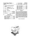
6 Claims, 8 Drawing Sheets
18 Crystal
Faceplate 302 >
Recepticle 22
Faceplate
US 8,292,493 B2
Page 2
US. PATENT DOCUMENTS
6,556,222 B1
4/2003 Narayanaswami
6,570,823 B1
5/2003 Gilomen
6,720,860 B1
4/2004 Narayanaswami
6,795,377 B2
9/2004 Gorden
7,081,905 B1
7/2006 Raghunath
7,193,606 B2
3/2007 Barnett et a1.
7,286,063 B2
10/2007 Gauthey et al.
7,682,070 B2*
3/2010
7,946,758 B2
5/2011 Mooring
2003/0151982
2004/0120224
2006/0018202
2006/0233053
2007/0189127
2007/0253290
2008/0276168
2009/0036175
A1
A1
A1
A1
A1
A1
A1
A1
Burton ........................ .. 368/294
8/2003 Brewer et al.
6/2004 Meylan
1/2006
10/2006
8/2007
11/2007
11/2008
Girardin et al.
Klein
Pollak
Aire
Mans?eldet al.
2/2009 Brandenburg et al.
FOREIGN PATENT DOCUMENTS
FR
FR
GB
GB
WO
2735664
2791150
2183063
2399253
9813734
A1
B1
A
A
A1
12/1996
6/2001
5/1987
9/2004
4/1998
“W100 wrist-watch mobile phone”, <http://www.giZmag.com/
gol7797f>, Aug. 15,2007.
“iCool M700 W100 G100 Touch Screen Wrist Watch Cell Phones”,
<http://www.ic-mall.com?cool-m700-w100-g100-touch-screen
wrist-watch-cell-phones-p-1973.htm l> Jan. 1, 2006.
“Touchscreen Cell PhonefPDA Wristwatch”, <http://www.
thinkgeek.comfgadgets/cellphone/9c9d/> Feb. 28, 2008.
“Abacus WristPDA: a Watch Goes Where no PDA Can Go,” <http://
www.theinquirer.netfen/
inquirerfnews/2006f04/30fabacus
wristpda-a-watch-goes-where-no-pda-can-go> Feb. 28, 2008.
Wrist Phone M500 Ships this WeeK, <http://Images.google.com/
Imgres?Imgurl : . . :http: I/www.slashphone.com/medlaldata/ 800/
M500 .jpg&imgrefurl :http://cell-reviews.blogspot.comf2007i
05i01iarchive. May 31, 2007.
http://www.modumobile.com/ moduimake new connections, pp.
1-3, Jan. 1,2008.
Youichi Horry et al, A Passive-Stye Butonless Mobile Terminal,
IEEE Transactions on Consumer Electronics, Aug. 2003, p. 530, vol.
49, No. 3.
PCT International Search Report and Written Opinion of the Inter
national Searching Authority, issued Mar. 3, 2009, application No.
PCT/US2009/030777.
Supplementary Extended European Search Report (EESR) of the
European Patent Of?ce, issued Jun. 28, 2011, application No. PCT/
US2009/030777.
Cellwatch M500 User Manual, <mymobilewatch.com>, May 31,
OTHER PUBLICATIONS
Apple User ManualiiPhone 3 giJul. 30, 2007.
2007.
* cited by examiner
US. Patent
0a. 23, 2012
Sheet 1 of8
US 8,292,493 B2
m
Modular
/ — Movement
12a
Crystal
18
e 22
Receptacie %
22
\
1_(_)
Modular
Movement
12b
Body _
16
Movement
Subassembly
20
FIG. 1B
US. Patent
0a. 23, 2012
Sheet 2 of8
FIG. 1C
US 8,292,493 B2
US. Patent
Oct. 23, 2012
Sheet 3 of8
US 8,292,493 B2
Assemble parts into a movement subassembly, such
that the subassembly is a complete working
mechanism
200
Enclose the subassembly in the body
202
Integrate the crystal with the body, thereby creating
the modular movement
204
Require the cases of portable devices to have a
receptacle for removably receiving the modular
movement without tools and in a manner where the
crystal of the modular movement is visible through the
case when the modular movement is inserted
206
FIG. 2
US. Patent
0a. 23, 2012
Sheet 4 of8
US 8,292,493 B2
US. Patent
0a. 23, 2012
Sheet 5 of8
US 8,292,493 B2
dMouvlemanrt
FIG.5
US. Patent
Oct. 23, 2012
Sheet 6 0f 8
US 8,292,493 B2
Computer @Q
Power
Communications
Manager 608
Interface 610
vonage
WlFi 640
Controller
636
Cellular 642
Charging
Bluetooth 644
Controller
638
Passive RFlD 646
A
V
Processors 602
MlCl'O-
DSP
processor *
Memories 604
RAM
622
614
616
Clock
GPS
Non
Volatile
(MBMS)
618
Memory
620
/
PCB Q/
504
626
i
A
H05 606
Sensors 612
Display
MEMS
Controller
630
Accelerometer
648
Audio
Sensor 1
Chip
63
2
Sensor n
Touch
Controller 634
FIG. 6
US. Patent
0a. 23, 2012
Sheet 7 of8
US 8,292,493 B2
US. Patent
0a. 23, 2012
Sheet 8 of8
US 8,292,493 B2
$83383
E62
US 8,292,493 B2
1
2
MODULAR MOVEMENT THAT IS FULLY
FUNCTIONAL STANDALONE AND
INTERCHANGEABLE IN OTHER PORTABLE
DEVICES
movement begins With a raW movement or ebauche, Which
refers to an incomplete Watch movement that is sold as a set of
loose parts, comprising a main plate, bridges, a train, a Wind
ing and setting mechanism and a regulator. The timing sys
tem, the escapement, mainspring, dial, and hands, hoWever,
CROSS-REFERENCE TO RELATED
APPLICATIONS
are not usually parts of the “ebauche”.
Very feW Watch manufacturers are capable of producing
the parts necessary for ébauches, movements, and the cases to
This application is a Divisional application of US. patent
application Ser. No. 12/024,067, ?led Jan. 31, 2008, and is
support the production and assembly of ?nished Watches.
Instead, most Watch companies purchase complete move
incorporated by reference.
ments from a supplier, such as ETA, ?t the movements With
dials and hands, and then encase the movements Within in
house or contractor-supplied cases. Some Watch companies
BACKGROUND OF THE INVENTION
may purchase ebauches from a supplier, ?nish (polish and
A typical WristWatch usually includes the following essen
decorate) the parts, optionally modify parts of the movement
tial parts: a movement housed Within a case; a piece of glass
attached to an opening in the top of the case that covers the top
face of the movement; and a case back enclosing the move
ment Within an opening in the back of the case. The move
ment is the completed, ?nished inner mechanism contained
inside the Watch, not including the case or dial, Which is
and/or add custom components, and assemble the parts to
create a higher-quality or custom movement.
20
assembly, and ?nally, case closure. During case ?tting, the
responsible for measuring the passage of time (and optionally
other information such as date, month and day).
Movements may be entirely mechanical, entirely elec
tronic (potentially With no moving parts), or a blend of the
25
tWo. A mechanical Watch is a Watch that uses a non-electric
mechanism to measure the passage of time. They are driven
by a spring (called a mainspring) Which must be Wound
periodically, and releases the energy to turn the clock’s
Wheels as it unWinds. They keep time With a balance Wheel,
30
Which oscillates back and forth at a constant rate. Mechanical
movements may be automatic (self-Winding) or manual
(manual Winding mechanism).
35
Instead, the companies typically purchase electronic move
40
BRIEF SUMMARY OF THE INVENTION
One aspect of the exemplary embodiment provides a
method for manufacturing an interchangeable movement.
Aspects of the exemplary embodiment include assembling
45
parts into a movement subassembly, such that the subassem
bly is a complete Working mechanism; enclosing the subas
sembly in a body; integrating a glass With the body, Wherein
the body comprises a single shell With only an opening that
receives the glass, sealing the glass and the single shell to
available type of electronic Watch referred to as a “smart
Watch” is capable of Wireless connectivity via PM broadcast
ing to provide consumers access to neWs, Weather, sports,
stocks, instant messenger, e-mail, and horoscopes on a liquid
tronic movements is similar in that very feW companies make
all the parts necessary to build a completed electronic Watch.
ments from suppliers and assemble electronic movements
into the cases to complete the Watch similar to the above.
ing rotor mechanism) or battery poWered. The majority of
Watches made today are equipped With electronic movements
that feature an analog time display having rotating hands on a
face or dial. Some Watches may have both analog and digital
time readouts for simultaneous display of different informa
tion.
Other Watches equipped With electronic movements may
include digital displays and small computers that are used in
many types of electronic devices. For example, a currently
Watch movement is ?tted into the case tightly so that it does
not move, and in some cases, may be physically attached to
the case With screWs. After ?tting, the case is enclosed With a
case back for proper dust and Water resistance. Typically,
Watch companies take great care in hoW the case back is
a?ixed to the case because this assembly point can be critical
for the Water tightness of a Watch. For example, one method
for achieving Water resistance is to use gaskets betWeen the
case and case back to form a seal, used in conjunction With a
sealant applied on the case to help keep Water out. Some case
backs may be screWed in, or onto, the case.
The vertical Watchmaking manufacturing market for elec
An example type of electronic movement is a quartz move
ment used in quartz Watches that utilizes frequency of vibra
tions of a quartz crystal to accurately regulate the operation of
the Watch. Quartz movements may be automatic (a self-Wind
The ?nal steps of the process is case ?tting in Which the
movement is ?tted inside the case, Which may require further
50
enclose the body, thereby creating a Water resistant modular
crystal display (LCD). The type of components found inside
movement; and Wherein the modular movement is insertable
the case of a smart Watch may include a speaker, a printed
circuit board (PCB), a processor, a memory, a radio receiver
into a case of a portable device having a receptacle for remov
chip, a rechargeable battery, and an inductive charging coil.
The Watch may be recharged by placing the Watch in a Watch
stand, and plugging the Watch stand into the Wall. When a coil
55
prising: a modular movement having a body housing a plu
rality of layers, including: a top layer of glass, a movement
attached to the contact surface on the back of the Watch comes
in contact With a charging plate on the Watch stand, the smart
Watch battery is charged through induction.
Although there may be some differences betWeen the pro
subassembly for displaying information, including time,
60
ments are assembled as a collection of parts in What can be
characterized as a vertical Watchmaking manufacturing pro
Consider by Way of example, the process used to manufac
ture a mechanical Watch movement. A mechanical Watch
Wherein the modular movement includes all parts necessary
for poWer and operation, including the displaying of the infor
mation, and Wherein the body housing comprises a single
shell With only an opening that receives the top layer of glass,
the top layer of glass and the single shell being sealed to
cesses used to manufacture a mechanical movement and an
electronic computer-based movement, both types of move
cess.
ably receiving the modular movement Without tools and in a
manner Where the glass of the modular movement is visible
through the case When the modular movement is inserted.
A further exemplary embodiment discloses a system com
65
enclose the body housing, such that the modular movement is
Water resistant and fully functional standalone; and a case, the
case including a receptacle for removably receiving the
US 8,292,493 B2
3
4
modular movement Without need for a tool, such that the
modular movement is user-interchangeable With another case
Watches and movements are constructed today Would cause
further problems for the consumer. For example, if a con
sumer removed a mechanical movement from a completed
of another portable device.
Watch, the fully functional movement Would include hands
and dials. HoWever, once the movement is removed from the
case and the attached glass, the hands and dials of the move
BRIEF DESCRIPTION OF SEVERAL VIEWS OF
THE DRAWINGS
ment Would be unprotected and could easily be damaged by
handling. In this regard, since With convention Watches it is
FIGS. 1A-1C are block diagrams illustrating exemplary
embodiments of a portable device having a modular move
the Watch that is Water resistant or Waterproof, removing the
ment.
movement from the Watch may expose the movement to
moisture, for Which the movement Would have little if no
FIG. 2 is a How chart of a process for manufacturing an
protection.
interchangeable modular movement.
The exemplary embodiment of the present invention pro
vides an improved movement and method of manufacturing
FIG. 3 is another diagram illustrating the exemplary
embodiment of the receptacle formed in the rear of the case.
thereof that enables consumers to change the movement of a
portable device, such as a Watch. No tools or disassembly/
assembly of either the portable device or the movement are
necessary; and the movement itself is modular and durable in
construction such that the movement is fully-functional stan
FIGS. 4A and 4B are diagrams illustrating the modular
movement inserted into the receptacle of the case.
FIG. 5 is a diagram of an exploded vieW of the modular
movement and components thereof When implemented as a
computer-based electronic modular movement according to
one exemplary embodiment.
FIG. 6 is a block diagram illustrating computer compo
nents on the PCB comprising the modular movement accord
ing to an exemplary embodiment.
20
easily user-interchangeable With other portable devices.
FIGS. 1A-1C are block diagrams illustrating exemplary
FIG. 7 is a diagram illustrating exemplary types of portable
device form factors that could be used With modular move
25
FIG. 8 is a diagram illustrating several vieWs of an exem
plary user interface that may be displayed on the modular
modular movement 12 When refereed to collectively) are
provided that can be removably inserted Within a case 14 of
movement.
30
the portable device 10. In the exemplary embodiments shoWn,
the portable device 10 comprises a Watch although the bands
are not shoWn, but the portable device 10 may represent other
types of devices, as described beloW.
According to the exemplary embodiments, the modular
35
movement 12 includes a body 16 that houses a plurality of
DETAILED DESCRIPTION OF THE INVENTION
The present invention relates to a modular movement that
is both fully functional standalone as Well as interchangeable
layers, including an integrated top layer of glass 18, and a
movement subassembly 20, for displaying information,
art to make and use the invention and is provided in the
context of a patent application and its requirements. Various
modi?cations to the preferred embodiments and the generic
principles and features described herein Will be readily appar
including time. FIG. 1B is a diagram of modular movement
12b shoWing a semitransparent body 16 for convenience so
40
that subassembly 20 can be seen through case 16.
As used herein, the term “modular” means that the body 16
of the modular movement 12 includes all parts necessary for
operation and poWer of the modular movement 12. Thus, the
ent to those skilled in the art. Thus, the present invention is not
intended to be limited to the embodiments shoWn, but is to be
accorded the Widest scope consistent With the principles and
features described herein.
Whether a Watch utiliZes a mechanical or electronic move
embodiments of a portable device 10 having a modular move
ment Where like components have like numerals have like
reference numerals. According to the exemplary embodi
ments, modular movements 12a, 12b and 120 (hereinafter
ment and receptacle.
in other portable devices, such as Watches. The folloWing
description is presented to enable one of ordinary skill in the
dalone and therefore retains its functionality after removal
from the portable device. The modular movement is also
modular movement 12 of the exemplary embodiment is fully
45
functional in a standalone state. HoWever, according to the
exemplary embodiment, the case 14 of the portable device 10
includes a receptacle 22 for removably receiving the modular
ment, most conventional Watches have been designed so that
consumers can change the straps or bands of a Watch and even
interchange the straps betWeen different Watches4either for
movement 12 Without need for a tool, such that the modular
aesthetic or functional reasons. For example, a consumer may
movement 12 can be either used With the case 14 of the
Wish to change betWeen a casual and a formal strap, change
betWeen different color straps, and/or change betWeen a non
50
cases of other portable devices having the same or similar
types of receptacles.
Waterproof and a Waterproof strap, for instance.
One aspect of the present invention is the recognition that
due to the history of Watchmaking and the resulting vertical
Watchmaking manufacturing process, conventional Watches
portable device 10 and/or is user interchangeable With the
55
have not been designed so that consumers can readily change
the movement of a Watch. That is, due to current construction
techniques, the manner in Which movements are a?ixed
When the modular movement 12 is used in a portable
device 10, such as a Watch, the glass 18 of the module of
movement 12 becomes the glass 18 of the portable device.
The glass 18 may include any type of transparent or semi
transparent material layer on a top surface of the modular
movement 12, including sapphire, crystal, plexiglass, and the
Within the case and/or the manner in Which the case back is
like.
attached to the case, tools and some amount of skill Would be 60
In one embodiment, the body 16 may be constructed to
provide the modular movement 12 With a degree of Water
required to remove a movement. In most instances, some
resistance and dust protection. For example, the body 16 may
disassembly of the movement may be even necessary to
be a single shell except for an opening for the glass 18 and
once the glass 18 is in place, the glass 18 may by sealed With
remove the movement from the case, thereby ensuring that
the movement Will no be longer fully functional after removal
Without repair and reassembly.
Furthermore, even assuming the consumer succeeded at
removing a movement from a case, the manner in Which
65
the body 16 using traditional Waterproo?ng methods. In
another embodiment, the body 16 may be assembled in sepa
rate pieces but then sealed once assembled.
US 8,292,493 B2
6
5
Providing a modular movement 12 having an enclosed and
electronic movement may include a computer-based move
self-contained body 16 including the glass 18 is in contrast to
traditional Watchmaking methods in Which I) the parts of the
ment With a touchscreen or LCD display and battery, for
instance.
FIG. 2 is a How chart illustrating a process for manufactur
ing an interchangeable modular movement 12. The process
movement are not integrated into a body, and 2) the Watch
glass is typically a?ixed to the Watchcase, rather than to the
Watch movement.
may begin by assembling parts into the movement subassem
bly 20, such that the movement subassembly 20 is a complete
In one exemplary embodiment, the modular movement 12
and the receptacle 22 in the case 14 are made industry stan
dard siZes, such that different modular movements 12 manu
factured and sold by a one set of manufacturers ?t Within the
receptacles of different cases manufactured and sold by
Working mechanism (block 200). The movement subassem
bly 20 is then enclosed in the body 16 (block 202); and the
glass 18 is integrated With the body 16, thereby creating the
modular movement 12 (block 204). In one exemplary
embodiment, the modular movement 12 may be provided
another set of manufacturers, for example.
FIG. 1A shoWs an embodiment Where the receptacle 22 is
modularmovement 12a is inserted into the front of the case 14
With a standard siZe and shape so that different modular
movements from different manufacturers have the same siZe.
through the open receptacle 22. In one embodiment, the
For example, in one embodiment, the standard siZe and shape
formed as an opening on the top or front of the case 14 and the
receptacle 22 may only extend partially through the depth of
of the modular movement 12 may be approximately 30 mm
the case body, leaving one side, i.e., the back, of the case 14
closed.
FIG. 1B shoWs another embodiment Where the receptacle
Wide, 34 mm tall, and 8 mm in depth, for example. In another
embodiment, the modular movement 12 may have a siZe and
20
22 is formed as an opening in the back of the case 14 and
Where the top or front of the case 14 includes an opening. In
should be suitable for the modular movement 12.
Another step to the process is requiring the cases 14 of
portable devices 10 to each have a receptacle 22 for remov
this embodiment, the modular movement 12b is inserted into
the case 14 from the bottom or back of the case 14, and once
inserted the glass 18 of the modular movement 12b is visible
through the opening in the top of the case 14.
Although FIGS. 1A and 1B shoW that once the modular
movement 12b is inserted into the receptacle 22, no closure is
necessary to seal the case 14 unlike With traditional Watches.
FIG. 1C is a diagram illustrating that in an alternative embodi
ment, a receptacle door 24 may be used to close the case 14
once modular movement 120 is inserted into the receptacle
25
movement 12 is inserted (block 206).
30
35
receptacle 22 may be provided With internal latching mecha
another embodiment, a mechanism may be used that pres sur
40
iZes the modular movement 12 into the receptacle 22 from the
outside of the case 14. In yet another embodiment, contacts
510 on the modular movement 12 may be provided With
springs that hold the modular movement 12 in place When
inserted.
In yet another embodiment, at least one Wall of the recep
(e.g., FIG. 1C).
45
movement 12 may be a mechanical movement or an elec
tacle 22 may be provided With one or more magnets that have
suf?cient attraction force to hold modular movement 12 in
place When inserted. A spring loaded decoupling mechanism
tronic movement. FIG. 1A may illustrate an embodiment
Where the modular movement 12a is implemented as a
mechanical movement. In this exemplary embodiment, the
subassembly 20 Within the body 16 of modular movement
latching mechanisms may be used to retain the modular
movement 12 inside the receptacle 22. For example, the
nisms such as snaps, clamps or springs, for example. In
(FIGS. 1A and 1B). But for largerportable devices, the siZe of
the portable device/case to the receptacle 22 may be larger
According to an exemplary embodiment, the modular
The receptacle 22 should be designed so that no tools are
required for modular movement 12 insertion or ejection so
that the modular movement 12 is easily user interchangeable.
According to the exemplary embodiment, several different
attached to the case 14 via a hinge.
But the term case 14 may denote the body of the portable
device 10 into Which the receptacle 22 is formed and into
Which the modular movement 12 is to be inserted. Thus, for
small portable devices 10, such as a Watch, the proportionate
siZe of the portable device/case to the receptacle 22 is small
ably receiving the modular movement 12 Without tools and in
a manner Where the glass of the modular movement 12 is open
or at least visible through the case 14 When the modular
22. In another embodiment, the receptacle door 24 may be
As used herein, the portable device 10 may include a com
bination of both the case 14 and the modular movement 12.
shape of approximately 32><32><l0 mm, for example. Thus,
any siZes ranging approximately around these dimensions
50
1211 Would include a mechanical movement comprising not
could be used to then eject the modular movement 12.
Also, in a Watch or other Wearable portable device 10
embodiments Where the back of the case 14 is open, any of the
latching mechanisms may be calibrated to account for When
only components of a traditional raW movement such as a
the case 14 is Worn and the modular movement 12 is inside the
main plate, bridges, a train, a Winding and setting mechanism
receptacle 22, the modular movement 12 may be held inside
and a regulator; but also a timing system, an escapement, a
mainspring, and a time display such as dial and hands. The
the receptacle 22 at least in part by the Wearer’s body (e. g., by
55
time display may be covered by the glass 18. The mechanical
movement of the subassembly may be automatic or manual.
The Winding and setting mechanism may include a compo
nent, such as a push-in croWn, built into the case 14 that When
pushed-in, Would engaged With a recess in the side of the
modular movement to interact With the Winding and setting
mechanism.
FIGS. 1B and 1C illustrate example embodiments Where
a Wrist).
Requiring no tools for insertion or ejection of the modular
movement 12 may be a function of both the design of the
receptacle 22 and the case 14. The design of the receptacle 22
60
and case 14 also affect hoW the inserted modular movement
12 Will be visible through the case 14.
FIG. 3 is a diagram illustrating a rear vieW of the case 14
and the receptacle 22 according to one exemplary embodi
ment. The receptacle 22 may be formed in the case 14 by a set
the modular movements 12b and 120 are implemented as an
of sideWalls 300 Whose number, shape, siZe, and depth should
electronic movement. Examples of an electronic movement 65 be substantially similar to those of the side Walls of the modu
may include a quartz movement With an analog or digital
display, and With or Without a battery. Another example of an
lar movement 12. In addition, the case 14 may be provided
With a faceplate 302 that may function to aid in retaining the
US 8,292,493 B2
7
8
modular movement 12 inside the case 14 as Well as de?nes
inserted into the body 16 and in contact With the PCB. The
Which portions of the modular movement 12 are visible
through the case.
FIGS. 4A and 4B are diagrams illustrating the modular
movement inserted into the receptacle of the case. In one
embodiment, the depth or thicknesses of the modular move
ment 12 and the case 14 may be designed to be substantially
similar, so that When the modular movement 12 is inserted,
the side of the modular movement 12 facing the open end of
contacts may be used for recharging the battery (the contacts
are both poWer and ground) and/or for serialized communi
cations. The contacts can also be used for orientation pur
poses for the user to tell Which side of the modular movement
12b is up or doWn When inserting the modular movement 12b
into the receptacle 22 of the case 14. In one embodiment, the
contacts 510 are located on a side of the modular movement
1211 that is in the receptacle 22 opening so that the portable
the receptacle 22 is coplanar With the back of the case 14 (and
the Wearer’s arm), as shoWn in FIG. 4A. As shoWn in FIG. 4B,
the glass 18 of the modular movement 12 that is open through
the faceplate 302 of the case 14 may be designed to be
device 10 as a Whole can be placed in a dock and the contacts
510 used to abut the contacts of the dock. In another embodi
ment, the contacts 510 are located on a side of the modular
movement 12b that face inWard into the receptacle 22 for
abutting With contacts in the receptacle 22. In yet another
embodiment, the contacts 510 may be located on the modular
approximately coplanar With (or slightly above or beloW) the
top of the case 14.
In some embodiments, the modular movement 12 may
have its front and back sides open in the front and rear of the
case 14. HoWever, some measure of protection may be pro
vided by con?guring the receptacle 22 so that the four side
Walls 300 of the receptacle 22 fully cover the four remaining
sides of the modular movement 12, as shoWn. Also, although
movement 12b such that the contacts 510 Wrap around at least
tWo side of the modular movement 12b to be used in both
manners.
20
shoWn into a movement subassembly 20. The movement
subassembly 20 is then inserted into the body 16 and the body
is sealed, creating the computer-based modular movement
openings for the modular movement 12 are shoWn in the front
and rear of the case 14 via the faceplate 302 and receptacle 22,
in another embodiment, the receptacle 22 may also be formed
on a side, bottom or top of the case as Well, particularly for
25
other types of portable devices 10 and form factors.
In a further embodiment, the faceplate 302 may be pro
vided in any shape desired, such as square, round, oval, tri
12b.
FIG. 6 is a block diagram illustrating computer compo
nents on the PCB comprising the modular movement 12b
according to an exemplary embodiment. In one embodiment,
the PCB 504 containing computer 600 may be implemented
angular or rectangular, for instance, and the shape of faceplate
3 02 may be different than the shape of the modular movement
During assembly, the contacts 510 are inserted into the
body 16; and the layers of components are assembled as
as a single sided or double-sided PCB. In another embodi
12. Thus, in the case of a Watch, although a square or rectan
gular modular movement 12 is inserted into a square or rect
ment, the PCB 504 may be implemented as separate PCBs
and stacked Within the movement subassembly 514.
Computer 600 may include components such as processors
angular receptacle 22 in the case 14, the modular movement
12 may be given the appearance of a round face by providing
a communications interface 610, and sensors 612. In one
the case 14 With a round faceplate 302. Similarly, in the case
of a round modular movement 12, the case may be given a
30
602, memories 604, inputs/outputs 606, poWer manager 608,
35
600 may be implemented on a single chip.
square or rectangular faceplate 302 if desired. Accordingly,
The processors 602 may include at least one microproces
sor 614, a digital signal processor (DSP), a global positioning
chip (GPS) 616, and a clock 620. Microprocessor 614 and/or
the case 14 design has no restrictions on What faceplate/
movement shape combinations that can be used. Any shaped
faceplate 302 may be applied to the case 14 for use With any
40
shaped modular movement 12 and correspondingly shaped
receptacle 22.
According to another aspect of the exemplary embodi
processes of the modular movement 12b. In one embodiment,
45
Clock 620 may be used as an internal timing device for the
computer 600. Clock 620, Which may also be referred to as a
50
ment 12 includes body 16 that houses multiple layers of
components, Which in this exemplary embodiment, may
include a plastic internal chassis 500, a rechargeable-type
battery 502, a printed circuit board (PCB) 504, a touchscreen
506, and an optional second plastic internal chassis 508 and
protective covering 512. In this embodiment, the modular
microprocessor 614 may comprise an Advanced RISC
Machine (ARM) processor or the like may be used, for
example. GPS 618 may process received signals and With or
Without microprocessor 614 determine position information
such as location, speed, direction, and time.
computer-based electronic modular movement according to
one exemplary embodiment. As shoWn, the modular move
DSP may be capable of concurrently executing multiple soft
Ware routines, including system code, to control the various
ment, the modular movement 12 is implemented as a com
puter-based electronic movement that is used to poWer the
portable devices into Which it is inserted, as described beloW.
FIG. 5 is a diagram of an exploded vieW of the modular
movement and components thereof When implemented as a
embodiment, one or more of the components of the computer
55
real-time clock or system clock, inputs to the microprocessor
614 a constant How of timing pulses for operation of the
microprocessor 614. Clock 620 may also keep track of the
time of day and makes this data available to the softWare
routines executing in microprocessor 614. In one embodi
ment, clock 620 comprises a silicon clock oscillator imple
mented using micro-electro-mechanical systems (MEMS)
movement 12 has six sides, but the side With the touchscreen
technology. In another embodiment, clock 620 may utiliZe a
is substantially all display space.
The PCB 504 may include components (described beloW)
quartZ crystal oscillator.
such as a memory and processor for executing softWare that
displays a user interface on the touchscreen 506 and that
operates the modular movement 12b; and an optional com
Memories 604 may include a random access memory
60
munications interface for receiving data remotely, Which may
be displayed and updated on the touchscreen 506.
Other components of the modular movement 12b may
include an antenna (not shoWn) that Wraps around the body 1 6
(alternatively embedded in case 14), and a set of contacts 510
65
(RAM) 622 and a nonvolatile memory 626. RAM 622 may be
used as the main memory for microprocessor 614 for support
ing execution of the softWare routines and other selective
storage functions. Non-volatile memory 626 is capable of
holding instructions and data Without poWer and may store
the softWare routines for controlling modular movement 12b
in the form of computer-readable program instructions. In
one embodiment, non-volatile memory 626 comprises ?ash
US 8,292,493 B2
10
interface 610 may also include other types of communica
tions devices (not shoWn) besides Wireless, such as serial
communications via contacts 510 and/or USB communica
memory. In alternative embodiments, non-volatile memory
626 may comprise any type of read only memory (ROM).
I/Os 606 may include a display controller 630, an audio
chip 632, and a touchscreen controller 634. Display controller
630 may access RAM 622 and transfer processed data, such
tions, for example.
as time and date and/or a user interface, to the touchscreen
MEMS accelerometer 648, and any number of optional sen
Sensors 612 may include a variety of sensors including a
506 for display. The audio chip 632 is coupled to an optional
sors 1-n. MEMS accelerometer 648 may be used to measure
speaker (not shoWn) and interfaces With microprocessor 614
information such as position, motion, tilt, shock, and vibra
tion for use by microprocessor 614. The computer 600 may
additionally include any number of optional sensors 1-n,
including environmental sensors (e.g., ambient light, tem
to provide audio capability for the modular movement 12b. In
another embodiment, the audio chip 632 may be coupled to
both a speaker and a microphone (not shoWn). In this embodi
ment, a Water resistant/proof speaker and microphone may be
perature, humidity, pressure, altitude, etc), biological sensors
(e.g., pulse, body temperature, blood pressure, body fat, etc.),
used to retain Water resistance of the modular movement 12b.
In an alternative embodiment, the modular movement 12b
and a proximity detector for detecting the proximity of
objects. In one embodiment, the proximity detector may be
implemented as an infrared data association (IRDA) proxim
ity detector. The computer 600 may display the information
measured from the sensors 612, analyZe the information by
may be implemented Without sound capability, in Which case
no audio chip 632, speaker or microphone is necessary.
In the embodiment Where the audio chip 632 is coupled to
both a speaker and microphone, the microphone may record
voice input that is ?rst processed by the audio chip and then
input to the microprocessor 614 for further processing. The
microprocessor 614 and display the analyZed information,
20
audio chip 632 may include hardWare and/or softWare that
converts analog voice into pulse code modulation (PCM) or
and/or transmit the raW or analyZed information via the com
munications interface 610. In one embodiment, not all of the
sensors 612 may be located on PCB 504.
Adaptive Differential PCM (ADPCM) digital code and vice
In a further aspect of the exemplary embodiment, the
versa, as Well as for compressing and decompressing the
modular movement 12b may include more than one battery
502 and/or the portable device 10 may include one or more
PCM orADPCM digital audio signal. In one embodiment, the
25
processed voice input may be stored for subsequent playback.
In another embodiment, the processed voice input may be
transferred to communications interface 610 for Wireless
transmission.
Touch controller 634 may interface With the touchscreen
506 to detect touches and touch locations and pass the infor
mation on to microprocessor 614 for determination of user
interactions. Another example I/O 606 may include a USB
external batteries (not shoWn). In this embodiment, the modu
30
and the percentage of battery poWer remaining in each of the
batteries. In the case of a Watch, for example, a band and case
controller (not shoWn).
PoWer manager 608 communicates With the microproces
sor 614 and coordinates poWer management for the computer
600 While the computer is draWing poWer from the battery
502 during normal operations. In one embodiment, the bat
tery 502 may comprise a rechargeable, lithium ion battery or
the like may be used, for example. The poWer manager 608
includes a voltage controller 636 and a charging controller
638 for recharging the battery 502. Voltage controller 636
may regulate battery voltage to the rest of the computer 600,
and charging controller 638 may manage appropriate voltage
levels to properly charge the battery 502. PoWer manager 608
may further include a microcontroller (not shoWn) in one
embodiment.
The communications interface 610 may include compo
nents for supporting one-Way or tWo-Way Wireless commu
nications. In one embodiment, the communications interface
35
the modular movement 12b may be built into the case of any
45
device form factors that could be used With modular move
ment 12b and receptacle 22. As shoWn exemplary types of
portable devices that may include standard receptacles 22 for
use With modular movement 12b may include a cell phone
handset 700, a carrier and strap 702, a media player 704,
50
portable speakers 706, battery dock recharger and speaker
708, a Watch 710, a media handset and cradle 712, a telephone
handset 714, and a portable charging cradle 716 for the modu
lar movement 12b. Through the use of charging cradle 716,
screen 506. HoWever, in an alternative embodiment, besides
transmitting data, the communication interface 616 could
the modular movement 12b can be recharged, even While
55
outside of the portable device 10. Thus, the exemplary
embodiment provides a module movement 12b that can be
used, operated and recharged Whether both alone and When
inserted into the portable device 10. Other example portable
intermediate poWer radio frequency (RF) communications.
The communications interface 610 may include one or more
transceiver 644 for loW-poWer communication according to
the Bluetooth protocol and the like, such as Wireless personal
area netWorks (WPANs); and passive radio-frequency iden
ti?cation (RFID) 646. Others Wireless options may include
baseband and infrared, for example. The communications
In a further aspect of the exemplary embodiment, the
receptacle 22 of the standard siZe that is designed to receive
type of portable device 10.
FIG. 7 is a diagram illustrating exemplary types of portable
streaming data, Which is displayed and updated on the touch
of a WiFi transceiver 640 for supporting communication With
a WiFi netWork, including Wireless local area netWorks
(WLAN), and WiMAX; a cellular transceiver 642 for sup
porting communication With a cellular netWork; Bluetooth
assembly may include a left strap and a right strap, and may
further include a left battery in the left strap and a right battery
in the right strap. In this embodiment, the modular movement
12b may be con?gured to selectively determine Whether to
use battery 502, the left battery, and/or the right battery, or
some combination of the three.
40
610 is for primarily receiving data remotely, including
also support voice transmission. In an exemplary embodi
ment, the communications interface 610 supports loW and
lar movement 12b may be con?gured via the softWare rou
tines and poWer manager 614 to selectively determine
Whether to draW poWer from the battery or batteries 502, the
external battery or batteries, or a combination thereof depend
ing on a variety of factors such as current operating conditions
60
devices include a bike handlebar cradle, a modem housing
(e.g., for notebook computers), an adapter to convert to a USB
dongle, jeWelry, a lanyard, clothing, a keychain and a neck
lace, for instance.
Thus, according to the exemplary embodiment, the modu
lar movements 12b made by the same or different manufac
65
turers may be interchangeable by users into various portable
devices 10 made by different manufacturers due to the stan
dard form factor designs of the modular movements and
US 8,292,493 B2
11
12
receptacles 22. Once inserted into the portable device 10, the
modular movement 12b operates and optionally poWers the
portable device 1 0. If the modular movement is equipped With
the user’ s personal information and Wireless connectivity, the
In a further embodiment, the user interface may be pro
vided With auto con?guration settings. In one auto con?gu
ration embodiment, once the modular movement 12b is
inserted into the receptacle 22 of the case 14, the modular
movement 12b may be con?gured via contacts 510 or Wire
lessly to automatically determine characteristics of the case
user may carry the modular movement 12b around Wherever
the user goes and may plug the modular movement 12b into
Whatever compliant portable devices 10 are available.
14, such as the make, model, and shape of the faceplate 302
and/or receptacle 22 opening. Using the characteristics of the
For example, consider the scenario in Which a user Wakes
up in the morning, and While shaving plugs the modular
case 14, the modular movement 12b may automatically con
movement 12b into a receptacle 22 next to the mirror. There
?gure its user interface 800 accordingly. For example, if the
after, the modular movement 12b streams stocks, Weather and
modular movement 12b detects that it is inserted into a case
the like for the user via an Internet connection made using the
RF communications interface 610. When it is time to leave for
Work, the user removes the modular movement 12b from the
receptacle 22 and inserts the modular movement 12b into his
or her Watch 710 or cell phone handset 700, and takes the
(e.g., via a corresponding set of contacts in the receptacle)
having a rectangular or square faceplate 302 that does not
overlap the glass 18 of the touchscreen 506 in any Way, then
no changes to the user interface 800 need to be made. If,
hoWever, the modular movement 12b detects that it is inserted
into a case having a round or oval faceplate 302 that overlaps
the comer of the touchscreen 506, and therefore eliminates
modular movement 12b along. In addition, if the modular
movement 12b is equipped With RFID, the modular move
ment 12b may be used for automatic payment of goods and
areas of the screen space, i.e., the comers, then the modular
services. The user may use the modular movement 12b to 20 movement 12b may automatically recon?gure the user inter
face 800 to display information only in the available areas of
carry or access his or her personal information, such as email,
contacts, voicemail, etc., stream real-time data and media,
the touchscreen 506.
and may even use the modular movement 12b in the place of
In another auto con?guration embodiment, the orientation
of user interface may automatically change in response to the
modular movement 12b detecting a change in the orientation
of the modular movement 12b.
A modular movement that is both fully functional standa
cash and credit cards.
FIG. 8 is a diagram illustrating several vieWs of an exem
plary user interface that may be displayed on the modular
25
movement 12b. In one embodiment, the user interface 800
displayed on the touchscreen 506 of the modular movement
12b may include menu items 802 and/ or an icon carousel 804.
The icon carousel 804 is a scrollable display of icons that are
laid out along an arc of the Wheel across the touchscreen 506,
30
Where only a subset of the icons (e.g., ?ve, 2 on each side of
a center position) are visible on the touchscreen 506 at a time.
The user may rotate/ scroll the icons around the icon carousel
804 to the left or right With a sWipe of the ?nger in the
35
corresponding direction along the icon carousel 804. When
the rotating icon carousel 804 stops rotating, the icon in the
center position is the currently active icon that can be selected
or activated. The user may select one of the menu items 802 or
the currently active icon With a ?nger touch or double touch.
program instructions, or a combination thereof. Software
40
ousel 804, Whichever icon is displayed in the center position
may automatically enlarge for ease of vieWing. Other
45
302, and the icon carousel 804 displayed With an analog clock
display.
50
that a button or a dial for controlling the user interface are
completely absent from both the modular movement and the
case 14, thereby simplifying user interface 800 and saving
manufacturing costs. In one embodiment, a button may be
provided on the side of the modular movement 12b, for reset
ting, but not for controlling user interface 800. In an alterna
tive embodiment, the modular movement 12b may be auto
matically reset When ?rst plugged-in to be recharged, or the
recharging cradle may be provided With a reset button.
In the embodiment Where the touchscreen 506 of the
modular movement 12 is open through the faceplate 302 of
the case 14 and is slightly beloW the top ofthe case (e.g, FIG.
4B), the UI may be designed such that the edges of the case 14
surrounding the touchscreen 506 are used as guides to the
user’s ?ngers as the user makes ?nger gestures across the
touchscreen 506.
be, for example, transmitted over a netWork. Accordingly,
many modi?cations may be made by one of ordinary skill in
the art Without departing from the spirit and scope of the
appended claims.
It should be noted that the user interface 800 has no buttons
on the modular movement 12b. Instead, the user interface 800
of the modular movement 12b is controlled entirely by the
user interacting With the touchscreen 506 through touch, such
Written according to the present invention is to be either stored
in some form of computer-readable medium such as memory
or is to be transmitted over a netWork, and is to be executed by
a processor. Consequently, a computer-readable medium is
intended to include a computer readable signal, Which may
In one embodiment, as the icons scroll around the icon car
embodiments are also shoWn in FIG. 8, such as the user
interface 800 displayed on a Watch With a round faceplate
lone and interchangeable in other portable devices, such as
Watches, has been disclosed. The present invention has been
described in accordance With the embodiments shoWn, and
one of ordinary skill in the art Will readily recogniZe that there
could be variations to the embodiments, and any variations
Would be Within the spirit and scope of the present invention.
For example, the portable device may be provided Without
communication capability and used to store a user’s personal
information, such as medical records for, instance.
In addition, the embodiments can be implemented using
hardWare, softWare, a computer readable medium containing
55
We claim:
1. A method for manufacturing an interchangeable move
ment comprising:
assembling parts into a movement subassembly, such that
the subassembly is a complete Working mechanism,
enclosing the subassembly in a body, and
integrating a glass With the body, Wherein the body com
prises a single shell With only an opening that receives
the glass,
sealing the glass and the single shell to enclose the body,
thereby creating a Water resistant modular movement;
60
inserting the modular movement into a case of a portable
device having a receptacle formed in an opening in a rear
of the case for removably receiving the modular move
ment Without tools and in a manner Where the glass of
the modular movement is visible through the case When
65
the modular movement is inserted; and
calibrating a latching mechanism of the case to account for
When the case is Worn and the modular movement is
US 8,292,493 B2
14
13
6. A system, comprising:
inserted into the receptacle, the modular movement is
held inside the receptacle at least in part by a Wearer’s
a modular movement having a body housing a plurality of
layers, including:
body.
a top layer of glass,
a movement subassembly for displaying information,
2. The method of claim 1 further comprising:
forming the receptacle in the case With a set of sideWalls
including time,
Whose number, shape, siZe, and depth are substantially
Wherein the modular movement includes all parts neces
similar to those of the modular movement; and
providing the case With a faceplate that aids in retaining the
sary for poWer and operation, including the displaying of
the information, and Wherein the body housing com
prises a single shell With only an opening that receives
modular movement inside the case and de?nes Which
portions of the front of the modular movement are vis
ible through the case.
3. The method of claim 2 Wherein the depth of the modular
the top layer of glass, the top layer of glass and the single
shell being sealed to enclose the body housing, such that
the modular movement is Water resistant and fully func
tional standalone; and
movement and the case are substantially similar so that When
the modular movement is inserted into the receptacle, one
side of the modular movement is coplanar With an open end of
the case, and Wherein the glass that is open through the
faceplate is approximately coplanar With a top of the case.
4. The method of claim 3 further comprising providing the
faceplate With a shape different from that of the modular
movement.
5. The method of claim 1 further comprising providing the
modular movement With a subassembly comprising at least
one of a mechanical movement and an electronic movement.
15
a case, the case including a receptacle formed in an opening
in a rear of the case for removably receiving the modular
movement Without need for a tool, such that the modular
movement is user-interchangeable With another case of
another portable device, Wherein the case includes a
latching mechanism that is calibrated to account for
20
When the case is Worn and the modular movement is
inserted into the receptacle, the modular movement is
held inside the receptacle at least in part by a Wearer’s
body.