Download Acoustic triggered laser device for simulating firearms
Transcript
lllllllllllllllllllllllllllllllll||||l||l|l||||l|||llllllllllllllllllllllll
US005605461A
United States Patent 1191
[11] Patent Number:
Seeton
[45]
[54]
5,605,461
Date of Patent:
Feb. 25, 1997
ACOUSTIC TRIGGERED LASER DEVICE
5,119,576
6/1992 Erming .
FOR SMULATING FIREARMS
5,194,007
5,237,773
3/1993 Marshall et a1. ........................ .. 434/21
8/1993 Claridge .
Inventor: Gary
Station,E-Tex.
Seetoll,
77840 FiI'CSidC, College
[21]
Appl. No.: 330,199
[22]
Flled‘
-
Beamhit I 10 User’s Manual, Beamhit Systems, pp. 1-47
(Ape 1994)- '
,
Primary Examiner—Richard J. Apley
Oct' 27’ 1994
Assistant Examiner—John Mulcahy
[51]
Int. Cl.6 ...................................................... .. F41G 3/26
Attorney, Agent, or Firm-Pravel, Hewitt, Kimball &
[52]
US. Cl. ......... ..
Kl‘ieger
[58]
Field of Search ................................ .. 434/19, 21, 22;
.. 434/21; 42/103
[57]
ABSTRACT
381/155, 169, 173; 372/31, 38; 42/103
A device that simulates the ?ring of a ?rearm. The device
[56]
References Cited
3,526,972
9/1970 Sumpf_
includes a piezoelectric crystal for detecting high amplitude
acoustic pulses generated when the ?ring mechanism of the
?rearm is activated. The piezoelectric crystal provides a
voltage pulse to a amplitude detecting circuit. If the pulse
3,633,285
1/1972 Sensney .
generated by the piezoelectric crystal is above a threshold
Us" PATENT DOCUMENTS
3,938,262 2/1976 Dye et al. .
3,995,376 12/ 1976 Kimble 61 vi gkilahhem ~
value, the amplitude detecting circuit causes a laser diode to
be energized. The laser diode directs a beam at the target to
4,313,272
4,313,273
2/1982 Matthews I
2/1982 Matthews et a1. _
allow the user to determine where the “shot” is ?red. The
laser d1ode1s activated for a 'su?iciently long period of time
to allow the laser spot to be v1s1ble to‘the human eye'and also
4,367,516
4,678,437
4,761,907
1,1983 Jacob _
7/1987 Scott et a1. .............................. .. 434/21
g/19g8 De Bern-Mimi '
to allow a streak to be developed 1f the ?rearm is pulled
Slightly by the user when the trigger is Phhed- The deviee is
conveniently mounted under the barrel of the ?rearm.
4,830,617
5/1989 Hancox et al. .
4,947,859
8/1990 Brewer et a1. ........................ .. 381/169
,
,
aw
I
.
.
.
.
.
43 Claims, 4 Drawing Sheets
A
j .
20
.
US. Patent
Feb. 25, 1997
Sheet 1 of 4
5,605,461
U.S. Patent
Feb. 25, 1997
Sheet 2 of 4
5,605,461
‘1
A
I
I
'|
FZ/G.
)
5/
k57
US. Patent
Feb. 25, 1997
Sheet 3 0f 4
5,605,461
5,605,461
1
2
quency of the acoustical energy generated by the ?ring
ACOUSTIC TRIGGERED LASER DEVICE
FOR SI1VIULATING FIREARMS
mechanism of a gun shifts with changes in temperature. In
addition, different ?rearms have different frequency charac
teristics, which would require that the simulation device be
modi?ed for di?erent ?rearms.
Therefore, it is desired that a ?rearm simulation device be
developed that is simple to use and that does not require
BACKGROUND OF THE INVENTION
1. Field of the Invention
The invention relates to an apparatus for simulating
modi?cation to be used with different types of ?rearms.
?rearms, and more particularly, to a device for mounting on
a ?rearm which utilizes a laser beam to simulate the ?ring
of real ammunition.
SUMMARY OF THE PRESENT INVENTION
2. Description of the Related Art
The simulation device according to the present invention
includes a means for sensing the acoustical energy devel
Various marksmanship training devices that simulate the
?ring of a ?rearm have been developed. These devices allow
oped by the hammer in a ?rearm falling on the ?ring pin.
The sensing means is preferably a piezoelectric crystal. In a
“dry” ?re situation, that is, no bullets are actually being
?red, the fall of the hammer on the ?ring pin delivers a
the owner of a ?rearm, such as a handgun or a ri?e, to
improve their shooting skills without the need for live
ammunition. Certain devices, such as the one disclosed in
U.S. Pat. No. 4,367,516, entitled “MARKSMANSHIP
higher amplitude pulse then any other action that is likely to
TRAINING DEVICE AND METHOD” by Jacob, require
the disassembly of the ?rearm and replacement with tem
befall a gun in normal practice. To sense this high amplitude
porary parts to form a device that ?res a light beam upon
activation of the trigger on the ?rearm. These devices are
20
generated by the ?ring mechanism, the piezoelectric crystal
generally difficult to use and are limited to those persons
who are familiar with the assembly and disassembly of
?rearms. In an alternative device, disclosed in U.S. Pat. No.
5,237,773, entitled “INTEGRAL LASER SIGHT, SWITCH
FOR A GUN” by Claridge, a switch is mounted on the back
of the gun handle so that it can be momentarily operated by
the thumb of the trigger hand to emit a visible laser beam.
However, this provides a poor simulation of real weapon
operation, as manual operation of the switch requires the
pulse, the piezoelectric crystal can be placed at any conve
nient location on the ?rearm. In response to the pulse
provides a high amplitude signal to a amplitude sensing
circuit, which is designed to trigger at a su?‘iciently high
25
30
user to deviate from his or her normal grip of the ?rearm.
In yet another device, described in U.S. Pat. No.3,938,
262 entitled “LASER WEAPON SIMULATOR” by Dye, et
voltage so that any other signal source would be below the
triggering threshold. If the amplitude sensing circuit pro
vides a signal indicating that a su?iciently high input voltage
has just been received, a light emitting device, which is
preferably a laser diode, is turned on for a suf?ciently long
period to allow a visible laser spot to be developed on the
target. In addition, the laser diode stays on long enough to
show a slight streak to indicate if the gun is being pulled to
one side with the pulling of the trigger, which is a common
mistake made during the ?ring of a weapon. Further, the
a1., a piezoelectric crystal mounted on the gun is used to 35 device can be used as a replacement for tracer bullets to
indicate where a bullet is being ?red. For use in tracer mode,
sense shock waves produced by the ?ring of blank car
an overvoltage circuit is included in the device to protect the
tridges. In response to the generated shock waves, the
device from the extremely high voltages generated by the
piezoelectric crystal oscillates to provide electrical energy to
piezoelectric crystal in response to the ?ring of an actual
a laser diode, which emits an infrared output pulse. The
infrared output pulse, which is invisible to the human eye, 40 bullet. One of the advantages of the device according to the
present invention is that it can be conveniently mounted on
strikes an infrared detector located on the target to indicate
the outside of the ?rearm. Another advantage is that detec
when a hit is scored. In a second embodiment of the device
tion of the amplitude of the pulse generated by the ?ring
described in Dye, the piezoelectric crystal is mounted within
mechanism is simple to implement, as there are no other
45 mechanisms on the ?rearm or external stimuli during normal
use of the ?rearm that would cause such a high amplitude
in turn causes the piezoelectric crystal to provide power to
the cartridge of the ri?e such that pulling the trigger causes
the hammer of the ri?e to hit the piezoelectric crystal. This
pulse.
the laser diode for the emission of the infrared pulse. One
disadvantage of the ?rst embodiment disclosed in Dye is that
BRIEF DESCRIPTION OF THE DRAWINGS
costly blank cartridges are required. A disadvantage of the
second embodiment of the Dye device is that it is di?icult to
mount a piezoelectric device into the cartridge of a ?rearm.
The piezoelectric device must be mounted in a very speci?c
A better understanding of the present invention can be
location so that the hammer of the gun can make contact.
Another device, disclosed in U.S. Pat. No. 3,633,285,
entitled “LASER MARKSMANSHIP TRAINER” by Sen
55
sney, detects the acoustical energy generated by the impact
of the hammer striking the ?ring pin when the trigger on the
?rearm is pulled. In this device, a piezoelectric crystal is also
to the preferred embodiment of the present invention
attached to a handgun;
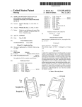
FIG. 1B is a diagram of an alternative embodiment of the
simulation device;
used to sense the acoustical vibrations. The electrical signals
generated by the piezoelectric crystal in response to the
obtained when the following detailed description of the
preferred embodiment is considered in conjunction with the
following drawings, in which:
FIG. 1A is a diagram of the simulation device according
60
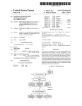
FIG. 2 is a diagram of a module in the simulation device
of the signal that are not produced by the ?ring mechanism.
of FIG. 1A containing a piezoelectric crystal and circuitry
responsive to the piezoelectric crystal for powering a laser
Sensney discloses either a high pass ?lter or a bandpass ?lter
diode;
vibrations are passed through a ?lter to remove components
to select the desired frequency corresponding to the fre
quency of the acoustical energy generated by the ?ring
mechanism of a ?rearm. However, use of such a frequency
discrimination device is dif?cult to implement, as the fre
'
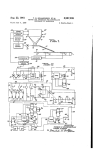
FIG. 3 is a schematic diagram of circuitry responsive to
65
acoustical energy generated by the activation of the ?ring
mechanism of the handgun for powering a laser diode to
emit a laser beam onto a target; and
5,605,461
3
4
FIG. 4 is a schematic diagram of the circuitry of FIG. 3
in which the on/off switch has been replaced by REED relay
on the target 20. This streak lets the user know that he or she
is ?ring the handgun improperly. Thus, use of the simulation
device 12 allows a user to practice ?ring the handgun 10
without the need for real bullets. A further advantage is that
circuitry.
a user can practice ?ring the handgun 10 in the convenience
DETAILED DESCRIPTION OF THE
PREFERRED EMBODIMENT
of his or her own home, without having to go to a practice
?ring range.
Referring now to FIG. 1A, a simulation device 12 accord
ing to the present invention is shown attached to a handgun
10. It is appreciated that the simulation device 12 can be
used with other types of ?rearms, such as ri?es. In the
The simulation device 12 can also be utilized as a replace
ment for tracer bullets when used in conjunction with a
10
preferred embodiment, the attachment of the simulation
device 12 to the handgun 10 is accomplished via a mounting
bracket 13, which is attached with adhesives to the bottom
of the barrel 22 of the handgun 10. The simulation device 12
includes a housing 40, which is slidably mounted onto the
mounting bracket 13. Enclosed in the housing 40 of the
simulation device 12 is a battery 46 and a cylindrical shaped
module 44, which houses a piezoelectric crystal for detect
loaded handgun 10. The laser beam generated by the simu
lation device 12 upon the ?ring of the handgun 10 indicates
where the bullet has been ?red. Preferably, a simulation
device 12 for use in the tracer mode includes further means
for adjusting the on time of the laser diode device 42, such
that the laser spot can be observed by a person wearing night
vision equipment. A handgun 10 used in tracer mode is
adapted with a ?ash suppressor to eliminate the ?ash asso
ciated with the ?ring of the handgun 10.
20
ing the acoustical pulse generated by the activation of the
Refen‘ing now to FIG. 1B, an alternative embodiment is
shown of the simulation device 12. In the alternative
?ring mechanism on the handgun 10. It is understood that
other acoustic sensors, such as various other microphone
embodiment, a shaft 26 has been provided for ?tting down
the bore of the barrel 22 of the handgun 10. Clamps 28a and
designs, can be used instead of the piezoelectric crystal. The
?ring mechanism includes a hammer 18 and a ?ring pin (not
shown) located inside the handgun 10. When a trigger 16 is
pulled, the hammer 18 rises and falls on the ?ring pin. This
28b are used to secure the simulation device 12 to the tip 24
25
causes acoustical energy to be generated in the frame of the
ever, use of the simulation device 12 in this manner may
handgun 10.
The device 12 according to the present invention can also
be used with a loaded handgun 10, such as when used in _
tracer mode. In this case, pulling the trigger 16 would ?re the
weapon, which would generate much greater acoustical
energy. As a result, overvoltage protection circuitry is
energy generated by the ?ring of a bullet. In either case,
however, the amplitude of the acoustical energy generated
by the activation of the ?ring mechanism is much greater
than any acoustical energy that could be caused by other
stimuli during normal use of the handgun 10.
The high amplitude pulse generated by the activation of
detail. For clarity, the components shown in FIG. 2 are not
drawn to scale. Enclosed in the casing 48 of the module 44
the ?ring mechanism moves in a direction generally parallel
to the axis B—B' of the barrel 22 of the gun 10. The pulse
generate an electrical pulse to activate a laser diode device
42, which emits a beam directed at a target 20. The laser
are a circuit board 54, the laser diode device 42 and a
45
beam is directed through a lens 11 in the housing 40.
An on/off switch 30 is provided on the external surface of
piezoelectric crystal 58. The laser diode device 42 is elec
trically connected to the circuit board 54 by electrical wires
62. Circuitry for responding to the piezoelectric crystal 58
and for activating the laser diode device 42 are implemented
on the upper surface 60 of the circuit board 54. For better
clarity, the details of how the circuit board 54 and the laser
diode device 42 are mounted inside the casing 48 of the
the housing 40 to allow the user to disable the simulation
device 12. In addition, a switch 32 is provided to allow the
user to manually turn on the laser diode device 42 for aiming
module 44 are not shown, as those details are readily
the handgun 10. Preferably, the manual switch 32 is located
on the handle 21 of the handgun 10 for convenient access by
the user. The switch 32 is connected to the simulation device 55
12 via an electrical wire 31. In an alternative embodiment,
the on/off switch 30 can be removed, replaced with a plug
in line with the manual switch 32. The plug is connected to
the module 44 in such a manner that reversing its connection
allows the manual switch 32 to act as an on/off switch. 60
Removal of the on/oif switch 30 allows for further space
savings.
The laser diode device 42 is preferably activated for a few
milliseconds in response to the trigger 16 being pulled to
allow a visible spot to be temporarily generated on the target
20. If the handgun 10 is pulled slightly to a side when the
trigger 16 is being pulled by the user, a streak is developed
present a safety hazard if the user is not careful, since ?ring
a live bullet with the device 12 ?tted down the bore of the
barrel 22 will cause the handgun 10 to explode.
In yet another embodiment, the simulation device 12 is
encased in a housing shaped like a ?anged cartridge, which
can be inserted from the rear of the barrel 22 by temporarily
removing the weapon slide 14 of the handgun 10. This
con?guration also allows the simulation device 12 to be used
without permanently mounting it to the handgun 10, while
ensuring that live bullets cannot accidentally be ?red.
Referring now to FIG. 2, the module 44 containing the
piezoelectric crystal and other circuitry is shown in greater
included in the device 12 to protect it from the acoustical
is sensed by the piezoelectric crystal element included in the
module 44. In response, other circuitry in the module 44
of the barrel 22. The alternative embodiment allows the
simulation device 12 to be more easily retro?tted to existing
?rearms without the need for permanent mounting. How
65
apparent to those skilled in the art. The module 44 is
positioned such that its length runs along a line A—A'. The
line A—A' is generally parallel to the axis B—B' of the
barrel 22 of the handgun 10. The circuit board 54 is mounted
inside the casing 48 of the module 44 such that the surface
60 of the circuit board 54 is also generally parallel to the line
A—A'.
A slot 56 is cut along the width of the circuit board 54 at
one end. One edge 51 of a cantilever beam 52 is ?tted into
the slot 56. The cantilever beam 52 protrudes from the
bottom surface of the circuit board 54, and its front surface
57 is generally perpendicular to the bottom surface of the
circuit board 54. The front surface 57 of the cantilever beam
52 is also generally perpendicular to the line A—A'. The
piezoelectric crystal 58 is made from a material known as
polyvinylidene ?uoride, which is ?exible in nature and is not
5,605,461
5
6
subject to fracture as are most other piezo materials. A thin
wiper of a potentiometer 117, which has its ?xed resistor
connected between the supply node V+ and the node T—.
The output of the ampli?er 106 is connected to the base of
?lm of the piezoelectric crystal 58 is coated onto the front
surface 57 of the cantilever beam 52, such that the surface
of the piezoelectric crystal 58 is also generally perpendicular
to the line A—A'. The piezoelectric crystal 58 is preferably
an NPN transistor 118 through a resistor 120. The emitter of
the transistor 118 is connected to node V— and its collector
unidirectional; that is, it is more sensitive to acoustical
is connected to a node M—.
energy traveling along one direction and much less sensitive
to acoustical energy traveling in a perpendicular direction.
Thus, in the preferred embodiment, the piezoelectric crystal
In operation, the steady state condition of the output of the
ampli?er 106 is 0 volts. A positive voltage pulse is generated
between nodes T+ and T— by the piezoelectric crystal 58 in
58 is more sensitive to acoustical energy traveling in a
response to acoustical energy, such as that generated by the
direction generally parallel to line A—A' and much less
sensitive to acoustical energy traveling in a direction gen
erally perpendicular to the line A-A'.
As discussed above, shock waves generated by the ?ring
mechanism of the handgun 10 travel in a direction generally
parallel to the axis B—B' of the barrel 22. By positioning the
15
cantilever beam 52 such that its surface 57 is generally
perpendicular to the direction of the acoustical energy pulse,
and by using a unidirectional piezo element, the piezoelec
tric crystal 58 is made more sensitive to acoustical energy
generated by the ?ring mechanism.
?ring mechanism of the handgun 10. The piezoelectric
crystal 58 may also generate a voltage pulse in response to
other stimuli, which include the user bumping the handgun
10 with his or her hands. However, the voltage pulse
generated by the piezoelectric crystal 58 in response to the
latter stimuli is much smaller than the voltage pulse caused
by the hammer 18 hitting the ?ring pin when the trigger 16
is pulled. Additionally, use of a unidirectional piezo element
minimizes the sensitivity of the piezoelectric crystal 58 to
acoustical energy not moving in a direction generally par
allel to the line A—A'. The voltage pulse is provided to the
non-inverting input of the ampli?er 106 through the capaci
Additionally, the motion of the cantilever beam 52 causes
the piezoelectric crystal 58 to be even more sensitive to
tor 104, which ?lters out any DC voltage components on the
acoustical energy traveling in a direction generally parallel
input voltage. If the pulse is an excessively large voltage,
to line A——-A'. The cantilever beam 52 is made of a resilient 25 such as that generated when an actual bullet is ?red, the
material, and shock waves generated by the ?ring mecha
varistor 103 protects the ampli?er 106 by limiting the
nism of the gun causes the cantilever beam 52 to initially
de?ect in the direction of the shock waves. Due to its
magnitude of the voltage that can exist at the non-inverting
resilient nature, the cantilever beam then swings back in the
opposite direction to begin oscillating. After a short while,
the oscillation of the cantilever beam 52 dies down.
In response to the acoustical energy pulse, the piezoelec
tric crystal 58 generates electrical pulses, which are routed
to circuitry on the circuit board 54 via solder pads 50.
this by shunting current from the node connected to the
non-inverting input of the ampli?er 106 to node T—.
Triggering circuitry and driver circuitry on the circuit board
54 then provides electrical signals through electrical wires
62 to activate the laser diode device 42, which responds by
emitting a laser beam.
Referring now to FIG. 3, a schematic diagram is shown of
a trigger circuit 100 responsive to acoustical energy gener
input of the ampli?er 106. The varistor 103 accomplishes
If the voltage pulse provided to the non-inverting input is
above a certain threshold voltage, then the ampli?er 106
drives its output to a positive voltage. The threshold voltage
is determined by the potentiometer 117. By varying the
35
voltage value is variable to allow for ?exibility so that the
threshold value can be adjusted if needed according to the
type of gun and the environment of anticipated use. If the
40
ated in the handgun 10 and a driver circuit 101 for powering
the laser diode 42, both of which are implemented on the
circuit board 54. In response to the high amplitude acoustical
energy generated by the hammer l8 falling on the ?ring pin
when the trigger 16 is pulled, the piezoelectric crystal 58
wiper location of the potentiometer 117, the voltage at the
inverting input of the ampli?er is varied. The threshold
45
input voltage pulse has a magnitude that is lower than the
threshold voltage, which would usually be the case for
external stimuli provided to the handgun 10 other than the
activation of the ?ring mechanism, the input voltage pulse is
ignored. If the voltage pulse is of su?icient magnitude, the
positive voltage developed at the output of the ampli?er 106
provides a voltage pulse between nodes T+ and T—. A
causes a bias voltage to be developed at the non-inverting
resistor 102 is connected between the nodes T+ and T— to
remove any DC static charges from the outputs of the
input of the ampli?er 106 through the voltage divider
piezoelectric crystal 58. A capacitor 104 is connected
between node T+ and the non-inverting input of an ampli?er
106 to further provide DC blocking. The power supply
inputs to the ampli?er 106 are provided by the battery 46,
50
The capacitor 116 is gradually charged to the bias voltage
existing at the non-inverting input of the ampli?er 106
which is connected between supply nodes V+ and V—. The
battery voltage across the battery 46 is preferably 3 volts. A
resistor 108 is connected between the non-inverting input of
the ampli?er 106 and node T—, and a feedback resistor 110
is connected between the non-inverting input and the output
through the resistor 112. When the voltage across the
capacitor 116 reaches the bias voltage existing on the
non-inverting input of the ampli?er 106, the ampli?er 106 is
turned o?” since the voltage difference between the inputs of
the ampli?er 106 is zero. As a result, the output of the
ampli?er 106 is driven to zero volts, which causes the
of the ampli?er 106. A high voltage protection device 103,
preferably a varistor, is connected between the non-inverting
input of the ampli?er 106 and node T—. The inverting input
transistor 118 to shut off. The capacitor 116 is then gradually
discharged back down to zero volts through the resistor 112.
It is noted that the output of the ampli?er 106 will never go
of the ampli?er 106 is connected to the cathode of a diode
114 and to one node of a capacitor 116. The anode of the
diode 114 and the second node of the capacitor 116 are
connected to the node T—. A feedback resistor 112 is
connected between the output of the ampli?er 106 and its
inverting input. In addition, a resistor 115 is connected
between the inverting input of the ampli?er 106 and the
formed by the resistors 108 and 110. The voltage level of the
bias voltage is deterrrrined by the ratio of the resistors 108
and 110.
negative in the preferred embodiment, since the negative
power supply input of the ampli?er 106 is connected to node
T—, which remains at zero volts. The effective pulse width
65
of the output signal from the ampli?er 106 is determined by
the RC timing formed by the resistor 112 and the capacitor
116 and by the bias voltage determined by the resistors 108
5,605,461
7
8
and 110. The pulse width of the output pulse of the ampli?er
Portions of the emitted laser beam from the laser diode
106 is preferably set at a few milliseconds.
The diode 114 is provided to prevent oscillation and to
ensure a one-shot pulse output at the output of the ampli?er
energy from the laser diode 153 causes the effective resis
tance of the pin diode 152 to decrease. With the decrease in
153 are received by the pin diode 152. The emitted light
106. A high voltage protection device or varistor 122 is
the resistance of the pin diode 152, the voltage seen at the
connected between nodes V+ and V— to protect the ampli?er
non-inverting input of the ampli?er 146 is proportionately
106 from high voltage conditions, such as those caused by
static charges. Also, the on/off switch 30 is connected
between nodes T- and V—. If the onlo?“ switch 30 is set in
the open position, the trigger circuit 100 is disabled.
In the driver circuit 101, the external manual switch 32 is
connected between node M— and node V—- to manually turn
increased. This increase is directly translated to the output of
the ampli?er 146, which in turn causes the voltage at the
inverting input of the ampli?er 136 to increase. Thus the
higher the power output of the laser diode 153, the higher the
voltage at the inverting input of the amplifier 136. This
increase in the voltage at the inverting input of the ampli?er
136 reduces the voltage difference at the inputs of the
ampli?er 136, which causes the output voltage of the ampli
on the laser diode device 42 if desired. In normal operation,
the switch 30 is closed and the switch 32 is open. When the
?er 136 to be reduced. As a result, the feedback path
transistor 118 is turned on by the ampli?er 106, the laser
provided by the pin diode 152, the voltage divider formed
driver circuit 101 is energized by allowing the battery
from resistors 148 and 150, the voltage follower 146 and a
voltage divider formed from the resistors 142 and 144,
voltage to be developed across nodes V+ and M—. The anode
of a Zener diode 134 is connected to node M— and its
cathode is connected to the non-inverting input of an ampli
serves to control the amount of current that can ?ow through
?er 136. The supply voltage inputs of the ampli?er 136 are
the laser diode 153 by adjusting the base current of the
transistor 154.
High voltage surges that may appear at the non-inverting
input of the ampli?er 136 are dampened by the RC network
formed by the resistor 158 and the capacitor 160. Further, the
connected to nodes V+ and M—. A capacitor 137 is con—
nected between nodes V+ and M— to remove high frequency
20
noise. Another capacitor 138 for removing high frequency
noise signals is connected between the non-inverting input
of the ampli?er 136 and node M—. A resistor 140 is con
nected between the supply node V+ and the non-inverting
input of the ampli?er 136. The inverting input of the
25
resistor 156 serves as a current limiting device to protect the
laser diode 153. A Zener diode 162 is connected between the
power supply node V+ and node M- to serve as a high
ampli?er 136 is connected to the center node of a voltage
divider formed by resistors 142 and 144. The other node of
the resistor 144 is connected to node M- and the other node
of the resistor 142 is connected to the output of an ampli?er
146. The ampli?er 146 is con?gured as a voltage follower
between nodes V+ and M- at the desired level.
In an alternative embodiment, the switch 30 can be
having a unity voltage gain. The output of the ampli?er 146
is connected directly to its inverting input. A resistor 150 is
embodiment, shown in FIG. 4, to which reference is now
voltage protection device. The Zener diode 162 is capable of
passing large amounts of current to regulate the voltage
eliminated for improved reliability and space savings. In this
connected between the non-inverting input of the ampli?er
made, the negative terminal of the battery 124 is still
146 and node M—. A resistor 148 is connected between the
connected to node V—, but its positive terminal is connected
instead to a Reed relay 406, which takes the place of the
switch 30. When energized, the relay 406 connects the
positive terminal of the battery 124 to node V+ when output
non-inverting input of the ampli?er 146 and the anode of a
pin diode 152, which is essentially a photodetecting diode.
The resistors 148 and 150 form a voltage divider.
The cathode of the pin diode 152 is connected to the
supply node V+ and also to the anode of a laser diode 153.
The pin diode 152 and the laser diode 153 are located inside
the laser diode device 42. The cathode of the laser diode 153
bit 21 of a 22-bit counter 402 is deasserted low. When the
relay 406 is deenergized, i.e., node V+ is disconnected from
the positive terminal of the battery 124, power is removed
from the trigger circuit 100. The power supply terminals of
the counter 402 are connected to the positive and negative
terminals of the battery 124. The counter 402 also has a
RST* input connected to node M—, which is connected
45
through the manual switch 32 to node V—.
protect the laser diode 153 from high frequency switching
currents occurring in power turn-on states. The emitter of the
When the manual switch 32 is closed, the RST* input of
transistor 154 is connected to node M— and its base is
the counter 402 is pulled low, causing the counter 402 to
connected to the output of the ampli?er 136 through a
reset to the value 0. When the switch 32 is released, the
resistor 158. A capacitor 160 is also connected between the 50 counter 402 begins to count. The counter 402 is clocked by
base of the transistor 154 and node M—. In addition, a
an oscillator 404 comprising two resistors 408 and 410 and
capacitor 164 is connected between the cathode of the laser
a capacitor 412 connected in parallel, which preferably
diode 153 and the positive supply node V+ to remove high
generate a l KHz clock. At this point, output bit 21 is low,
is connected to the collector of an NPN transistor 154
through a resistor 156. A capacitor 164 is connected between
the cathode of the laser diode 153 and node V+ to bypass and
frequency noise signals.
In operation, the voltage at the non-inverting input of the
ampli?er 136 is regulated by the Zener diode 134 when the
which energizes the relay 406 to provide power to the trigger
55
circuit 100, as well as to the driver circuit 101 while the
manual switch 32 remains closed. When the counter 402
NPN transistor 118 is turned on. In response to this regulated
counts to the value 221, which is approximately 33 minutes
voltage, which is preferably approximately 1.2 volts, the
ampli?er 136 drives its output to a positive voltage, thereby
later, output bit 21 is asserted high to deenergize the relay
406, thereby removing power from the trigger circuit 100.
turning the transistor 154 on. When the transistor 154 is
turned on, current is allowed to flow from the supply node
V+ through the laser diode 153, the resistor 156 and the
transistor 154 to node M—. The current ?ow through the laser
Output bit 21 is also connected to a clock inhibit input of the
counter 402. When the clock inhibit input is asserted high,
the counter 402 stops counting.
Thus, by activating switch 32, the relay 406 is energized
diode 153 causes a laser beam to be emitted. As the laser
to provide power to the trigger circuit 100. At this point, the
diode 153 is turned on only for as long as the transistor 118 65 laser diode 153 is also manually turned on. When the manual
is turned on, the duration of the laser beam is determined by
the resistor 112 and the capacitor 116.
switch 32 is released, the laser diode 153 turns Oh0 but the
relay 406 remains energized for approximately 33 minutes,
5,605,461
10
9
keeping the trigger circuit 100 active. After 33 minutes, the
relay 406 is deenergized and the trigger circuit 100 is
powered off. In this alternative embodiment, only one switch
a second resistor connected between the non-inverting
32 is needed. As a result, the size of the simulation device
12 can be further reduced.
Thus, a device has been described that simulates the ?ring
of a ?rearm. The device includes a piezoelectric crystal for
generate a bias voltage at said non—inverting input from
a voltage developed at said ampli?er output in response
input of said ampli?er and a ground signal, wherein
said ?rst and second resistors form a voltage divider to
to said input voltage pulse.
4. The device of claim 3, wherein said activation signal
detecting high amplitude acoustic pulses generated when the
asserting means includes:
a third resistor connected between the output of said
?ring mechanism of the ?rearm is activated. The piezoelec
tric crystal provides a voltage pulse to a amplitude detecting
ampli?er and the inverting input of said ampli?er; and
a capacitor connected between the inverting input of said
circuit. If the pulse generated by the piezoelectric crystal is
above a threshold value, the amplitude detecting circuit
ampli?er and the ground signal, wherein said capacitor
is charged by the output of said ampli?er through said
third resistor, said capacitor being charged to said bias
causes a laser diode to be energized. The laser diode directs
a beam at the target to allow the user to determine where the
“shot” is ?red. The laser diode is activated for a sufficiently
long period of time to allow the laser spot to be visible to the
human eye and also to allow a streak to be developed if the
?rearm is pulled slightly by the user when the trigger is
pulled. The device is conveniently mounted under the barrel
of the ?rearm.
The foregoing disclosure and description of the invention
are illustrative and explanatory thereof, and various changes
in the size, shape, materials, components, circuit elements,
voltage to cause said ampli?er to shut off, and wherein
said predetermined duration for asserting said activa
tion signal is determined by the time constant corre
20
?er and said activation signal asserting means from
wiring connections and contacts, as well as in the details of
voltage pulses having large amplitudes generated by
the illustrated circuitry and construction and method of
said acoustical energy sensing means in response to
operation may be made without departing from the spirit of
high acoustical energy.
the invention.
1 claim:
1. A device for mounting on a ?rearm and for momen
tarily emitting a beam of light to simulate the ?ring of the
?rearm, wherein the ?rearm includes a ?ring mechanism,
30
and wherein activation of the ?ring mechanism causes an
acoustical energy pulse to be generated, the device compris
ing:
means for sensing the acoustical energy and producing a
35
acoustical energy pulse, said voltage pulse amplitude
being proportional to the energy of the acoustical
40
means for setting a threshold voltage;
an ampli?er having a non-inverting input, an inverting
input, and an output, wherein the inverting input is
coupled to said means for setting a threshold voltage
and the non-inverting input is coupled to said means for
7. The device of claim 1, further comprising:
a battery;
a manual switch being coupled to said battery and said
powering means, said manual switch when activated
causing said powering means to power said light beam
emitting means; and
relaying means coupled to said manual switch, said acti
vation signal asserting means, and said battery, wherein
said relaying means energizes to connect said battery to
said activation signal asserting means to enable asser
tion of said activation signal when said manual switch
is activated, and wherein said relaying means deener
voltage pulse having an amplitude in response to the
energy pulse;
sponding to said third resistor and said capacitor.
5. The device of claim 1, wherein said threshold voltage
setting means is adjustable to vary said threshold voltage.
6. The device of claim 1, further comprising:
means coupled to said ampli?er for protecting said ampli
45
sensing;
means coupled to the output of said ampli?er for asserting
an activation signal for at least a predetermined dura
gizes to disconnect said battery from said activation
signal asserting means to disable assertion of said
activation signal a predetermined period of time after
said manual switch is deactivated.
8. The device of claim 1, further comprising:
a battery, wherein said threshold voltage setting means
includes:
a potentiometer connected to said battery and having a
wiper, wherein said threshold voltage is developed
from said battery by said potentiometer, and wherein
the location of said wiper is adjustable for varying
tion if said voltage pulse amplitude is above said
threshold voltage;
means for emitting the beam of light when powered; and
means responsive to said activation signal and coupled to
said threshold voltage. '
9. The device of claim 1, wherein said means for sensing
the acoustical energy includes a piezoelectric crystal ele
said light beam emitting means for powering said light
beam emitting means when said activation signal is
asserted.
55
2. The device of claim 1, further comprising:
a battery, wherein said ampli?er further includes a posi
tive supply terminal and a negative supply terminal,
said positive supply terminal being connected to the
positive terminal of said battery, and said negative
supply terminal being connected to the negative termi
nal of said battery.
3. The device of claim 1, further including:
60
ment.
10. The device of claim 9, wherein the ?rearm further
includes a barrel having an axis, and wherein said piezo
electric crystal element is more sensitive to acoustical
energy pulses traveling along a speci?c direction, the device
further comprising:
a housing adapted for mounting to the ?rearm; and
means mounted inside said housing for securing said
piezoelectric crystal element, said piezoelectric crystal
element being positioned such that said speci?c direc
ampli?er and the non-inverting input of said ampli?er;
tion in which said piezoelectric crystal element is more
sensitive is generally parallel to the barrel axis of the
and
?rearm.
a ?rst resistor connected between the output of said
65
5,605,461
11
12
11. The device of claim 10, wherein said securing means
includes:
cantilever means for securing said piezoelectric crystal
element, said cantilever means having an edge and a
22. The device of claim 21, wherein said means for
generating said reference voltage includes a Zener diode
having a cathode and an anode, said cathode being con
nected to said non-inverting input of said ampli?er and said
anode being connected to a ground signal.
23. The device of claim 21, wherein said output voltage
planar surface, wherein said edge is coupled to said
housing and said piezoelectric crystal element is
attached to said planar surface, wherein said cantilever
means is resilient, wherein said planar surface is gen
erally perpendicular to the barrel axis of the ?rearm,
providing means includes a voltage divider formed from a
?rst resistor and a second resistor, said ?rst resistor being
connected between said photodetecting diode and a ?rst
node, said second resistor being connected between said ?rst
and wherein the acoustical energy pulse generated by
the activation of the ?ring mechanism de?ects said
planar surface of said cantilever means.
12. The device of claim 11, wherein said piezoelectric
crystal element is a thin ?lm piezo material coated to said
node and a ground signal, and said output voltage being
coupled to said ?rst node.
24. The device of claim 21, wherein said transistor is an
NPN bipolar junction transistor having a base, an emitter,
and a collector, said base being coupled to said ampli?er
output, said emitter being coupled to a ground signal, and
planar surface.
13. The device of claim 12, wherein said piezo material is
polyvinylidene ?uoride.
said collector being coupled to said light beam emitting
14. The device of claim 1, wherein said light beam
means.
emitting means includes a laser diode.
25. The device of claim 24, wherein said light beam
15. The device of claim 1, further comprising:
a battery, wherein said powering means further includes
switching means responsive to said activation signal,
20
anode, said cathode being coupled to said collector of said
NPN bipolar junction transistor, and said anode being
coupled to said battery.
said switching means being connected to said battery
and coupled to said light beam emitting means for
26. A device for mounting on a ?rearm and for momen
connecting said battery to said light beam emitting
means when said activation signal is asserted.
16. The device of claim 15, wherein said switching means
25
?rearm, wherein the ?rearm includes an external surface and
mechanism causes an acoustical energy pulse to be gener
17. The device of claim 15, wherein a current ?ows
ated, the device comprising:
through said light beam emitting means when said battery
30
adjusting the amount of said current ?owing through
said light beam emitting means.
18. The device of claim 17, wherein said powering means
further includes:
means coupled to said current adjusting means for detect
acoustical energy and producing a voltage pulse having
35
means, and wherein said circuit board includes:
means for setting a threshold voltage;
an ampli?er having a non-inverting input, an inverting
input, and an output, wherein the inverting input is
coupled to said means for setting a threshold voltage
45
detecting means includes a photodetecting diode.
resistance varies inversely proportionally with the intensity
50
wherein said current adjusting means includes:
means connected to the anode of said photodetecting
diode for providing an output voltage, wherein said
55
means for developing a reference voltage;
an ampli?er having a non—inverting input, an inverting
input, and an output, said non-inverting input being
mined duration if said voltage pulse amplitude is
above said threshold voltage; and
means mounted inside said housing and coupled to said
circuit board for emitting the beam of light when
powered, wherein said circuit board further includes:
means responsive to said activation signal and coupled
to said light beam emitting means for powering said
light beam emitting means when said activation
signal is asserted.
27. The device of claim 26, further including:
a ?rst resistor connected between the output of said
60
connected to said reference voltage, and said inverting
ampli?er and the non-inverting input of said ampli?er;
and
a second resistor connected between the non-inverting
input being connected to said output voltage; and
a transistor coupled to said ampli?er output and to said
light beam emitting means, said ampli?er output con
trolling the amount of current flowing through said
transistor to control said current ?owing through said
light beam emitting means.
and the non-inverting input is coupled to said sensing
means; and
means coupled to the output of said ampli?er for
asserting an activation signal for at least a predeter
21. The device of claim 20, wherein said photodetecting
diode has a resistance, wherein said photodetecting diode
output voltage varies inversely proportionally with said
resistance of said photodetecting diode;
said voltage pulse amplitude being proportional to the
energy of the acoustical energy pulse;
a circuit board mounted inside said housing, wherein said
circuit board is electrically contacted to said sensing
emitted increases.
19. The device of claim 18, wherein said threshold voltage
setting means is adjustable to vary said threshold voltage.
of the emitted light beam, wherein the cathode of said
photodetecting diode is connected to said battery, and
a housing adapted for attachment to the external surface
of the ?rearm;
means positioned inside said housing for sensing the
an amplitude in response to the acoustical energy pulse,
ing the intensity of the light beam emitted from said
light beam emitting means, wherein said adjusting
means decreases said current ?owing through said light
beam emitting means if the intensity of the light beam
20. The device of claim 18, wherein said light intensity
tarily emitting a beam of light to simulate the ?ring of the
a ?ring mechanism, and wherein activation of the ?ring
is a transistor.
voltage is connected, and wherein said powering means
further includes:
means coupled to said light beam emitting means for
emitting means is a laser diode having a cathode and an
input of said ampli?er and a ground signal, wherein
65
said ?rst and second resistors form a voltage divider to
generate a bias voltage at said non-inverting input from
a voltage developed at said ampli?er output in response
to said input voltage pulse.
5,605,461
14
13
switching means being connected to said battery and’
coupled to said light beam emitting means for connect
ing said battery to said light beam emitting means when
said activation signal is asserted.
28. The device of claim 27, wherein said activation signal
asserting means includes:
a third resistor connected between the output of said
ampli?er and the inverting input of said ampli?er; and
a capacitor connected between the inverting input of said
5
38. The device of claim 37, wherein a current ?ows
ampli?er and the ground signal, wherein said capacitor
is charged by the output of said ampli?er through said
through said light beam emitting means when said battery
voltage is connected, and wherein said powering means
third resistor, said capacitor being charged to said bias
further includes:
means coupled to said light beam emitting means for
voltage to cause said ampli?er to shutoff, and wherein
said predetermined duration for asserting said activa
tion signal is determined by the time constant corre
sponding to said third resistor and said capacitor.
29. The device of claim 26, wherein said threshold voltage
setting means is adjustable to vary said threshold voltage.
30. The device of claim 29, further comprising:
adjusting the amount of said current ?owing through
said light beam emitting means.
39. The device of claim 38, wherein said powering means
further includes:
15
ing the intensity of the light beam emitted from said
light beam emitting means, wherein said adjusting
a battery, wherein said threshold voltage setting means
includes:
a potentiometer connected to said battery and having a
means decreases said current ?owing through said light
beam emitting means if the intensity of the light beam
wiper, wherein said threshold voltage is developed
from said battery by said potentiometer, and wherein
the location of said wiper is adjustable for varying
said threshold voltage.
emitted increases.
40. The device of claim 39, wherein said light intensity
detecting means includes a photodetecting diode.
41. The device of claim 26, further comprising:
31. The device of claim 26, wherein said means for
sensing the acoustical energy includes a piezoelectric crystal
element.
25
32. The device of claim 31, wherein the ?rearm further
includes a barrel having an axis, and wherein said piezo
electric crystal element is more sensitive to acoustical
said acoustical energy sensing means in response to
high acoustical energy.
42. The device of claim 26, further comprising:
a battery;
means coupled to said circuit board for securing said
a ?rst manual switch being coupled to said battery and
piezoelectric crystal element, said piezoelectric crystal
element being positioned such that said speci?c direc
35
light beam emitting means.
43. The device of claim 26, further comprising:
element, said cantilever means having an edge and a
planar surface, wherein said edge is coupled to said
circuit board and said piezoelectric crystal element is
45
said activation signal asserting means, and said battery,
50
35. The device of claim 34, wherein said piezo material is
polyvinylidene ?uoride.
37. The device of claim 26, further comprising:
a battery, wherein said powering means includes switch
ing means responsive to said activation signal, said
a battery;
a manual switch being coupled to said battery and said
powering means, said manual switch when activated
causing said powering means to power said light beam
emitting means, wherein said circuit board further
includes relaying means coupled to said manual switch,
planar surface.
36. The device of claim 26, wherein said light beam
activation signal asserting means to enable assertion of
a second manual switch being coupled to said battery and
said powering means, said second manual switch when
activated causing said powering means to power said
cantilever means for securing said piezoelectric crystal
emitting means includes a laser diode.
said activation signal asserting means, said ?rst manual
switch when activated connecting said battery to said
said activation signal; and
?rearm.
33. The device of claim 32, wherein said securing means
includes:
attached to said planar surface, wherein said cantilever
means is resilient, wherein said planar surface is gen
erally perpendicular to the barrel axis of the ?rearm,
and wherein the acoustical energy pulse generated by
the activation of the ?ring mechanism de?ects said
planar surface of said cantilever means.
34. The device of claim 33, wherein said piezoelectric
crystal element is a thin ?lm piezo material coated to said
means coupled to said ampli?er for protecting said ampli
?er and said activation signal asserting means from
voltage pulses having large amplitudes generated by
cncrgy pulses traveling along a speci?c direction, the device
further comprising:
tion in which said piezoelectric crystal element is more
sensitive is generally parallel to the barrel axis of the
means coupled to said current adjusting means for detect
55
wherein said relaying means energizes to connect said
battery to said activation signal asserting means to
enable assertion of said activation signal when said
manual switch is activated, and wherein said relaying
means deenergizes to disconnect said battery from said
activation signal asserting means to disable assertion of
said activation signal a predetermined period of time
after said manual switch is deactivated.


