1
COMMITTED TO EXCELLENCE
Please Check for
CHANGE INFORMA TION
at the Rear of this Manual
PLOT 10
4010A01,A10,A11,A12
TERMINAL CONTROL
SYSTEM
USER'S MANUAL
Tektronix, Inc.
P.O. Box 500
Beaverton, Oregon
MANUAL PART NO.
070-2241-00
97077
First Printing FEB 1977
Revised NOV 1981
SUPPORT POLICY
This software product is designated Support Category B, as
shown on the applicable software data sheet existing at the
time of order. Tektronix' sole obligation shall be to correct
defects (non-conformance of the software to the data sheet)
as described below, without additional charge.*
During the one (1) year period following delivery, if the
customer encounters a problem with the software which his
diagnosis indicates is caused by a software defect, the
customer may submit a Software Performance Report (SPR) to
Tektronix. Tektronix will respond to problems reported in
SPRs which are caused by defects in the current unaltered
release of the software via the Maintenance Periodical for the
software, which reports code corrections, temporary
corrections, generally useful emergency by-pass and/or notice of the availability of corrected code. Software updates, if
any, released by Tektronix during the one (1) year period, will
be provided to the customer on Tektronix' standard distribution media as specified in the applicable data sheet. The
customer will be charged only for the media on which such
updates are provided, unless otherwise stated in the applicable data sheet, at Tektronix' then current media prices.
*In addition to the locations within the contiguous forty-eight
(48) United States and the District of Columbia, this service is
available in those areas where Tektronix has software support
capability.
Copyright © 1977 Tektronix, Inc. All rights reserved.
All software products including this document, all associated
tape cartridges and the programs they contain are the sole
property of Tektronix, Inc., and may not be used outside the
buyer's organization. The software products may not be
copied or reproduced in any form without the express written
permission of Tektronix, Inc. All copies and reproductions
shall be the property of Tektronix and must bear this copyright
notice and ownership statement in its entirety.
TEKTRONIX is a registered trademark of Tektronix, Inc.
TABLE OF CONTENTS
1.
Introduc tion • • • • • • • • • • • • • • •
1.1
1.2
1.3
2.
2.4
2.5
2.6
2.7
Initialization: Subroutine INITT
Termination: Subrbut"ine FINITT
Absolute Line Drawing in Screen Coordinates
Subroutine MOVABS • • • .
• • • •
Subroutine DRWABS
. . • • • • • • • • •
Subroutine PNTABS
Relative Line Drawing in Screen Coordinates
Virtual and Screen Graphics
3.1
3.2
3.3
3.4
3.5
3.6
3.7
3.8
3.9
3.10
3.11
3.12
4.
2-4
2-4
Subroutine SWINDO •
Subroutine TWINDO .
3-1
3-2
3-4
3-4
3-5
3-7
3~·8
3-8
3-8
Scaling and Stretching the Screen Windo
Clipping in Virtual Space . • • • • • •
Interchangeability of Virtual and Screen Graphics.
Dashed Line Drawing
Dashed Line Specification
3-8
3-10
3-11
3-13
3-13
Utility Routines • •
4-1
4.1
4.2
4.3
Alphanumeric Output .• •
• •••.
Entering A/N Mode: Subroutine ANMODE
A/N Character Output: Subroutine ANCHO
4-1
4-1
4-1
4.3.1
Subroutine ANSTR
4-2
A/N Character Handling • •
Using the Screen Cursor: Subroutine SCURSR
4-2
4-3
4.5.1
4-3
4.4
4.5
4010A01 User
2-1
2-2
2-2
2-2
2-3
3-1
The Virtual Window •
•• • • .
A Viewable Area in User Units
Defining the Virtual Window: Subroutine VWINDO
Subroutine DWINDO . • . . . . • • • •
Line Drawing in User (Virtual) Units:
Absolute Line Drawing • • • • • • • •
Relative Virtual Coordinate Subroutines
The Screen Window
3.7.1
3.7.2
1-1
1-2
1-2
2-1
Introductory Drawing • • •
2.1
2.2
2.3
3,
Release 3.0 and Earlier Releases .
The TEKTRONIX Terminals . . . •
A Terminal Control System Overview .
1-1
A/N String Output:
Subroutine DCURSR
@
4.6
4.7
Using the Virtual Cursor:
Terminal Status Area
4.7.1
4.7.2
4.8
4.9
4.10
4.11
4.12
4.13
4.14
4.15
4.16
4.17
Subroutine VCURSR
Subroutine SVSTAT
Subroutine RESTAT
Rescaling a Graphic Output: Subroutine RSCALE
Rotating a Graphic Output: Subroutine RROTAT • •
Subroutine RESET
Subroutine RECOVR . . . • .
Miscellaneous Utility Routines
Conversion of Inches to Screen Units:
Function KIN . . . . • • • • . . . .
Conversion of Centimeters to Screen Units:
Function of KCM . . . . • • • . . . .
Measuring the Width of Characters:
Func t ion LINWDT • • . . • . • • . • • .
Measuring the Height of Lines: Function LINHGT .
. . . •
Tabs and Margins
4-7
4-7
4-9
4-9
4-11
4-11
4-11
4-13
4-13
4-14
4-14
4-15
4.17.1
4.18
5.
Routines Which Support the 4014 or 4015 Terminal
5.1
5.2
5.3
5.4
5.5
5.6
5.7
6.
Identifying the 4014/15 Terminal:
Subroutine TERM . • • .
Modifying the Z-axis of the 4014/15 Terminal:
Subroutine C:ZAXIS . • .
. . . .
.. .
Changing the Character Size on the 4014/15 Terminal: Subroutine CHRSIZ . • . . . • .
Measuring the Size of a Character:
Subroutine CSIZE
• . • . . • • .
Incremental Plotting: Subroutine INCPLT . . • •
Check Terminal Modes: Subroutine SEEMOD
Check Terminal~ Subroutine SEETRM . • • .
4-15
4-15
4-16
4-16
4-17
4-19
4-19
5-1
5-1
5-2
5-3
5-3
5-6
5-7
5-7
Transformations • . • .
6-1
6.1
6.2
6-4
6.3
6.4
ii
Setting the Tab Table:
Subroutine TTBLSZ . . . . . . . . . .
4.17.2 Tab Setting: Subroutine SETTAB . .
4.17.3 Removing a Tab: Subroutine RSTTAB
4.17.4 The Horizontal Tab: Subroutine TABHOR
4.17.5 The Vertical Tab: Subroutine TABVER
4.17.6 Setting the Margins:
Subroutine SETMRG . . • . . • . . . .
Level Checking: Subroutine TCSLEV . . . . . . •
4-5
4-7
The Linear Transformation .
The Logarithmic Transformation
Subroutine LOGTRN . • . . . • .
The Polar Transformation
Drawing Segments Using the Polar Transformation:
Subroutine DRAWSA: Subroutine DRAWSR . . . • . .
@
6-4
6-4
6-5
4010A01User
6.5
6.6
7.
Drawing Dashed Line Segments Using Polar
Transformation: Subroutine DASHSA;
Subrouti~e DASHSR
. . . • . . . .
Using the Polar Transformation .
Input/Output Routines
7.1
7.2
7.3
7.4
7.5
7.6
7.7
7.8
7.9
7.10
7.11
7-1
···
····
Output: Subroutine TOUTST
Subroutine TOUTPT
Subroutine ANCHO
Subroutine ANSTR
Subroutine A10UT
Subroutine AOUTST
Input: Subroutine TINSTR
Subroutine TINPUT
Subroutine A1IN
Subroutine AINST
Utility I/O Routines
····
· .. . .
·
···········
····
····
····
.···········
·
········..
APPENDIX A
7-11
Dumping the Output Buffer:
7-11
I.
II.
II.
APPENDIX B
INDEX
7-2
7-2
7-2
7-3
7-3
7-3
7-4
7-4
7-5
7-5
7-6
7.11.1 Setting the Output Buffer Format:
Subroutine SETBUF . . . •
7.11.2 Examine the Output Format:
Subroutine SEEBUF • • • . •
.,
7.11.3 Examining the Useable Space in
the Output or Input Buffer
Function: LEFTIO. • . . •
7.11.4 Locating the Position of the
Graphic Beam: Subroutine SEELOC
· ..
7.12
6-6
6-7
Subroutine TSEND .
7-6
7-10
7-10
An Advanced Use of the Terminal Control
System: Circuit Drawing
A-2
Terminal Control System Common
Variables
A-6
GLOSSARY
A-8
OPTION 22 Users' Instructions
B-1
I.
Subroutine and Function Index
II.
Subject Index
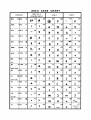
ASCII CODE CHARTS
4010A01 User
REV. A, MAR. 1978
iii
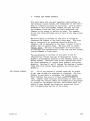
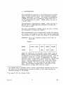
1.
INTRODUCTION
The LEVEL 1 version of the 4010A01 PLOT 10 Terminal Control
System is the equivalent of Release 3.3 of the previous
PLOT 10 Software with minor updates.
In order to allow the user to deal with many computer environments both for timesharing and minicomputers, TEKTRONIX
has developed the Terminal Control System software package.
The package is a comprehensive set of subroutines which
allows terminal-independent graphic programming; the user
needs only to select the proper subroutines at load time.
The design is basically system and computer independent and
enables the experienced programmer to work at the terminal
level and also provides the facilities for the occasional
user to operate easily at the conceptual level. The Terminal Control System consists of those subroutines which
support the TEKTRONIX 4006-1, 4010, 4012/13* and 4014/15*
Computer Display Terminals.
Those who wish to enhance PLOT 10 Terminal Control System
with 4662AOI PLOT 10 Utility Routine may then route output
of TCS to the TEKTRONIX 4662 Inter-active Digital Plotter.
RELEASE 3 AND EARLIER RELEASES
1.1 THIS MANUAL IS DESIGNED FOR ALL USERS OF RELEASES 3.0
THROUGH 3.3 AND LEVEL 1 OF THE TERMINAL CONTROL SYSTEM.
ANY USER WHO OBTAINS THE PACKAGE AFTER THE DATE OF THIS
MANUAL CAN PRESUME THAT HE HAS LEVEL 1.
* The notation 4014/15 refers to either the 4014 or the 4015 terminals, the
notation 4012/13 refers to either the 4012 or the 4013 terminal. The 4015
and 4013 terminals are in all ways the same-as their counterparts, but offer
in addition an APL character set.
401 DAD1 User
@
1-1
THE TEKTRONIX
TERMINALS
1.2
The 4006, 4010, 4012/13, and 4014/15 Computer
Display Terminals are capable of displaying both alphanumeric characters and graphic data. Once written, the
display remains visisb1e until it is erased, and it is not
necessary to continually refresh the information put up on
the screen. The 4012 is an upper and lower case ASCII
Terminal. The 4013 is an APL Terminal which also has the
ASCII character set of the 4012. The 4014 and 4015
Terminals offer upper and lower case ASCII, with the 4015
also having APL capabilities.
The 4014/15* Terminals offer in addition a write-through
capability, in which both stored and refreshed information
may be displayed. The 4014/15 Terminals have a display
area of 14.5 inches by 10.9 inches, and the user has the
option of four character sizes. The 4014/15 Terminals
with Enhanced Graphics Module** offer hardware dashed
lines and point plotting as well as incremental point
plotting. The user may also address a grid of 1024 by
1024 points or a grid of 4096 by 4096 points.
A TERMINAL CONTROL
SYSTEM OVERVIEW
1.3
The ideal that the Terminal Control System strives
for is to make the Terminal as easy to use as a pencil and
a piece of paper. The detailed programming and general
I/O handling are contained within the system; as a result
the basic Terminal capabilities are made available to the
user in a natural and practical manner.
The Terminal Control System subroutines communicate with
each other primarily through the Terminal Status Area, a
set of common variables which continuously represent the
current state of the Terminal and maintain the data and
flags necessary to generate output according to the user's
level of need. Terminal status cannot accurately be kept
when output to the Terminal is generated by other means
than through the appropriate Terminal Control System routine
or whenever the user changes status locally (e.g., uses
the PAGE or RESET key).
The package gives many graphing conveniences to the user.
Bright and dark vectors (line segments) as well as points
may be displayed on the Terminal screen. A bright vector
which can be seen on the screen, is caused by one of the
*
The notation 4014/15 refers to the 4014 or the 4015 Terminal.
4012/13 refers to either the 4012 ££ the~013 Terminal.
The notation
**
The Terminal Control System does not support special point plotting for the
Enhanced Graphics Module.
1-2
@
401 OA01 User
"draw" routines. A "move" routine will cause a dark vector,
the invisible equivalent of a bright vector; a "point"
routine causes the display of a bright spot or point. Also
included in the package are a choice of linear, logarithmic,
or polar coordinate systems, automatic scaling of graphic
data, and buffered input and output for faster, more
efficient character handling.
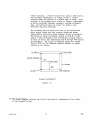
The following section deals with some of the subroutines
which output bright and dark vectors (draws and moves,
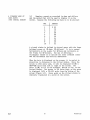
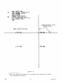
respectively) and points using Terminal screen coordinates.
The values of these coordinates should be from 0 to 1023
unless a 4014/15 Terminal with the Enhanced Graphic Module
is used (in which case addressing from 0 through 4095 points
is available). The Y-axis coordinates should not exceed
780 (or 3120 for the Enhanced Graphics Module) to remain
visible on the screen.
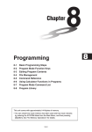
(1023,780)
(0,780)
Screen Margins
512
~(-~)·(512,390)
1
~Screen
390
1023,0)
(0,0
Screen Coordinates*
Figure 1.3
*
The Screen Margins indicate the initial settings for alphanumeric line limits
on the Terminal Screen.
4010A01 User
@
1-3
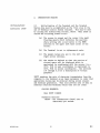
2.
INITIALIZATION:
Subroutine INITT
INTRODUCTORY DRAWING
2.1
Initialization of the Terminal and the Terminal
Status Area must be accomplished as the first step in the
use of Terminal Control System routines. This may be done
by calling the initializing routine, INITT. When INITT is
called the following events occur:
(a)
The screen is erased and the cursor (the small
floating square which indicates the position
where writing will occur) moves to the HOME
position in the upper left hand corner of the
screen.
(b)
The Terminal is set to alphanumeric mode.
(c)
The margin values are set to the left and
right screen extremes.
(d)
The window is defined so that the portion of
virtual space will be displayed which is
equivalent in coordinates with the screen [i.e.,
(275, 763) in user coordinates is equivalent to
(275, 763) in screen coordinates]. See sections
3.0 through 3.2 for a description of virtual
graphics.
INITT requires the rate of character transmission from the
computer to the Terminal as an input parameter in order that
appropriate delays may be produced during screen erasure
and hardcopy generation. This will prevent loss of data on
remotely connected Terminals while they are not ready.
CALLING SEQUENCE:
CALL INITT (IBAUD)
Parameter Entered:
IBAUD - the transmission (baud) rate in
characters per second.
4010A01 User
@
2-1
TERMINATION:
Subpoutine FINITT
2.2
When terminating a program which uses the Terminal
Control System, it may be desirable to return the Terminal
to alphanumeric mode and move the cursor to a point that
will not interfere with any previous output. All output
to the Terminal is buffered, or stored, until the user
calls a routine that dumps the buffer, or until the buffer
is full.
FINITT automatically performs these functions. It
terminates the program and outputs the contents of the
buffer. Its arguments designate the position of the
alphanumeric cursor upon program termination. FINITT
should be used, depending on the computer system, either
in conjunction with or in place of a FORTRAN STOP statement.
CALLING SEQUENCE:
CALL FINITT (IX, IY)
Parameters Entered:
IX - the screen x-coordinate of the
position to which the beam is moved
before program termination.
IY - the screen y-coordinate of the beam
termination position.
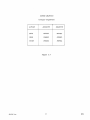
ABSOLUTE LINE
DRAWING IN
SCREEN COORDINATES
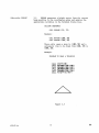
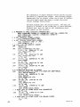
2.3
The three functions which do line drawing by
referring to screen coordinate locations are MOVABS, DRWABS,
and PNTABS. "ABS" stands for absolute; the drawing is
called absolute because it is measured from a fixed point,
the origin (0,0). The arguments of these routines are
always in integer format.
Subroutine MOVABS
2.4
The argument of MOVABS is the pair of coordinates of
the point to which a move is desired. Output starts at
the stored current beam position. This position is updated
after every line draw or other output command. In addition,
all drawings are buffered.
CALLING SEQUENCE:
CALL MOVABS (IX, IY)
Example:
CALL MOVABS (100, 150)
This call generates a move to (100, 150) so that
that drawing can proceed from there.
2-2
@
4010A01 User
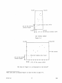
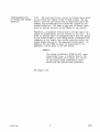
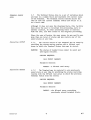
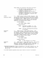
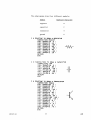
Subroutine DRWABS
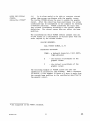
2.5
DRWABS generates a bright vector from the current
beam position to the coordinates given and updates the
appropriate variables in the Terminal Status Area.
CALLING SEQUENCE:
CALL DRWABS (IX, IY)
Example:
CALL MOVABS (100, 50)
CALL DRWABS (300, 50)
These calls cause a move to (100, 50) and a
subsequent line to be drawn from (100, 50) to
(300, 50).
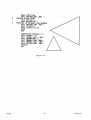
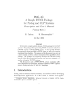
Example:
PROGRAM TO DRAW A TRIANGLE
CALL
CALL
CALL
CALL
CALL
CALL
INITT(30)
MOVABS(100,100)
DRWA8S(300,100)
DRWABSC200.187)
DRWABS(100.100)
FINITT(0,767)
Figure 2.5
4D1DAD1 User
@
2-3
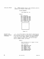
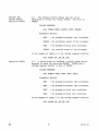
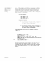
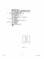
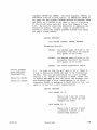
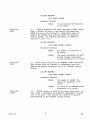
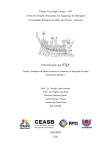
Subroutine PNTABS
2.6
PNTABS similarly moves to the coordinates given as
arguments and displays a point there.
CALLING SEQUENCE:
CALL PNTABS (IX, IY)
Example:
CALL INITT(30)
CALL
CALL
CALL
CALL
CALL
CALL
MOVABS(300,200)
DRWHBS(S00.200)
DRW~BS(500.400)
DRll.lt4BS ( 30\-).
4~)O
)
DRWABSl300.200)
PNTAB5l400.300)
CALL FINITT(0,767)
Figure 2.6
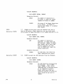
RELATIVE LINE
DRAWING IN SCREEN
COORDINATES
2.7
It is often easier to draw lines by indicating how
many horizontal and vertical screen units to move relative
to the last beam position. Negative relative movement is
to the left or down. DRWREL, MOVREL, and PNTREL perform
relative drawing in screen units. They have the same
syntax as DRWABS, MOVABS, and PNTABS.
Example:
Draw the same box as in figure 2.6 with
relative vectors.
CALL INITT~30'
CALL r-l0""ABS l 300. 200 )
CALL PRWREL(200·0)
C~LL
DRWRELt0.200)
CALL DRWRELI-200.0)
(ALL DRWRELl0.-2~0)
(ALL PNTREL(100,100'
CALL FINITT(0,767)
2-4
REV. A, MAR. 1978
4010A01 User
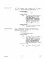
SCREEN GRAPHICS
(Integer Arguments)
ABSOLUTE
RELATIVE
MOVE
MOVABS
MOVREL
DRAW
DRWABS
DRWREL
POINT
PNTABS
PNTREL
ACTION
Figure 2.7
4D1 DAD1 User
@
2-5
3.
VIRTUAL AND SCREEN GRAPHICS
This part deals with the most important relationships in
the Terminal Control System, the translation of the User's
data to a physical location on the screen. With an understanding of this relationship between the data area and
the Terminal screen the User can freely manipulate the
display on the screen to reflect his need. For example,
he can plot three different sets of data in the same screen
display.
The first group of sections in this part (1 through 6)
discusses the display of the User's data area. This area
may be conceived of as existing virtually within "the
computer, and is analogous to the sheet of paper on which
graphic data is usually drawn. The data area is called
virtual space. The unit of measurement in virtual space
is arbitrary and representative of any unit the User wishes,
from milligrams to light years.
The second group of sections in this part (7 and 8)
discusses how virtual data may be displayed by screen
graphics in designated portions of the Terminal screen (the
screen window). Sections 9 and 10 deal specifically with
the inter-dependence of virtual space graphics and screen
graphics. Sections 11 and 12 discuss the drawing of dashed
lines with both virtual space graphics and screen space
graphics.
THE VIRTUAL WINDOW:
4D1 DAD1 User
3.1
Allor any portion of virtual space may be viewed
at any time through the technique of windowing. The User
defines in user units a rectangle, the virtual window,
which utilizes that part of virtual space he wishes to
view. Graphic lines (vectors) and portions of lines which
lie outside the virtual window are ~utomatically eliminated
or clipped by the graphic routines, while those which lie
within or pass through the window are scaled and fitted
into the appropriate portion of the screen.
@
3-1
A VIEWABLE AREA IN
USER UNITS:
(THE VIRTUAL WINDOW)
3.2
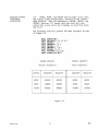
Examine a graph as conceived in days and dollars
and the method that will be used to display it on the
screen. Suppose the following raw data is to be plotted:
DAY
1
2
3
4
5
6
7
8
9
10
PROFIT
$ 30
26
42
38
40
50
54
48
40
52
A virtual window is defined in virtual space with the lower
lefthand corner at (0 days, 20 dollars). It is to extend
horizontally on the x-axis for 10 days and vertically on
the Y-axis for 40 dollars. One way of defining a
rectangular window is to specify the lower lefthand corner
and the horizontal and vertical dimensions.
When the data is displayed on the screen, it is scaled in
proportion to distances in the virtual window. Since the
screen is 1024 units wide, it will be displayed (1/10) x
1024=102 units from left to right on the screen. The
point (1,30) is 1/4 of the distance, bottom to top, on the
virtual window. The screen is 781 units high, so the point
is displayed (1/4) x 781-195 units from the bottom of the
screen (Figure 3.2). Every point on the virtual window is
similarly translated to a point on the screen.
3-2
@
4010A01 User
(10~
•
1/4 of the virtual
windoUJ height
(O~
I
•
20)
--.
+-
60)
•
•
(1~30)
Sample Data Point
(10~ 20)
1/10 of the virtual window width
THE VIRTUAL WINDOW
Figure 3.2
(O~
(1023~
780)
780)
~------------------------------~
•
-•
--
-ro-
•
(102~
•
+--
The Screen
195) Sample Data Point
•
1/4 of the screenI
windoU) height
I
I
I
I
I
I
I
I
I
I
I
I
I
I
I
I
I
I
1...... 1
1/10 of the screen width
The Data of Figure 3.2 as Displayed on the Screen*
*The code used to display Figure 3.2 may be seen on page 3-5.
4010A01 User
@
3-3
DEFINING THE
VIRTUAL WINDOW:
Subroutine VWINDO
3.3
The Terminal Control System uses one of two
subroutines to define the virtual window. The first is
VWINDO.
CALLING SEQUENCE:
CALL VWINDO (XMIN, XRANGE, YMIN, YRANGE)
Parameters Entered:
the minimum horizontal user coordinate.
XMIN
XRANGE - the horizontal extent of the rectangle.
- the minimum vertical user coordinate.
YMIN
YRANGE - the vertical extent of the rectangle.
In the example of Figure 3.2, the calling sequence would be:
CALL VWINDO (0.,10.,20.,40.)
Subroutine DWINDO
3.4
A second method of defining a virtual window may be
employed by using the subroutine DWINDO. DWINDO uses a
calling sequence similar to that of VWINDO.
CALLING SEQUENCE:
CALL DWINDO (XMIN, XMAX, YMIN, YMAX)
Parameters Entered:
XMIN
the minimum horizontal user coordinate.
XMAX
- the maximum horizontal user coordinate.
YMIN
- the minimum vertical user coordinate.
YMAX
- the maximum vertical user coordinate.
In the example of Figure 3.2, the calling sequence would be:
CALL DWINDO (0. ,10. ,20. ,60.)
3-4
@
4010A01 User
3.5
MOVEA, DRAWA, and POINTA are analogous to MOVABS,
DRWABS, and PNTABS, but they allow points outside the
virtual window to be referenced. Only those points or
portions of bright vectors (line segments) which fall
within the window boundaries, however, will be displayed;
this is known as "clipping".
LINE DRAWING IN
USER (VIRTUAL)
UNITS:
AbsoZute Line
DrauJing
CALLING SEQUENCE:
CALL MOVEA (X, Y)
CALL DRAWA (X, Y)
CALL POINTA (X, Y)
Parameters Entered:
X - the horizontal virtual (real) coordinate to
which a bright or dark vector is drawn or
at which a point is displayed.
Y - the vertical virtual (real) coordinate to
which a bright or dark vector is drawn or
at which a point is displayed.
Using subroutine POINTA, we will display the data of
Figure 3.2:
DIMENSION X( 10), Y( 10)
CALL INITT(30)
CALL VWINDO(0 .10 ,20.140 )
DATA X..... 1. 2 .. 3 .. 4. ,5 . ,6 .• ? . 8 .. 9 .' . 10 . .'
#
I
~TA
tee
V/30.
I
26, 42 . , 38. ,40 .• 50 .• 54. ,48 .• 40 .• 52 /
DO 100 1-1,10
CALL POINTA(X(I).V(I»)
CALL FINITT(0#767)
To work in user units on the screen, one could set up a
virtual window that measures eight by six units. The
following code will draw a three by three unit rectangle
with the lefthand corner at (1.,1.) and a point in the
middle.
401 DAD1 User
REV. A, MAR. 1978
3-5
CALL INITT(30)
CALL \JWINOO(0 . 8
CALL
CALL
CALL
CALL
CALL
CALL
MO~~A(l
. 0 ... 6. )
.. 1.)
DRAWA(l .4.'
ORAWA(4 .4. )
DRAWA(4.~1.)
DRAWA(1 .. 1.)
POINTA(2.S,2.S)
CALL FINITT<8,?67)
Figure 3.5
3-6
@
4010A01 User
RELATIVE VIRTUAL
COORDINATE
SUBROUTINES
3.6
MOVER, DRAWR, and POINTR draw straight lines, move,
and display points respectively, relative to the current
beam position. They are analogous to MOVREL, DRWREL, and
PNTREL, (Section 2.7) except that they deal with user
rather than screen units and clipping, as described above,
may occur.
The following code will produce the same rectangle as that
of Figure 3.5.
CALL
CALL
CALL
CALL
CALL
CALL
CALL
CALL
CALL
INITT(30)
VWINDO(O .8 .0 .• 6 . )
MOUEA(1 .. 1.)
DRAWR(0 .3.)
DRAWR(3 .. 0.)
DRAWR(0. ,-3. )
ORAWR(-3 .. 0. )
POINTR(1.S.1.5)
FINITT(0,?67)
SCREEN GRAPHICS
VIRTUAL GRAPHICS
(Integer Arguments)
(Real Arguments)
ACTION
ABSOLUTE
RELATIVE
ABSOLUTE
RELATIVE
MOVE
MO VA BS
MOVREL
MOVEA
MOVER
DRAW
DRWABS
DRWREL
DRAWA
DRAWR
POINT
PNTABS
PNTREL
POINTA
POINTR
Figure 3.6
4010A01 User
@
3-7
THE SCREEN WINDOW
3.7
So far, to display a drawing in virtual space the
entire screen has been used. But any rectangular portion
of the screen can be used as a display area. This display
area is called the screen window, and it is defined by the
subroutines SWINDO and TWINDO. The two subroutines stand
in the same relation to each other as do VWINDO and DWINDO
(see Sections 3.3 and 3.4); like all arguments in screen
terms, the arguments of SWINDO and TWINDO are in integer
format.
Subroutine SWINDO
3.7.1
CALLING SEQUENCE:
CALL SWINDO (MINX,
LENX, MINY, LENY)
Parameters Entered:
MINX - the minimum horizontal screen coordinate.
LENX - the horizontal extent of the rectangle.
MINY - the minimum vertical screen coordinate.
LENY - the vertical extent of the rectangle.
Subroutine TWINDO
3.7.2
CALLING SEQUENCE:
CALL TWINDO (MINX, MAXX, MINY, MAXY)
Parameters Entered:
MINX - the minimum horizontal screen coordinate.
MAXX
the maximum horizontal screen coordinate.
MINY - the minimum vertical screen coordinate.
MAXY - the maximum vertical screen coordinate.
SCALING AND
STRETCHING THE
SCREEN WINDOW
3.8
The points of the virtual window are scaled to fit
into the screen window in the same manner as they previously
fitted into the entire screen. Consider again the data of
Figure 3.2.
The following program illustrates how the size and shape of
the screen window can be manipulated by changing the
dimensions of TWINDO. Note that all of the virtual data
is displayed in each case.
3-8
@
4010A01 User
c
~
C
*
DEMONSTRATION OF SCALING AND STRETCHING
CALL INITT (30)
CALL OWINDO (0 .10 .. 20 ,60.)
DRAW THE ~AME GRAPH IN FOUR TERMINAL WINDOWS
CALL TWINDO (0.200,550.700)
CALL GRAFIT
CALL TWI~DO (300.900,550.700)
CALL
C
'*
C
*
~RAFIT
CALL TWINDO (0.a00.0.~S0)
(;ALL GRHFIT
CALL TWINDO (300,900.e.450)
CALL GRAFIT
MA~:E HARDCOPY
Cf4LL HDCOPY
CALL FINITT~0.760)
Er'tD
SUBPOUTINE TO. DRAW GRAPH WHICH FILLS TERMINAL WINDOW
SUBROUTINE GRAFIT
DIMENSION X(10),V(10)
DATA X/l .2 ,3 .. ".,5.,6.,7.,8., g. , 10. /
DATA Y,"30. ,26./42. ,38. ,40 ,50. ,5-4 .....S ... 40. ,52 ,/
CALL MOUEA(X( 1 ). y( 1»
100
DO 100 1-1.10
CALL DRAWA(X(I),Y(I»
CALL MOVEA(O. ,20 )
CALL DRAWA(10.,80.)
CALL DRAWA( 10 .• 60. )
CALL DRAWA(0 .• 60.)
CALL DRAWA(0 .. 20. )
RETURN
END
Figure 3.8
401 OA01 User
@
3-9
3.9
To see only a portion of the data, the user can
change VWINDO/nWINDO to include only the desired section.
When drawing is done in user (virtual) units, that portion
of the drawing is clipped which occurs outside the present
virtual window. Clipping occurs in all virtual graphics:
CLIPPING IN
VIRTUAL SPACE.'
DIMENSION X(10)#V(10)
DATA X/i ... e. 3 ... -4 ... 5 ... 6. 7 ... 8 ... 9 ... 10 . /
DATA Y /30 .• 2S. , ~2 .• 38 . ,,~0 ... 50 ... 5~ ... ~S ... <40 ... 52 . /
#
lee
#
CALL INITT(30)
CALL SWINDO(~00,,300,200,~00)
CALL VWINDO(3 ,5 .. <40 ,15 )
CALL MOVEA(X(l).Y(l»
DO 100 1-1.10
CALL DRAWACX(I)"Y(I»
CALL MOVABS(<400 . 200)
CALL DRWABS(70e.200)
CALL DRWABS(?00 . 600)
CALL DRWABS<400 . S00)
CALL DRWABS(~e0.200)
CALL FINITT(0 . ?6?)
STOP
END
Figure 3.9
3-10
@
401 OA01 User
INTERCHANGEABILITY
OF VIRTUAL AND SCREEN
GRAPHICS:
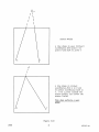
3.10
The user may locate a point in virtual space which
is not within the limits of the virtual window. He may
draw to and from this point with no difficulty since the
drawing will automatically be scaled and clipped by the
window definition. The same is not true of screen space,
which is defined entirely by the limits of the screen.
Therefore, a transition from screen to virtual space can
always be accomplished, but the reverse is not true. If a
point in virtual space is designated which does not appear
on the screen window, a draw using screen coordinates will
originate at the beam's last visible position within the
screen window and not at the expected virtual point. In
addition the user must be aware of wrap-around if he
addresses a point which is off the screen.
Example:
The screen coordinates (1500,0) will cause
wrap-around (e.g., A relative draw to the
above coordinates will result in a vector
on the X-axis drawn (1500-1024) raster
units from the current beam position.)
See Figure 3.10
4010A01 User
@
3-11
/\ B
/ \
/ \
/
/
\
\
\
Screen Window
A line drawn in user (virtual)
coordinates from point A to
point B and back to point C
c
A line drawn in virtual
coordinates from A to Band
in screen coordinates back to
C. B is a point outside the
screen window~ but within the
screen limits.
This draw reflects a user
error
c
Figure 3.10
3-12
@
4010A01 User
DASHED LINE
DRAWING
3.11
Dashed lines of nearly infinite variety may be
drawn through the use of the Terminal Control System in
both virtual and screen space. The four basic dashed
line subroutines are DSHABS, DSHREL, DASHA, and DASHR.
These routines are analogous to DRWABS, DRWREL (Sections
2.5 and 2.7), DRAWA, and DRAWR (Sections 3.5 and 3.6);
each dashed line subroutine, however, has a third, integerformat argument. This third argument controls the type of
dashed line displayed, and it can take any integer value
from -1 to the largest integer, less than or equal to
9999999999, which your computer can accept.
CALLING SEQUENCES:
CALL
CALL
CALL
CALL
DSHABS (IX, IY, L)
DSHREL (IX, IY, L)
DASHA (X, Y, L)
DASHR (X, Y, L)
IX, IY (integer) and X, Y (real) are the coordinates the
dashed line is drawn to and L is the dash type specification.
DASHED LINE
SPECIFICATIONS:
Parameter L
3.12
Software dashed lines may be specified on any
TEKTRONIX graphics display terminal with a concatenation
of the following code numbers:
1 - 5 raster units. visible
2 - 5 raster units, invisible
3 - 10 raster units, visible
4 - 10 raster units, invisible
5 - 25 raster units, visible
6 - 25 raster units, invisible
7 - 50 raster units, visible
8 - 50 raster units, invisible
Example:
CALL DSHABS
(200,
700, 3454)
The software also uses single digits to specify (L):
-1 causes a move
o causes a draw
9 alternate visible and invisible segments
between data points.
Example:
CALL DSHABS
401 OA01 User
REV A, APR 1980
(200, 700,
-1)
3-13
Four types of hardware dashed lines are available on the
4014/15 Terminal with Enhanced Graphic Module (see TERM,
Section 5.1). The hardware dashed line specifications are
fast and efficient and may be used by any TEKTRONIX Graphic
Display Terminal. If the terminal hardware is not capable
of generating the hardware dash, then the software will
approximate the type according to the following key:
1 - a
2 - a
3 - a
4 - a
dotted line
dash-dot line
short-dashed line
long-dashed line
Example:
CALL DSHABS (200, 700, 2)
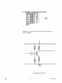
The following example illustrates two software-simulated,
hardware dash types (2 and 3). Function KIN (Section 4.13),
here to make relative draws:
3-14
@
4010A01 User
C
*
C
*
C
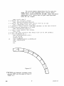
*
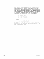
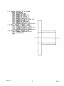
SAMPLE DR~UING OF A FLANGE
CALL INITT(38)
CALL ~OVABS(lee,58)
C~LL DRWREL(0.KIN(S.»
CALL DRWREL(KIN(0.S).8)
CALL DRWREL(0,-KIN(S.»
CALL DRWREL(-KIN(0S),0)
CALL MOVREL(KIN(0.S),KIN(1.5»
CALL DR~EL(KIN(a.e),e)
CALL DRWREL(0,KIN(2.0»
CALL DRWREL(-KIN(2.0),0)
CALL MOUREL<KIN(20),-KIN(0.2S»
DRAW DASHED ~HIDDEN~ LINES
CALL DSHREL(-KIN(2.S),0,3)
CALL MOVREL(KIN(2.S).-KIN(1.S»
CALL DSHREL(-KIN(2.5),0,3)
CALL MOVREL(KIN(3.0),KIN(0.7S»
DRAW DASHED 'CENTER LINE~
CALL DSHREL(-KIN(3.S).0,2)
CALL FINITT(0,0)
END
~---.------------------
~----.------------------
4010A01 User
@
3-15
SCREEN GRAPHICS
VIRTUAL GRAPHICS
(Integep Apguments)
ACTION
(ReaZ Apguments)
ABSOLUTE
RELATIVE
MOVE
MO VA BS
MOVREL
MOVEA
MOVER
DRAW
DRWABS
DRWREL
DRAWA
DRAWR
POINT
PNTABS
PNTREL
POINTA
POINTR
DASH
DSHABS
DSHREL
DASHA
DASHR
ABSOLUTE
RELATIVE
Figure 3.12
3-16
@
4D1DAD1 User
4.
UTILITY ROUTINES
ALPHANUMERIC
OUTPUT
4.1
By allowing the Terminal Control System to monitor
alphanumeric (A/N) output rather than using FORTRAN READ
and WRITE statements, it is possible to maintain Terminal
status, especially the tracking of the beam position. This
tracking is required for tab and margin control as well as
for facilitating the mixture of A/N and graphic output. As
with graphic output, alphanumeric output is buffered, or
stored, until a routine is called to dump the buffer, or
until the buffer is full.
ENTERING A/N
MODE:
Subroutine ARMODE
4.2
At times the user may wish to output A/N data other
than through the Terminal Control System. In such cases it
is the user's responsibility to insure that the Terminal is
in A/N mode. This can be done by using ANMODE. It is not
necessary to call ANMODE when using the Terminal Control
System routines as they will automatically call it whenever
necessary. ANMODE can be used to dump the output buffer.*
CALLING SEQUENCE:
CALL ANMODE
A/N CHARACTER
OUTPUT:
Subroutine ANCHO**
4.3
Non-control alphanumeric characters are monitored
when output through ANCHO. A/N mode will be entered if
necessary and the Terminal Status Area representation of
the screen beam position is updated as characters are
output. If the outputting of the character advances the
beam beyond the right margin setting, a new line is
automatically generated.
The input argument is assumed to be a 7-bit ASCII, noncontrol character which is right-adjusted within an integer
word. ANCHO does not check this input varia~le. Any but
the expected input will result in erroneous beam status
information.
* The positioning on the Terminal screen of non-Terminal Control System output
(such as a FORTRAN WRITE) is dependent upon the way in which the software package
is implemented on your computer. See Section 7.11.1 for details. If all output
is through the Terminal Control System, no such implementation dependencies exist.
** This routine is also discussed in Section 7.3.
4010A01 User
@
4-1
ANCHO updates the beam according to the character size set.
All character sizes are correctly updated in 4096 grid
space. In 1024 space, however, only the large size
characters are correctly updated; the other sizes are
fractional screen units in width, forcing the beam update
to be an approximation to within 1/2 a screen unit of the
true beam position.
CALLING SEQUENCE:
CALL ANCHO (ICHAR)
Parameter Entered:
ICHAR - An integer which represents a
7-bit ASCII character, rightadjusted. NOT a control character.
For an example of ANCHO, see Section 5.4.
A/N STRING OUTPUT
Subroutine ANSTR*
4.3.1
ANSTR functions in all respects like ANCHO above,
except that it allows the user to output an alphanumeric
string instead of a single character. The arguments of
ANSTR are NCHAR, the number of characters to be output, and
NADE, the arrary of ASCII decimal equivalent integers which
represents the string to be output.
CALLING SEQUENCE:
CALL ANSTR (NCHAR, NADE)
Parameters Entered:
NCHAR
the number of characters to be
output.
NADE
An array containing the ASCII
decimal integer equivalents for
the characters to be output.
4.4
AIN CHARACTER HANDLING
Subroutine NEWLIN
Generates a line feed and carriage return.
Subroutine LINEF
CALL NEWLIN
,Generates a line feed.
CALL LINEF
*This routine is also discussed in Section 7.4.
4-2
@
4010A01 User
Subroutine CARTN
Generates a carriage return
CALL CARTN
Subroutine HOME
Moves the alphanumeric cursor to the upper left corner of
the screen.
CALL ROME
Subroutine BAKSP*
Generates a backspace.
CALL BAKSP
Subroutine NEWPAG
Erases the Terminal screen and returns the alphanumeric
cursor to the ROME position.
CALL NEWPAG
USING THE SCREEN
CURSOR:
4.5
The graphic cursor may be used to specify screen
coordinates directly. Calling SCURSR will activate the
graphic cursor, allowing the user to position it. The
cursor position is transmitted to the computer when a
keyboard character is struck. This character along with
the input position is returned as arguments by SCURSR.
The Terminal Control System compensates for effects on
the beam position caused by the graphic cursor.
Subroutine SCURSR**
CALLING SEQUENCE:
CALL SCURSR (ICRAR, IX, IY)
Parameters Returned:
ICHAR - a keyboard character, 7-bit ASCII
right-adjusted.
IX
- the screen x-coordinate of the
graphic cursor.
IY
- the screen y-coordinate of the
graphic cursor.
The following example (Figure 4.5) demonstrates a use of
the screen cursor. ANMODE (Section.4.2) is called to print
out the coordinates of the screen cursor.
Subroutine DCURSR**
*
4.5.1 DCURSR accomplishes the same function as SCURSR
above. It's calling sequence and arguments are also the
same.
Not supported on the 4006-1 Terminal. To achieve a backspace, substitute the
following:
CALL MOVREL (-LINWDT(1),0)
This is done automatically
for Terminal type
(See subroutine TERM)
°
**
Not supported on the 4006-1 Terminal.
4010A01 User
@
4-3
10
20
CALL INITT (38)
CALL SCURSR (ICHAR~IX~IY)
CALL PNTABS (IX,IV)
CALL ANMODE
WRITE (5#20) IX,IV
FORMAT (lH+,.,I5JI~)*
IF (ICHAR HE 83) GO TO 10
CALL FINITT (0,0)
END
.-/\or.
A Representation of the
SAMPLE CURSOR SELECTION:
Figure 4.5
*
IH+, -$ is the PDP-IO processor's carriage-return suppression format.
(See Implementation Notes)
4-4
@
4010A01 User
USING THE VIRTUAL
CURSOR:
Subroutine VCURSR*
4.6
It is often useful to be able to retrieve virtual
rather than screen coo-dinates with the graphic cursor.
The routine VCURSR allows the user to enable the graphic
cursor. After the cursor has been positioned, its screen
coordinates may be transmitted to the computer by striking
a keyboard character. VCURSR transforms the input data
into virtual coordinates according to the current window
definition. The virtual cursor does not affect the beam
position.
The transformation which VCURSR effects assumes that all
of the screen is a continuation of virtual space with the
scale implied by the current window.
CALLING SEQUENCE:
CALL VCURSR (ICHAR, X, Y)
Parameters Returned:
ICHAR - a keyboard character, 7-bit ASCII,
right-adjusted.
x
-
Y
- the virtual y-coordinate of the
graphic cursor.
the virtual x-coordinate of the
graphic cursor.
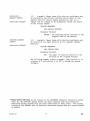
The following example of VCURSR allows the user the
capability of interactive line drawing. When a character
is struck, a line segment is drawn or a move is made from
the current beam position to the coordinates specified by
the graphic cursor.
* Not
supported on the 4006-1 Terminal.
4010A01 User
@
4-5
DIrENSION FRAI'I£ (8 )
DATA FRAI'E/l. , 0 . , 1 . , 1 .
C
C
*
*
lee
C
*
*
150
C
C 1:
C
C
CALL SWINDO(2S0.S00,lS0,500)
FRAME THE SCREEN WINDOW
CALL I'IOVEA(0. ,0. )
DO 100 I-l,,8,a
CALL DRAWA(FRAME(I),FRAMECI+l»
SAMPLE THE CURSOR REPEATEDLV
CALL AHMODE
CALL VCURSR<IBR.X,V)
A .p. IS STRUCK
IF(IBR.EQ.se)GO TO 200
A
MD- IS STRUCK
IF(IBR.EQ.68)GO TO 300
AN "M-
*
AN ·S· IS STRUCK
300
400
S00
,0. '"
CALL WINDO(e .. 1. ,0.,1. )
*
200
,e. , 1 . , e.
CALL INITT(120)
SPECIFY MINIMUMS AND EXTENTS OF WINDOWS
IS STRUCK
IFcIBR.EQ.77)GO TO 400
IFCIBR.EQ.83)GO TO see
GO TO lse
CALL POINTA(X,V)
GO TO 150
CALL DRAWA(X,V)
GO TO 150
CALL MOVEA(X,Y)
GO TO 150
CALL ANMODE
CALL FINITT(0.767)
END
I
n
TEK
Figure 4.6
4-6
@
4010A01 User
TERMINAL STATUS
AREA:
4.7
The Terminal Status Area is a set of variables which
are kept in a common block and represent the current state
of the Terminal. The Terminal Control System allows the
user to save the current Terminal status and return to it
at a later time.
Although it does not save the displayed data, this facility
does allow the user to interrupt his processing, move to
another location, do other processing there or interact
with the user, and then return to his original processing.
Since the user allocates the save areas, he may easily save
more than one level of status and may restore any of his
saved states at any time.
Subpoutine SVSTAT
4.7.1
The current status of the Terminal may be saved by
providing the status saving routine with a 60-word real
array in which the Terminal Status Area may be stored.
WARNING:
The status of dashed lines cannot be saved and
used again reliably.
CALLING SEQUENCE:
CALL SVSTAT (RARRAY)
Parameter Entered:
RARRAY - a 60-word real array.
Subpoutine RESTAT
4.7.2
The Terminal may be restored to any previously
saved state at any time by providing the status restoring
routine with the 60-word real array in which the previous
Terminal Status Area was stored.
CALLING SEQUENCE:
CALL RESTAT (RARRAY)
Parameter Entered:
RARRAY - the 60-word array containing
previously stored terminal state.
4010A01 User
@
4-7
CALL INITT( 30)
D I MENS I ON I BOX ( 8 ) " I T I ME ( 8 ) ~ B (60 ) • T ( 60 )
C
DATA IBOX/200.0,0.200.-200.e,0.-200/
DATA ITIME/80,0,-80,120,80.0.-80.-120/
CALL MOVABS(400.300)
SAVE CURRENT TERMINAL STATUS
CALL 5V5TAT(B)
CALL MOU~B5(460/340)
CALL S\..tSTAT( T ~
DO 100 N -1 , 7 " 2
CALL DRWRELlITIME(N',ITIME(N+l»
C
CALL St..'STAT (T )
RESTORE STATUS
CALL RESTAT(.B)
CALL DRWREL(.IBOX(N),IBOX(N+l»
CALL
S~)STAT ~
B)
100
CALL RESTAT(T)
C
OPTIONAL HARDCOPV
CALL HDCOPY
CALL FINITT(0,767)
STOP
END
Figure 4.7
4-8
@
4010A01 User
RESCALING A
GRAPHIC OUTPUT:
Subroutine RSCALE*
4.8
A graphic figure drawn with relative coordinates may
be rescaled by any virtual, relative factor which is compatible with the virtual window definition; that is, a
figure will be clipped if its dimensions exceed the limits
of the virtual window.
CALLING SEQUENCE:
CALL RSCALE (FACTOR)
Parameter Entered:
FACTOR - the rescaling factor relative to the
original size of the display.
ROTATING GRAPHIC
OUTPUT:
Subroutine RROTAT*
4.9
A graphic figure drawn with relative coordinates may
be rotated at any angle relative to its original display
position.
CALLING SEQUENCE:
CALL RROTAT (DEG)
Parameter Entered:
DEG - the angle of rotation relative to the
position of the original display.
The following example draws a triangle, then rescales it by
a factor of 2 and rotates it by 90° to obtain the second
triangle.
*
Those user's who have an old version of the TEKTRONIX Character Generation system
(Part No. 062-1494-00) should delete the above routines from their Character
Generation System software and use these subroutines in their place. The current
version of the 40l0A05 Plot 10 Character Generation System does not contain RSCALE
or RROTAT.
401 CA01 User
@
4-9
CALL INITTC30)
C
e
CALL TRIANC(200 .200.)
DOUPLE SCALE SI=E
CALL RSCALEl2 )
CALL RROTAT(90 )
ROTATED 90 DEGREES AND REDRAW
CALL TRIANG(700 ~400
CALL TINPUT(K)
CALL FINITT(10,10)
STOP
END
SUBROUTINE TRIANG(X.V)
CALL 1'10UEA(X. V)
CALL M('tJER( -100 ,-100.)
CALL DRAWR(200., 0. )
CALL DRAWR(-100 .. 200 )
CALL DRAWR(-100 .. -200 )
CALL POINTR(100 .• 100.)
PETURN
END
Figure 4.9
4-10
@
4010A01 User
Subpoutine RESET
4.10
This routine accomplishes the same function as
INITT (see Section 2.1), but it does not call for a new
page.
CALLING SEQUENCE:
CALL RESET
Subpoutine RECOVR
4.11
RECOVR updates the Terminal hardware to match the
Terminal Status Area variables. It is useful following
output to the Terminal which is outside the realm of the
Terminal Control System (e.g., a FORTRAN WRITE).
CALLING SEQUENCE:
CALL RECOVR
MISCELLANEOUS
UTILITY ROUTINES:
Subroutine HDCOPY
4.12
The user who is equipped with the TEKTRONIX
hardcopy unit appropriate to his terminal may have the
computer generate a hardcopy of the screen contents at
any time. This may be accomplished while in any mode and
does not affect the Terminal Control System status. The
system will prevent generation of additional output until
the hardcopy is completed.
CALLING SEQUENCE:
CALL HDCOPY
Subpoutine ERASE
The Terminal screen may be erased without changing the
mode or beam position. The Terminal Control System will
prevent generation of additional output until the erase
is completed.
CALLING SEQUENCE:
CALL ERASE
Subpoutine BELL
An audible tone may be output at any time to call the
user's attention to a particular event. Often a sustained
audible output, which may be generated by a series of calls
to the bell routine is used for an alarm. The "bell" may
be sounded while in any mode except GIN (Graphic Input)
mode and has no affect on Terminal Status.
CALLING SEQUENCE:
CALL BELL
4010AD1 User
@
4-11
Subroutine SEETW
Returns the current values of the screen window.
CALLING SEQUENCE:
CALL SEETW (MINX, MAXX, MINY, MAXY)
Parameters Returned:
MINX - the minimum horizontal screen coordinate.
MAXX
the maximum horizontal screen coordinate.
MINY
the minimum vertical screen coordinate.
MAXY
the maximum vertical screen coordinate.
Subroutine SEEDW
Returns the current values of the virtual window limits.
CALLING SEQUENCE:
CALL SEEDW (XMIN, XMAX, YMIN, YMAX)
Parameters Returned:
XMIN - the
the
XMAX
YMIN - the
the
YMAX
Subroutine SEEREL
minimum
maximum
minimum
maximum
horizontal user coordinate.
horizontal user coordinate.
vertical user coordinate.
vertical user coordinate.
Returns the values of the common variables used by the
relative virtual routines to scale and rotate vectors.
CALLING SEQUENCE:
CALL SEEREL (RSCOS, RSIN, SCALE)
Parameters Returned:
RCOS - the cosine of the rotation angle.
RSIN - the sine of the rotation angle.
SCALE- the multiplier used for scaling.
Subroutine SEETRN
Returns the value of the common variables set by the window
and transformation routines.
CALLING SEQUENCE:
CALL SEETRN (XFAC, YFAC, KEY)
Parameters Returned:
XFAC - the x scale factor
YFAC - the y scale factor
KEY - the transformation key
I
linear
2 - log
polar
3
4-12
REV A, OCT 1 980
4010A01 User
CONVERSION OF
INCHES TO SCREEN
UNITS:
Function KIN
4.13
The function routine KIN transforms inches to
screen units. It provides the number of raster units in
(RI) inches.
CALLING SEQUENCE:
Variable = KIN (RI)
Parameter Entered:
RI
- the number of inches.
Parameter Returned:
KIN
the number of raster units in
(RI) inches.
Example:
KIN is a means of determining a screen
position when the user wishes to work with
virtual units.
= KIN (1.4)
IX
CALL DRWREL (IX, 0)
CONVERSION OF
CENTIMETERS TO
SCREEN UNITS:
Function KCM
4.14
The function routine KCM transforms centimeters to
screen units. It provides the number of raster units in
(RC) centimeters.
CALLING SEQUENCE:
Variable
= KCM
(RC)
Parameter Entered:
RC
- the number of centimeters.
Parameter Returned:
KCM
the number of raster units in
(RC) centimeters.
Example:
KCM is a means of determining a screen
position when the user wishes to work
with virtual units.
IX
=
KCM (3.5)
CALL DRWREL (IX, 0)
401 OA01 User
@
4-13
MEASURING THE
WIDTH OF
CHARACTERS:
Function LINWDT
4.15
LINWDT provides the width in raster units as an
accurate measure of the horizontal size of a given number
of adjacent characters. The context is the current screen
coordinate system (1024 addressable points vs. 4096
addressable points).
CALLING SEQUENCE:
Variable
= LINWDT
(NUMCHR)
Parameter Entered:
NUMCHR
- the number of adjacent characters
for which the width in raster
units is desired.
Parameter Returned:
the width in raster units of
NUMCHR characters in the current
character size.
LINWDT
MEASURING THE
HEIGHT OF LINES:
Function LINHGT
4.16
LINHGT provides in raster units the accurate
measure of the height of a given number of lines.
CALLING SEQUENCE:
Variable
=
LINHGT (NUMLIN)
Parameter Entered:
NUMLIN
- the integer number of lines for
which the height in raster units
is desired.
Parameter Returned:
LINHGT
4-14
@
the height in raster units of
NUMLIN lines in the current
character size (see CHRSIZ,
Figure 5.3).
4010A01 User
TABS AND MARGINS
4.17
The Terminal Control System allows the user to
set and reset tabs and margins to facilitate format layout.
The tab and margin settings are software generated and as
such are useful only for A/N output through Terminal Control
System routines. All tab and margin values are in screen
coordinates. Both horizontal and vertical tabs and left and
right margins are available; both horizontal and vertical
tabs are limited to ten positions each.
SETTING THE TAB
TABLE:
Subroutine TTBLSZ
4.17.1
Tab settings for both horizontal and vertical
tabs are kept in two ten-word integer arrays. The settings
are ordered with ascending screen coordinates, the first
zero value indicating the end of the settings. TTBLSZ
sets up the size of the integer array. The horizontal and
vertical arrays must be equal in size.
CALLING SEQUENCE:
CALL TTBLSZ (ITBLSZ)
Parameter Entered:
ITBLSZ - the size of the tab table
(horizontal and vertical)
expressed as an integer
from 1 to 10.
TAB SETTING:
Subroutine SETTAB
4.17.2
The routine SETTAB takes a given tab setting in
screen coordinates and inserts it into the given tab table.
If the tab is full, the maximum setting will be lost in
order that a lessor tab setting may be inserted. Although
duplicate tab settings are not inserted, SETTAB does not
generally check the tab setting for validity nor does it
know whether the given tab table is horizontal or vertical.*
CALLING SEQUENCE:
CALL SETTAB (ITAB, ITBTBL)
Parameters Entered:
ITAB
tab setting in either X or Y
coordinates.
ITBTBL - the horizontal or vertical tab
table (Array Name).
* SETTAB expects ITBTBL to be initialized to zero. If the system does not do this
automatically, the user should do it with a DATA statement.
4010A01 User
@
4-15
REMOVING A TAB:
Subroutine RSTTAB
4.17.3
To remove a tab selectively, its position in
screen coordinates (ITAB) must be entered along with the
proper tab table. Non-zero values which do not coorespond
to a current tab setting are ignored. If the value of the
tab position is 0, the entire tab table will be removed.
CALLING SEQUENCE:
CALL RSTTAB (ITAB, ITBTBL)
Parameters Entered:
I TAB
- the X or Y screen coordinate of
the tab to be removed. If the
number is 0, all tabs in the tab
table designated will be removed.
ITBTBL - the horizontal or vertical tab
table (Array Name).
THE HORIZONTAL TAB:
Subroutine TABHOR
4.17.4
Calling the horizontal tab routine will cause the
alphanumeric cursor to be moved with a constant Y-value to
the position specified by the first non-zero entry in the
horizontal tab table, IHORZ, which is greater than the
current screen X-coordinate of the cursor or beam position.
If the horizontal tab table is empty, no action will occur.
If the tab table is not empty and no entry exists which is
greater than the current screen X-coordinate of the cursor
or beam position, or if the first non-zero entry greater
than the screen X-coordinate is also greater than the right
margin setting, a new line will be generated.
CALLING SEQUENCE:
CALL TABHOR (ITBTBL)
Parameter Entered:
ITBTBL - the name of the horizontal table.
4-16
@
4010A01 User
THE VERTICAL TAB:
Subroutine TABVER
4.17.5
Vertical tabbing will cause the alphanumeric
cursor to be moved with a constant X-value to the position
specified by the last non-zero entry in the vertical tab
table which is less than the current Y-coordinate of the
cursor on beam position. If no such entry exists, then no
action is taken.
CALLING SEQUENCE:
CALL TABVER (ITBTBL)
Parameter Entered:
ITBTBL - the name of the vertical tab table
(see SETTAB, Section 4.17.2).
The following example sets the tabs and resets them,
putting our characters with the help of subroutine ANCHO
(Section 4.3).
4010A01 User
@
4-17
DIMENSION IHORZ(4).IVERT(4)
CALL INITT (30)
CALL TTBLSZ (4)
CALL SETTAB <ae.IHORZ)
CALL SETTAB (S0,IHORZ)
CALL SETTA~ (aS0,IHORZ)
CALL SETTAB (400.IHORZ)
CALL SETTAB (750.IVERT)
CALL SETTAB (600, I~JERT)
CALL SETTAB (S00.IUERT)
CALL SETTAB (233.IVERT)
DO 10'" IUTAS-t . "
IF (It·TAB. EQ. 3) CALL RSTTAB (2S0, I HORZ )
IF lIVTAB EQ.3) CALL SETTAB (l50,IHORZ)
CALL TABVER <IVERT)
00 50 IHTAB-l . 4
CALL TABHOR (IHORZ)
LTR-6~+IHTA8+~*(IVTAB-l)
C.ALL ANCHO (LTR)
50
CONTINUE
CALL NEWLINE
1()~
CONTINUE
CALL FINITT (0,0)
END
A •
c
D
E F
G
H
I
J
K
L
Screen Limits
r1
tf
o
p
Figure 4.17
4-18
@
4010A01 User
SETTING THE
MARGINS:
Subpoutine SETMRG
4.17.6
This routine sets the left and right margins to
be used by Carriage Return (CARTN), HOME, and NEWPAG (see
Section 4.4).
CALLING SEQUENCE:
CALL SETMRG (MLEFT, MRIGHT)
Parameters Entered:
MLEFT
- the screen coordinate at which a
line of alphanumeric output starts.
Its value should always be greater
than 0 and less than the maximum
screen coordinate (1023 or 4095) or
the right margin value.
MRIGHT - the screen coordinate at which a
line of A/N output ends. Its value
should always be greater than MLEFT
and less than the maximum screen
coordinate (1023 or 4095).
LEVEL CHECKING:
Subpoutine TCSLEV
4.18
This routine returns the last date of modification
for the Terminal Control System as well as the level number.
CALLING SEQUENCE:
CALL TCSLEV (LEVEL)
Parameter Returned:
LEVEL
- a three element integer array where:
Level 1
Level 2
Level 3
4010A01 User
@
=
=
=
the year of modification.
the julian day.
the level number.
4-19
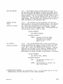
5.
ROUTINES WHICH SUPPORT THE 4014 or 4015 * TERMINAL
The following routines specifically support the 4014 Display
Terminal and the 4014/15 with the Enhanced Graphics Module.**
The Terminal Control System is compatible in its entirety
with the 4015/15 Terminal, but the special routines allow
the Terminal to utilize its extra capabilities.
The 4014/15 Enhanced Terminals have an addressable range of
points from 0 through 4095 on each axis, although its normal
range is from 0 through 1023 points. The address character
sequences used by both address ranges are compatible with
all TEKTRONIX Graphic Display Terminals; however, when using
the 4096 range of addressable points on the 4006, 4010, 4012,
or 4013 Terminals, the resolution is only to ever fourth
address point.
That a 4014 or a 4015 is being used, with or without the
Enhanced Graphics Module, is specified by the first parameter
of Subroutine TERM (Section 5.1).
IDENTIFYING THE
40Z4/Z5 TERMINAL:
Subroutine TERM
5.1
In order to take advantage of the extra features of
the TEKTRONIX 4014/15 Terminal, the user must inform the
Terminal Control System that he has the capability. He does
this by specifying his Terminal with Subroutine TERM. If he
does not use TERM before calling 4014/15 routines, the
Terminal Control System will treat his Terminal as a 4010 or
a 4012/13 Terminal. TERM needs to be called only once,
however, after each initialization (i.e., call to INITT).
CALLING SEQUENCE:
CALL TERM (ITERM, ISCAL)
Parameters Entered:
ITERM
ISCAL
- an integer from 0 to 3 where:
o - indicates 4006-1***
1 - indicates 4010, 4012/13
2 - indicates 4014/15
3 - indicates 4014/15 with
Enhanced Graphics Module
- either 1024 (addressable points)
or 4096 (addressable points)
* The 4015 Terminal and 4013 Terminal offer an APL character set as well as the
ASCII character set available on the 4014 and 4012 Terminals. The notation 4014/
15 refers to either the 4014 or the 4015 Terminal; the notation 4012/13 refers
to either the 4012 or 4013 Terminal.
** The Terminal Control System does not support Special Point Plotting for the
Enhanced Graphics Module.
*** Releases 3.0 to 3.3 of Terminal Control System may require modifications to
BAKSP for 4006-1 operation.
4010A01 User
@
5-1
MODIFYING THE
Z-AXIS OF THE
40Z4/Z5 TERMINAL:
Subroutine CZAXIS
5.2
Vectors on the 4014 or 4015 Terminal cannot only vary
in X and & position; they also vary in brightness and storage
properties. This type of variation is called the Z-axis
capability. The 4014/15 Terminal has three Z-axis capabilities
Normal Z-Axis - This is the same storage tube mode which is
available on the 4010 Terminal. The display
is bright and sharp. It is also stored on
the screen until it is erased by a call to
NEWPAG or ERASE (Sections 4.4 and 4.12).
Normal Z-axis is the default mode and is
used at all times unless a call to CZAXIS
is made.
Defocused Z-Axis - This mode is in all respects similar to
normal mode, except that the display is
results in broader lines and is slightly
brighter.
Enabled Write Through Mode - This mode allows a stored
display and refreshed information to coexist
on the Terminal screen. For example, the
user may wish to display a graph, yet add
moving vectors to the original graph. These
vectors must be refreshed.
CALLING SEQUENCE:
CALL CZAXIS (ICODE)
Parameter Entered:
ICODE - an integer from 0 through 3 calls
the Z-axis mode.
o-
normal Z-axis
1 - defocused Z-axis
2 - enabled write-through mode
5-2
@
4010A01 User
CHANGING THE
CHARACTER SIZE
ON THE 4014/15
TERMINAL:
Subroutine CHRSIZ
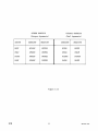
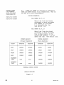
5.3
The 4014/15 Terminal has four different available
character sizes which range from a very small 133 characters
per line size to a very large 74 characters per line size.
CHRSIZ changes both the current character size and the
variables associated with the change. The default size is
size I (see below).
CALLING SEQUENCE:
CALL CHRSIZ (ICHAR)
Parameter Entered:
ICHAR
- an integer which has one of the
following values representing the
size of the characters.
CHARACTER SIZE
CHARACTERS/LINE
1
2
74
81
121
133
3
4
MEASURING THE SIZE
OF A CHARACTER:
Subroutine CSIZE
LINES/PAGE
35
38
58
64
5.4
CSIZE provides the current character height and width
in raster units. The characters are measured in the screen
coordinate system in use, either 1024 or 4096. This subroutine is useful for imposing alphanumeric characters on
graphic displays, primarily in the case of labeling. It
allows the user to see where his label ought to be placed
to coincide with grid lines and tic marks. When dealing
with the multiple character sizes available on the 4014
Terminal, this routine is especially helpful.
CALLING SEQUENCE:
CALL CSIZE (IHORZ, IVERT)
Parameters Returned:
IHORZ
- the horizontal character dimension,
including inter-character space;
the horizontal distance between
two periods.
IVERT
- the vertical distance, as above,
including interline spacing.
The following example demonstrates a use of CSIZE and
CHRSIZ. Subroutine ANCHO (Section 4.3) is used to output
the alphanumeric character.
4010A01 User
@
5-3
c
c
*
*
I:F~'1aNS1HATIOf\J
or CHLSI7. ANL, CSI?E
(;.H!J )
U~t, {:I SUti,OUIINl! 10 [,0 lHt. wOhK
CAL L 1 E EM (3, 1 0 ~ 4 )
CALL SUI:-l (~',4~i~"1)
(; PI.. L.
I NIT 1
CALL SUEI
CALL
(500,40~,~)
SUb 1
«(1,
'1,
~i)
CAL L S {j 1.3 1 (~) ('H~;, n, II )
CALL FI\lIIT (0,(~)
f.,N 1.1
C
*
*
*
L
*
L
L
~
LJbhO UT I N r.
AN~
10
~OSI1IO~
C HA~J (jE: A\J lJ ~:!~ASUhl<.. CHP.Et\C 1 EE S
I~f
O~l~~l
oSLJLhU LJl IN E .sUE 1 (I X, I Y, I CHhSZ)
UP 1HE lvtESSACiE .AI'.h~Y
Li Iiv; EX oS I O~'J 1>1 S G (:) 5 )
LA 1 P p.~ Sri 1 ( 7 , 7 2, (. ~, F.~ 2, (5, (7 , 8 LJ, (9, 8 2, 32, 8 3, 73, 9 (.1, f 9,
,v~
32, 7 3, 8 3, 3 2, (/), f", 3 2, 8 8, 32, 0, (), 3 2, 8 L,j, f 9, 75, 8 0, 79, '"I 3,
&
78, 8 4, 8 3, 44, (j, 0, 32, 8 8, 3 ~~, 0, (1, ~~ 2, .,." 7 ':..i, 7 R, '1 3, R G, 79,
.st.l
&
L~AW
73,78,84,83,4(1
OU1PUT
A bOX
FO~
CALL MOVAFS (TX,IY)
CALL DF:t·j BEL (310, (I})
CALL LRW~EL (0,310)
CALL
c
*
C PL L
~El
I.;hw BEL
Df1 WEEL
A~L
CP-LL
CALL
CAL L
(- 3 1 e, 0)
(0, - 3 1 0 )
M~ASUhE
CHA~PC1~~
SI~E
I~
409f SPACE
Tl! EM
(3, 409 (-,)
CHhSI Z (I CHESZ )
C S I Z. E (I H0 f. z., I \;1:, hi)
IMSG(37)=IHO~l/10+4~
IMSG(38)=IHOPZ-IHO~~/10*le+4A
IMSG(42)=I~Efl/10+~8
C
*
I r-" SG ( L; 3) = I \/f< f1 T- I \i E.f11 1 1 0* 1 0+ 4R.
~\l r. Ml=, P S LJ EtCH Ah .A C1 E F. 5 I Z F-, I N 1 0:2 Li S P Po C E.
oS E. '1
C tIL L
CALL
T f. EM
(3, 1 v.12 LJ )
eEESI Z (I CHl.SZ)
C S I Z E (I H 0 1(!-, I \; E h 1 )
CAL L
IMSG(19)=IHOhZ/10+48
I r-1 S G ( 20. )
=I It (J feZ -
I H0 liZ 1 1 ,~:+: 1 0+ ~ 8
IM5G(24)=I~FF1/10+~8
C
*
IMSG(25)=I~Ef11-IVt~1/10*10+qR
FOSITI00J ANL PUT OUT :1ESSAGE
CPLL
MO~ABS
(IX,IY)
CALL MO\EEL (20,200)
LO
100
1 fH0
1= 1, 1 5
CALL A!.\JCHO <IMSG(I»
CALL A"lCHO (I CHESZ+48)
=-
I 2L N L:'-J
2 * I v E F. T
CALL tlO\;EFL (-1 f-*IHObl, I
va 200 1= 1 (" :3 (
~vw
CP·LL AN CHO (It-i SG ( I ) )
CALL MOVhl!:L
DO
3 10
5-4
2L~~0~)
(-~l*IHOf.Z,
12L).JLN)
3 1 (2) . I = 37, 5 5
CAL L A\] CH 0
t:rJ 1 Uf.\J
~~J L
(I M S G ( I ) )
@
4010A01 User
CHARACTER SIZE 1
CHARACTER SIZE 2
IS 14 X aa
IS 13 X 21 TEKPOINTS
TEKPOINT~
51 X 83 MINIPO!NTS
56 X 88 MINIPOINTS*
CHARACTER SIZE 3
CHARACTER SIZE 4
IS S9·X 13 TEKPOINTS
IS
~8
34 X 53 MINIPOINTS
31
K
X 12 TEKPOINTS.
.a MI"IPOIHTS
Figure 5.4
* TEKPOINTS means addressable points in 1024 x 1024 space;
* MINIPOINTS means addressable points in 4096 x 4096 space.
4010A01 User
@
5-5
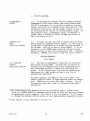
INCREMENTAL
PLOTTING:
Subroutine INCPLT
5.5
INCPLT is used to perform incremental plotting.
Each incremental plot character will move the beam one
raster unit in the given direction. The user specified
the direction, whether it is to be visible or invisible
and whether he wishes this plot character to be output.
The user must have a 4014 or 4015 with the Enhanced Graphics
Module and have specified a 4096 grid in his call to TERM
(Section 5.1).
CALLING SEQUENCE:
CALL INCPLT (IONOFF, IDIR, NO)
Parameters Entered:
IONOFF
o
Beam off (invisible)
Beam on (visible)
1
IDIR
Direction Code
NO
the number of times the plot
character is to be repeated.
Direction Code:
1
0
---*"--2
3
Figure 5.5
Example:
CALL
CALL
CALL
CHLL
CALL
C~LL
CALL
CALL
~ALL
CALL
CALL
END
5-6
@
INITT (30)
TERM (3.4096)
M0UABS .. 200 .' 200 )
INCPLT (1.0.300)
INCPLT (0.2.100)
INCPLT (1,4.300)
INCPLT (0,1.100)
INCPLT (1.S~300)
INCPLT (0.0.100)
INCPLT (1.8,300)
FINITT (0,0)
#=
401 OA01 User
CHECK TERMINAL
MODES:
Subroutine SEEMOD
5.6
SEEMOD returns the value of common variables indicating
the status of the hardware dashed line type, Z-axis mode,
and Terminal mode. (See Sections 3.12 and 5.2).
CALLING SEQUENCE:
CALL SEEMOD (LINE, IZAXIS, MODE)
Parameters Returned:
LINE
- the hardware line type in effect
IZAXIS- the hardware Z-axis mode
MODE
- the software mode:
o
alphanumeric
1 - vector
2
point plot
3
incremental plot
4
dash
CHECK TERMINAL:
Subroutine SEETRM
5.7
SEETRM returns the common variables which identify
terminal speed, type, character size, and the maximum
range of addressable points (4096 or 1024).
CALLING SEQUENCE:
CALL SEETRM (ISPEED, ITERM, ISIZE, MAXSR)
Parameters Returned:
4010A01 User
ISPEED
the baud rate in characters per
second which has been set in
INITT (Section 2.1).
ITERM
the terminal type set in TERM
(Section 5.1).
ICSIZE
the character size set in CHRSIZ
(Section 5.3).
MAXSR
the maximum screen address set
in TERM (Section 5.1).
@
5-7
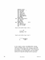
6.
TRANSFORMATIONS*
The transformation routines in the Terminal Control System
allow the user to define any of three coordinate systems;
linear, logarithmic, or polar. The default transformation
(LINTRN) is linear, and it remains in effect until one of
the transformations is called. LINTRN returns the user to
a linear window.
The logarithmic transformation, LOGTRN, allows the user to
express data as logarithms with reference to either the
X or Y-axis or both.
The polar transformation, POLTRN, allows the user to define
his coordinates as radius and degrees.
Each transformation occurs automatically before the drawing
of a vector; each remains in effect until another transformation routine is called or until the system is re-initialized.
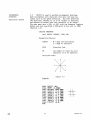
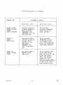
TRANSFORM:
Alter the coordinate system in which data is
specified.
Example:
POLTRN
radius, angle
l~,~o
LINTRN
X, Y
l~,~
1~,9~0
~,10
10,180 0
-10,~
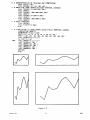
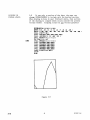
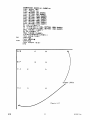
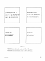
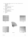
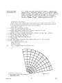
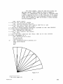
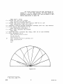
Figure 6, produced by the following codes, draws a grid by
means of a user-written subroutine, GRID**; this gridwork
is displayed in five different coordinate systems. Grid (a)
is linear. Grids (b), (c) and (d) demonstrate the three
different types of logarithmic transformations; respectively,
they are (log-x, linear-y), linear-x, log-y) and (log-x,
log-y). Grid (e) demonstrates a call to the polar transformation, POLTRN. All five grids use the same virtual
data. The difference between them is the result of the
transformation through which they are viewed.
* The 4010AOl PLOT 10 Terminal Control System, System Manual explains how the user
may write his own transformation routines by means of user hooks provided in
internal routines of the package.
** See page 55 for the coding of GRID.
4010A01 User
@
6-1
CALL INI1T(10.)
1 H r., [;t! T A t;)I N LO \,I)
lJtoJ r N LO ( 1 0., 1 00., 1 Q" . , 1(/';0. )
SChEE~
i.eI!N[,QW (P)
*
*
LEF INE
C
*
C
*
L.t-Aw A GJiIV SHOwI\J(l A LI~JI<P.l~
CALL Gl-<{ L
Lt,I<IN:t. ~Ch~E~ WI\)LO~ (b)
C
C
C
*
C
~
CtlLL
DF}<
I~r.
CALL
lWINDO(0,25~,500,7~e)
C/~L
1 tIl I ~! LJO (
CALL
LOGlh\)(l)
GhIL SHOwING A LOG-X. LI~JtAF-Y
Gf~I L
SCLfo,E',:'-J WI:'J LOW (C)
1 iN I \J DO ( 'I 5 0, 1 C-i 0 0. 50 e,. 7 50 )
LOGTfN(2)
l)hAw A
CALL
[FF I\iE
CtlLL
CALL
((1,
A
GhIn
Cf.LL
LIEf IN E,
CALL
CALL
CElLi
LOG 1 h\J ( 3)
1:
[·h~hl
GhIL
C
*
CAf-OL
LEI< INE
CPLL
C?\T-OL
C
*
C
C
C
*
*
lhA'\lSrOfMAlIOl'~
r.:f(~\..j
A
2 5 0, 0, 2 50 )
SHOWI~G
SC f; EEN
A
LINEA~-X,
ThANS}OOE~1ATIO~J
LOG-Y lkANSFOfiMA1I0N
WIN [,0 W (1; )
T WI ~ DO ( 7 S 0, 1 ('10 e"
SHO~I\)G
(1,
2 5 ~))
A LOG-X. LOG-Y
l~ANSrO~~ATION
GhIl!
SCfiEEN WI\)LOW (E)
T\'JINLiO( 375, f25. 250, 50C'·)
PO L T F"J ( 1 0. , 1'~ 0. , 0. )
L;l~AW
A G f1 I Ii SHO wIN G A FOL I\E T EA\J S r 0 FM AT r 0\1
l,ALL Gl\IL
CALL Fe I \J I 11 (0, 0)
r.:\) L
*
6-2
@
4010A01 User
C
*
DfiAW A
G~ID
WITH
LI~~S
~ROM
10 TO 100 AT
IN1Eh~ALS
OF 10
SUBhO lil I ~ E Gf> I lJ
LM IN= 10.
D~AX=10,"J.
X= L;M I ~
C
DR P> W G fl1 L LIN F!. S AL ON G X- AX I S
DO 1 (1 0 I = 1, 1 0
CALL MOVEA(X,LMI~)
CALL DBAWSP>(X,DMAX)
100
x=x+ 10.
¥= 10.
*
C
*
DRAW GElD
DO
LIN~S
ALONG Y-AXIS
200 J=1,10
CALL MOvEt\([lMI:'],Y)
CALL DE.A\.J SA ( DM AX, Y)
Y=Y+10.
200
BE:IUBN
E.NL
(a)
(c)
(e)
(b)
4010A01 User
Figure 6
@
(d)
6-3
THE LINEAR
TRANSFORMATION:
Subroutine LINTRN
6.1
LINTRN returns a user from either a logarithmic or
a polar window and establishes linear scaling. A linear
window is assumed for all Terminal Control System routines
until log or polar definitions are requested; it is,
therefore, not necessary to call LINTRN upon initializing
a program.
CALLING SEQUENCE:
CALL LINTRN
THE LOGARITHMIC
TRANSFORMATION:
Subpoutine LOGTRN
6.2
LOGTRN defines either the X or Y axis or both as
logarithmically scaled to fit the user's screen window.
The extent of the logarithmic definition is determined by
the parameter KEY.
NOTE
If the cuppent data window limits are not positive fop an
axis defined as Zogarithmic~ that axis will be peset to
linear to avoid an invalid tpansformation.
CALLING SEQUENCE:
CALL LOGTRN (KEY)
Parameter Entered:
KEY
1 - x-axis logarithmic
y-axis linear
THE POLAR
TRANSFORMATION:
Subroutine POLTRN
6-4
2
-
x-axis linear
y-axis logarithmic
3
-
x-axis logarithmic
y-axis logarithmic
6.3
POLTRN allows the user to define his virtual graphic
data to the Terminal Control System in polar coordinates.
Polar coordinates are specified by radius and angle. The
angle is represented in degrees, counter-clockwise from a
horizontal line to the right of the origin. The arguments
of POLTRN control the shape of the screen window in which
the virtual data is displayed. The virtual window is
scaled and transformed to fit into the screen area between
REV A, NOV 1980
401 OA01 User
arguments ANGMIN and ANGMAX. The third argument, RSUPRS, is
subtracted from the virtual radius. If ANGMIN and ANGMAX do
not equal the data window (DWINDOO minimum and maximum (YMIN
and YMAX), or if RSUPRS is not equal to zero, a distortion
of the virtual polar data will occur (see Figures 6.7 and
6.8). The user can adapt this distortion to emphasize any
features he wishes. The polar origin is automatically
located to obtain the largest possible display area within
the user's screen window.
CALLING SEQUENCE:
CALL POLTRN (ANGMIN, ANGMAX, RSUPRS)
Parameters Entered:
ANGMIN - the minimum angle relative to the
horizontal from which the display
will appear on the screen.
ANGMAX - the maximum angle relative to the
horizontal from which the display
will appear on the screen.
RSUPRS - the radius suppression factor.
DRAWING SEGMENTS
USING THE POLAR
TRANSFORMATION:
Subroutine DRAWSA
Subroutine DRAWSR
6.4
In order to draw the grid used in (e) of Figure 6,
a call to Subroutine DRAWSA was used in the construction
of GRID. This call was substituted for a call to DRAWA
(Section 3.5). DRAWSA is analogous to DRAWA, except that
it enables the user to draw the curved line segments that
are necessary when a polar transformation is in effect.
Subroutine DRAWSR is analogous to DRAWR (Section 3.6), but
again it is used for a polar transformation.
CALLING SEQUENCE:
CALL DRAWSA (X, Y)
Where X and Yare the virtual
coordinates to which the line
segments are drawn.
CALL DRAWSR (X, Y)
Where X and Yare the virtual
coordinates relative to the
current beam position.
4010A01 User
REV A, NOV 1 980
6-5
DRAWING DASHED
LINE SEGMENTS
USING THE POLAR
TRANSFORMATION:
6.5
DASHSA and DASHSR are analogous to Subroutines
DASHA and DASHR (Section 3.11), respectively. They too
are used for a polar transformation.
CALLING SEQUENCES:
Subroutine DASHSA
Subroutine DASHSR
CALL DASHSA (X, Y, L)
Where X and Yare the virtual
coordinates to which the dashed
line segment is to be drawn.
L is the dashed line type
(see Section 3.12).
CALL DASHSR (X, Y, L)
Where X and Yare the virtual
coordinates to which the dashed
line is drawn relative to the
current beam position. L is the
dashed line type. (See Section 3.12).
SCREEN GRAPHICS
(Integer Arguments)
ACTION
VIRTUAL GRAPHICS
(Real Arguments)
ABSOLUTE
RELATIVE
ABSOLUTE
RELATIVE
MOVE
MOVABS
MOVREL
MOVEA
MOVER
DRAW
DRWABS
DRWREL
DRAWA
DRAWR
POINT
PNTABS
PNTREL
POINTA
POINTR
DASH
DSHABS
DSHREL
DASHA
DASHR
SEGMENTED
DRAW
none
none
DRAWSA
DRAWSR
SEGMENTED
DASH
none
none
DASHSA
DASHSR
TERMINAL CONTROL SYSTEM
DRAWING ROUTINES
Figure 6.5
6-6
@
4010A01 User
6.6
Given the polar grid* (e) of Figure 6, examine the
capabilities of Subroutine POLTRN; the first example demonstrates a dashed line segment which connects thirty different
radii, with lengths between 90. and 100., at increments
of three degrees; they are displayed between an ANGMIN of
10° and an ANGMAX of 100°. Radius suppression is 0.
USING THE POLAR
TRANSFORMATION:
LIME-;\JSION kDATA(30)
8,
LA1A f.LA1A /90.3,92.4,94.5,95.2,9f.l,96.9,98.2,98.1,99.1,99.~,
99. 7, 1Vi Vi. 0, 9 9. 5, 99. ~1, 9 8. S, 9 R • (2), 9 7 • 5, 9 7 • (/\, 9 6. 5, 9 (,. v1 , 9 5. S, 9 S. 0,
& 94.0,93.0,92.0,93.0,97.0,94.3,91.0,92.8/
C
*
C
*
C
*
*
C *
C *
C
C
*
C ALL I:"J I T 1 (3 (2) )
L F. FIN E 1 H E 1 E h.1\1 I ~ AL WIN DO tv
CALL 1WI~DO(100,900,100,f00)
DEFINE THE DATA ~I~LOW WITH hALIUS F~OM 10 TO 100
CALL Dl.-JlNLO( 10., 1(~0., 1~", 100.)
SPE.C I fy A POL Ah IN I ~ DO~l DI SPL~Y ED BETtvEEN 10 AN D 1(10. DE GhEES
WITH RADIUS SUPPEESSION
CALL GHIL
1..,1
I 1 H INC h EM E:\J 1 0 F 3
CALL MOvEACEDATACl), 10.)
La 10 1= 1, 30
*
T· '. ~
*
ZEfiO
PLOl THE DATA STEPPING 1HE ANGLE }tRaM 10 10 100 DEGhEES
DEG EFE= 10+ I 3
r:OJ.I. T>ASHSA(hDATA(I
c. {. l~ L 1- I : r T -I ( :-., ,-. )
.~ 1 ( }.
10
O~
CALL POLlhNC10.,H~e.,0.)
DFtAW A GRID SHOViI01G THE \vINLOl.v
),r;EGFEf., 12)
I
Figure 6.6
See page 6-3 for the coding of
Subroutine GRID.
4010A01 User
@
6-7
The second example demonstrates how the same plot
would look if it were displayed with a virtual (data)
window with a radius between 90. and 100. Again the radius
suppression is 0. Notice that all grid lines specified
below 90. are clipped.
C
CALL INIll (30) *
LEF'Jl\l E THE IE F"'1 IN AL \aiI "J LOW
CALL 1 \.J I N LO ( 1 C e, 9 0 (3, 1 (10., E V) 0 )
* LE~I~~ THE DATA WI~DOW WITH fADIUS fRO~ ge 10 100
C AI. L L l.oJ I N 1'0 ( 9 0., 1 Vi 0 ., 1 (~., 1 0 0. )
SFECI~Y A FOLAR WINDn~ DISPLAYED BE1WEEN 10 AND 10C LEG2EFS
WITH EADILS SUPPkESSIO~ Of ZEEO
CALL POLTf,\]C 10., 100., (71.)
LhAW A GhIL SHOWI\JG THE WI0JDOIN
CALL GF11 D
* FLO T 1 H E, [, A1 A S 1 E, F PIN G TH E AN GL f· ~ h O;v1 1 0 1 0 1 0. 0 DE GEE F S
* i..J I T H I ~J C E EY C-J T 0 F 3
CAL L M0 \I E. A ( h DP-. T A ( 1 ), 1 0. )
DO 10 1= 1, 30
*
C
C
C
C
C
C
*
*
*
[. E G BE E= 1 0+ I
10
*3
CALL LASHSACf.uATACI ),lJ£GREE, 12)
CAL L r I N I 1 1 ( v.l, V'l)
:::']OF
ENL
.
--~
. . .'
..
Figure 6.7
*
6-8
The data and dimension statement which
precede INITT are the same as those of
Figure 6.6.
@
4010A01 User
The third example, using the same data points and
the same virtual (data) window as those of example 2
(Figure 6.7), demonstrates how the graph is displayed with
a radius suppression factor of 9~. from each of the thirty
radii, causing the data to be displayed between an ANGMIN
of 10 0 and an ANGMAX of 10~0 and between a radius minimum
of ~ and maximum of 1~.
C
*
CALL INTIT (30) *
DE Jt I N E TH E T E R"1 I N AL \.all N DO W
C
*
D~~IN~
C
*
*
C
C
*
*
C
*
C
10
lWINDO( 100,900, 100, E00)
1HE DATA WINDOW WITH hADIUS
CALL lJWINDO(90., 100., 10., 100.)
CALL
SFECIFY A FOLAR ~INDOW
F~O~
DISPLAYED BETWEEN
90 TO 100
10 AND
100 DEGFEES
WITH RADIUS SUPPRESSION Of 90
CALL FOLTEN( 10.,100.,90.)
DEAw A GraD SHOWING THE wINDOW
C.oLL GEl D
PLOT THE DATA STEPFI~G THE ANGLE rHO~
~) I TH INC REM ~'J 1 0 F 3
CAL L M0 vE. P. ( F; DA T A ( 1 ), 1 0. )
DO 10 1= 1, 30
DEGEEE= 10+ 1* 3
CALL DASHSA( f\DAT AC I ), DEGhEE, 12)
CAL L
10 TO
100 LEGFEES
FIN ITt ( 0, 0 )
STOP
ENL,
Figure 6.8
*
See note, page 6-8.
4010A01 User
@
6-9
The fourth example uses the same information as
example 3. In this case, however, the polar window is
displayed between an ANGMIN of 0° and an ANGMAX of 180°.
Radius suppression is again 90.
C
*
*
C
C
*
C
C
C
C
*
*
*
*
CALL
I~I'IT
(30)*
LEFIN E TH E 1 E. Ltv; p.,] AL
iN I N DO W
CALL TW IN DO ( 10ki1, 9 00, 100, (-'00)
DEfINE THE DATA WINLOW WITH EADIUS fBO~ 90 10 100
CAL L LW I N DO ( 9 0. , 1 0~)., 1 0., 1 0 0. )
SPECIFY A POLAR WINDOW DISPLAYED BET~EE~ ZERO AND 180 LEGfiEES
WITH hADIUS SUPPRESSION OF 90
C~..L L PO L 1 ftT\,J ( 0., 18 0. , 9 0. )
DRAW A GRID SHOWING THE WINDOW
CALL GkI D
PLOT THE DATA S1EPPING THE: ANGLE ffiOM 10 TO 100 DEGREES
IN I TH INC h EM EN 1 0 F 3
CALL MO vEA( BLA1 ~( 1), 10.. )
IJO 1 0 I 1, 3 0
=
lJEGhE,E= 10+ I * 3
CALL LASHSACFDATACI),DEGfEE,12)
10
C t-lL L
FIN I T 1 ( (",
v1)
STOF
f:-.NLJ
Figure 6.9
*
6-10
See note, page 6-8.
@
4010A01 User
7.
INPUT/OUTPUT ROUTINES
The user's program may perform three types of Input/Output
with Terminal Control System subroutines: graphic, alphanumeric, and Terminal/peripheral control. All the output
from the package routines is funnelled through the basic
subroutine, TOUTST, while all input comes in through subroutine TINSTR. The graphic and control I/O use these two
subroutines directly as well as their single character
counterparts, TOUPT and TINPUT. Alphanumeric I/O can be
accomplished through the more versatile set of routines
described below. The user should be aware that some of
the following routines may be implementation dependent (see
Implementation Notes).
For output the Terminal Control System translates all
characters to be sent to the Terminal into ASCII decimal
equivalent (ADE)* form and packs them into an output buffer.
When the buffer is full or the system or user calls subroutine TSEND, this buffer is dumped, translated into system
dependent code, and sent to the Terminal.
For input the Terminal Control System accepts system dependen
code received from the Terminal, translates it into ADE*
(see above) form, and distributes it to the subroutine
which called for it, if necessary translating it again into
alphanumeric format.
From the point of view of the user's program, alphanumeric
I/O may be accomplished more efficiently using direct
methods, such as FORTRAN READ and WRITE statements. However,
output through the Terminal Control System updates the
graphic beam position, except where noted, and allows control
over the exact positioning of characters anywhere on the
Terminal screen, while input through the Terminal Control
System provides correct formatting of data for later output
or internal processing. It is the user's responsibility
to call ANMODE to dump the output buffer before doing
FORTRAN I/O. (See RECOVR, Section 4.11). Positioning of
mixed FORTRAN and Terminal Control System output is
implementation dependent. See Section 7.11.1 for details.
* ADE code is simply the integer representation of the ASCII character set. The
ADE characters are the numbers from 0 to 127, with 48 representing 0, 65 "A",
90 "Z", etc.
401 OA01 User
@
7-1
Three formats are allowed for both input and output:
1.
2.
3.
OUTPUT:
Subroutine TOUTST
ADE (ASCII decimal equivalents)**
Al (where Al represents one word with one
alphanumeric character in it)
Am (where Am represents one word with m
alphanumeric characters in it. M is usually
the number of alphanumeric characters that
one word can contain)
7.1
TOUTST outputs an array of ADE* characters. This
routine does not update the graphic beam position within
the Terminal Control System, nor does it put the Terminal
in alphanumeric mode. TOUTST should be used only when
outputting control characters which are not otherwise
handled by the Terminal Control System.
CALLING SEQUENCE:
CALL TOUTST (NCHAR, IARRAY)
Parameters Entered:
Subroutine
TOUTPT
NCHAR
the length of IARRAY, i.e., the
number of characters to be output.
IARRAY
the array containing ADE characters
to be output.
7.2
TOUTPT outputs a single ADE* character. This
routine does not update the graphic beam position within
the Terminal Control System, nor does it put the Terminal
into alphanumeric mode. TOUTPT should be used only when
outputting a control character which is not otherwise
handled by the Terminal Control System.
CALLING SEQUENCE:
CALL TOUTPT (ICHAR)
Parameter Entered:
an ADE* character to be output.
I CHAR
Subroutine
ANCHO
7.3
ANCHO outputs a single ADE* character. This routine
places the Terminal in alphanumeric mode, outputs the
character, and then updates the position of the beam. For
a complete description of ANCHO see Section 4.3.
* ADE code is simply the integer representation of the ASCII character set. The
ADE characters are the numbers from 0 to 127, with 48 representing 0, 65"A" ,
90 "Z", etc.
** An ASCII decimal equivalent chart may be found at the end of this manual.
7-2
@
4010A01 User
CALLING SEQUENCE:
CALL ANCHO (ICHAR)
Parameter Entered:
I CHAR
Subroutine
ANSTR
the non-control ADE character
to be output.
7.4
ANSTR accomplishes the same function as ANCHO, except
that it outputs an array of non-control ADE characters.
ANSTR also places the Terminal in alphanumeric mode and
updates the graphic beam position within the Terminal
Control System. For complete description of ANSTR see
Sections 4.3 and 4.3.1.
CALLING SEQUENCE:
CALL ANSTR (NCHAR, IARRAY)
Parameters entered:
Subroutine
AlGUT
NCHAR
the number of characters to
be output.
IARRAY
the array containing the ASCII
decimal integer equivalents
for the characters to be output
7.5 AlOUT outputs an array of Al FORTRAN format characters.
This routine puts the Terminal in alphanumeric mode and
updates the graphic beam position in the Terminal Control
System.
CALLING SEQUENCE:
CALL AlOUT (NCHAR, IARRAY
Parameters Entered:
Subroutine
AGUTST.
4010A01 User
NCHAR
the length of IARRAY; the
number of characters to be
output.
IARRAY
the array of Al FORTRAN format
characters to be output.
7.6
AOUTST outputs an array of Am format characters. In
this format m represents the number of alphanumeric characters in one word. This routine also updates the graphic
beam position in the Terminal Control System.
@
7-3
CALLING SEQUENCE:
CALL AOUTST (NCHAR, IARRAY)
Parameters Entered:
INPUT:
Subroutine TINSTR
NCHAR
the number of characters to
be output, m times the length
(number of words) of IARRAY.
IARRAY
the array of Am format characters
to be output. If IARRAY is
shorter than NCHAR, it is padded
with blanks.
7.7
TINSTR accepts input from the Terminal and puts it
into an ADE array. These character- are in a form ready
to be output by ANCHO (Sections 4.3) or ANSTR (Section 4.3.1).
CALLING SEQUENCE:
CALL TINSTR (LEN, IARRAY)
Parameter Entered:
LEN
the number of characters
expected. If fewer than LEN
are received, IARRAY is padded
with blanks, and if more than
LEN are received, the next
call to TINSTR will input the
excess characters.
Parameter Returned:
IARRAY
Subroutine TINPUT
7.8
the ADE array into which the
input characters are placed.
TINPUT accepts one ADE character from the Terminal.
CALLING SEQUENCE:
CALL TINPUT (ICHAR)
Parameter Returned:
I CHAR
7-4
@
the ADE character received from
the Terminal. Since TINPUT
calls TINSTR, a null record
(entering only a carriage return
at the Terminal) becomes a
blank, while more than one
character entered is stored for
later access by any call to
TINSTR.
4010A01 User
Subroutine A1IN
7.9
AIIN accepts an array of characters from the Terminal
in integer Al FORTRAN format. The array is in the correct
format to be output by subroutine AlOUT (Section 7.5)
CALLING SEQUENCE:
CALL AIIN (NCHAR, IARRAY)
Parameter Entered:
NCHAR
the number of characters expected
from the Te\minal. Since AIIN
calls TINSTR (Section 7.7) if
fewer than NCHAR characters are
received, IARRAY is padded with
blanks; if more characters than
NCHAR are received, they are
stored for later access by any
call to TINSTR.
Parameter Returned:
IARRAY
Subroutine AINST
the array in which the Al format
characters are placed.
7.10
AINST accepts an array of characters from the
Terminal in Am format. This array can then be output by
subroutine AOUTST (Section 7.6).
CALLING SEQUENCE:
CALL AINST (NCHAR, IARRAY)
Parameter Entered:
NCHAR
the number of characters expected
from the Terminal. Since AINST
calls TINSTR (Section 7.7), if
fewer than NCHAR characters are
received, IARRAY is padded with
blanks; if more than NCHAR are
received, they are stored for
later access by any call to TINSTR.
Parameters Received:
IARRAY
4010A01 User
@
the array in which the Am format
characters are placed.
7-5
Utility I/O
Routines
7.11
The following routines aid the user of the Terminal
Control System in outputting or inputting data. These
routines, however, should be used carefully and in most
cases will not need to be called.
Setting the
Output Buffep
Format:
Subroutine SETBUF
7.11.1 The user will find it necessary to control his
output format after implementation of the package only
when changing to a different Terminal type (e.g., from a
4010 to a 4014) or when transferring to a different
computer system. The output format must be changed in
these cases in order to avoid interline character problems
(see the Implementation Notes). Interline characters,
particularly carriage return (CR), line feed (LF), and
timing characters (NUL or SYN), need to be suppressed to
make graphic input possible. If the user's implementation
doesn't suppress interline characters, the user will need
to call SETBUF as well as TERM when chaging from a 4010 or
4012 Terminal to a 4014 Terminal.
CALLING SEQUENCE:
CALL SETBUF (KFORM)
Parameter Entered:
the format of the output buffer, after
the following code:*
KFORM
1 -
For 4010 and 4012 Terminals. This
format is for systems on which interline
characters cannot be suppressed.
Characters necessary to generate a move
back to the current beam position are
stored at the beginning of each buffer.
Graphic cursor input is not possible.
With buffer Type 1, the move back to the
current stored beam position happens
before every Terminal Control System
buffer output. For example, CALL CHRSIZ
(2). CALL ANMODE moves the alphanumeric
cursor to the location at which it was
after the previous buffer was transmitted.
The subsequent system-supplied interline
characters may move the cursor to the
left and down one line, so any nonTerminal Control System output that
follows will begin there.
* The following discussion is important for users who:
(a) Wish to mix Terminal Control System output with other types of output
(e.g., FORTRAN).
(b) Wish to run programs on different computer systems, or
(c) Wish to change Terminal types (e.g., from a 4012 to a 4014 Terminal).
7-6
@
4010A01 User
2 -
For 4014 Terminals. This format
is for systems on which interline
characters cannot be suppressed. Thus
interline characters follow each output buffer transmission to the Terminal.
However, a flag character (ESC) is sent
where necessary, and the 4014 hardware
ignores the interline characters. Graphi
cursor input is possible. In all other
respects Buffer Types 1 and 2 are identical, including their behavior when nonTerminal Control System output is mixed
with Terminal Control System output.
3 -
Used for all Terminals on systems
where interline characters may be
suppressed. Graphic cursor input is
possible. With Buffer Type 3, no
carriage returns or other interline
characters are appended to Terminal
Control System output by the computer.
All output begins at the position of
the alphanumeric or graphic cursor on
the Terminal screen. This position
agrees with the stored beam position
even after ANMODE or TSEND is called.
However, non-Terminal Control System
output causes a discrepancy between
the stored and the actual beam position.
4 -
Like Buffer Type 3, except that
output is unbuffered; i.e., each call
to TOUTST results in direct output.
Example:
A program follows to illustrate the Buffer Type dependent
results that occur when FORTRAN and Terminal Control System
output are mixed.
NOTE
Buffer types land 2 are not available
in the TSO version of the Terminal
Control System.
401 DAD1 User
@
7-7
DIMENSION ITHE(l)
DATA ITHE/5HTHE
/
CALL INITT(39J)
CALL SETBUF(2)
CALL TERM(3,1024)
CALL CHRSIZ(l)
CALL MOVABS(0,450)
CALL DRWABS(100,450)
CALL ANMODE
WRITE(5,100)
109.1 FORMAT(lX,9HTEKTRONIX)
CALL CHRSIZ(2)
CALL ANMODE
WRITE(5,200)
209.1 FORMAT(lX,15H
CALL CHRSIZ(3)
CALL AOUTST(5,ITHE)
CALL FINITT(0,200)
END
4014)
Results with Buffer Types 1 and 2:
_ _ _ _ TN!
TEKTRONIX
4014
Results with Buffer Types 3 and 4:
TEKTRONIX
THE
4014
On this computer system, the FORTRAN WRITE carriage
control character "space" (IX) results in a line feed
(LF) before FORTRAN output and a carriage return (CR)
after output. A carriage return and a line feed follow
each Terminal Control System output. On your computer
system results of this program may differ from those
shown due to different carriage control characters.
7-8
REV A, MAR 1980
4010A01 User
Detailed Explanation of the Example:
PROGRAM STEP
PLACEMENT OF OUTPUT
Buffer Type 1 and 2
Buffer Type 3 and 4
MOVABS (0,450)
DRWABS (100,450)
ANMODE
WRITE "TEKTRONIX"
Interline characters
following ANMODE and
the LF preceding
"TEKTRONIX" place
"TEKTRONIX" two lines
below (100,450).
The line feed
preceding "TEKTRONIX"
places it one line
below (100,450).
CHRSIZ (2)
ANMODE
WRITE "4014"
The software MOVE to
(100,450) and similar
carriage control
characters to the
above place
"TEKTRONIX" and
"4014" on the same
line.
The CR following
"TEKTRONIX" and the
LF preceding "4014"
place "4014" beginning
at the left margin two
lines below (100,450).
CHRSIZ (3)
AOUTST (5,ITHE)
FINITT
The software MOVE to
(100,450 places
"THE" there.
The CR following "4014"
places "THE" on the
same line as "4014" but
at the left margin.
NOTE: The software
assumes the cursor
position to agree with
the stored beam position.
No MOVE to the stored
beam position occurs.
4010A01 User
@
7-9
Examine the
Output Format:
Subroutine SEEBUF
7.11.2 SEEBUF allows the user to examine the format of
his output buffer (see SETBUF, Section 7.11.1).
CALLING SEQUENCE:
CALL SEEBUF (JFORM)
Parameter Returned:
the output buffer format presently
in use. For a 4010 or 4012 Terminal
JFORM should return either 1 (for
systems which do not allow interline
characters to be suppressed) 3, or
4 (for systems where interline characters may be suppressed). For a 4014
Terminal JFORM should return 2, 3 or 4.
JFORM
Examining the
UseabZeJ Space
in the Input
or Output Buffer:
Function LEFTIO
7.11.3 LEFTIO returns the number of characters remalnlng
in the Input buffer on the amount of space (in characters)
remaining in the Output buffer. In cases where the amount
of input is variable, for example, the user may wish to
see how many characters need to be processed before a
given input.
CAtLING SEQUENCE:
K=LEFTIO (IBUFF)
Parameter Entered:
indicates which buffer is to be
examined.
IBUFF
1
Input buffer
buffer
o Output
Parameter Returned:
the number of characters left in
the buffer indicated by IBUFF.
K
7-10
@
401 DA01 User
Locating the
Posi tion of the
Graphic Beam:
Subroutine SEELOC
7.11.4
SEELOC allows the user to locate on the screen
the last position of the graphic beam if he has generated
output outside the Terminal Control System (e.g., a FORTRAN
READ or WRITE or a call to TOUTST or TOUTPT (Sect'ions 7.1
and 7.2, respectively). Thus, he may update the beam
position himself.
CALLING SEQUENCE:
CALL SEELOC (IX, IY)
Parameters Returned:
Dumping the
Output Buffer:
Subroutine TSEND
IX
the screen X-coordinate of the beam.
IY
the screen Y-coordinate of the beam.
7.12
TSEND dumps the output buffer constructed by the
Terminal Control System output routines. Whenever the
output buffer becomes full, it is transmitted; but TSEND
may be called any time the user wishes to have all stored
output displayed. (It is customary to call ANMODE, as
TSEND may leave the Terminal in graphics mode.)
The positioning on the Terminal screen of non-Terminal
Control System output (such as a FORTRAN WRITE) is
dependent upon the way in which the software package is
implemented on your computer. See Section 7.11.1 for
details. If all output is through the Terminal Control
System, no such implementation dependencies exist.
CALLING SEQUENCE:
CALL TSEND
4010A01 User
@
7-"
APPENDIX A
I.
An Advanced Use of the Terminal Control System:
A2
Circuit Drawing
II.
Terminal Control System
Common Variables
III.
4010A01 User
Glossary
A7
A9
@
A-1
The combination of simple Terminal Control System routines
can result in sophisticates usages. The following example
demonstrates how the graphic cursor can be used in combination with simple moves and draws to create electrical
circuit drawings interactively.
The main program calls the virtual cursor. The user can
position it anywhere on the screen and, by punch different
Terminal keys, move and draw or call subroutines which
draw symbols at that position.
*
PROGRAM TO DRAW CIRCUITS INTERACTIVELV
DATA IDRAW/68/,IMOVE/77/,IERASE/S9/,IQUIT/81/,IHCOPY/72/
DATA IRESIS/8c/,ICAP/S7/,ITRANS/84/,IGRNO/71/
CALL INITT(30)
C
SET TERMINAL SCREEN WINDOW
CALL TWINDO(0/1000,0,750)
C
SET UIRTUAL SPACE DATA WINDOW
CALL DWINDO( 0 .. 500. ,0 .. 375. )
CALL MOUEH(0. ,0. )
C
CALL FOR THE GRAPHIC CURSOR
100
XFRON-XTO
VFROM-YTO
105
CALL UCURSR(KEY,XTO,VTO)
IF(KEY NE IDRAW)GO TO 110
CALL DRAWA(XTO.YTO)
GO TO 100
11 e
IF n(E'r' NE IMOVE )GO TO 120
CALL MOVEA(XTO,YTO)
GO TO lee
120
IF(~EYNE.
IE~ASE)GO TO 130
CALL ERASE
GO TO leS
130
IF(KEY .NE. IQUIT)QO TO 140
CALL FINITT(0.0)
140
IF(KEY HE IHCOPY)GO TO 150
CALL HDCOP',
GO TO 105
C
DETERMINE ROTATION OF SYMBOL
150
RANGLE-ATAN2(YTO-YFROM.XTO-XFROM)*57.2957795131
CALL RROTAT(RANGLE)
IF(KEY .NE. IRESIS)GO TO 160
CALL RESIST
CAll DRAWA(XTO,YTO)
GO TO 100
160
IF(KEY .NE ICAP)GO TO 170
CALL CAP
CALL DRAWA(XTO.YTO)
GO TO 100
170
IFCKEYNE. ITRANS)GO TO 180
CALL TRANS
CALL MOUEA(XFROM.YFROMl
C
BEHM LEFT AT START POINT FOR TRANSISTOR
GO TO 105
180
IFiKEY .NE. IGRND)GO TO 100
C
*
*
*
*
*
Ct4LL
C
A-2
*
GROUr~D
CALL MOUEA(XFROM.YFROM)
BEAM LEFT AT START POINT FOR GROUND SYMBOL
GO TO 10S
EHD
@
4010A01 User
The subprograms draw four different symbols:
Symbol
C
*
c
*
Keyboard Character
regis tor
R
capacitor
C
transistor
T
ground
G
ROUTINE TO DRAW A RESISTOR
SUBROUTINE RESIST
CALL DRAWR(10 .. 0 )
CALL DRAWR(3 .. 10.)
CALL DRAWR(S. ,-20. )
CALL DRAWRCS .20. )
CALL DPAWR(S. ,-20 )
CALL ORAWR~6 .. 20 )
CALL ORAWR(6. ,-20 )
CALL DRAWRC3 .. 10 )
RETURN
END
SUBROUTINE TO DRAW A CAPACITOR
SUBROUTINE CAP
CALL DRAWR(10 .. 0. )
CALL MOVER(0 .. 20.)
~ALL
C~LL
C~Ll
DRAWR(0 .. -40. )
MOUER(10 ,40.)
DRAWR(0 ,-40.)
CALL MOUER(0 ,20.)
RETURN
END
C
*
ROUTINE TO DRAW A TRANSISTOR
SUBROUTINE TRANS
CALL DRAWR(20 .. 0 )
CALL DRAWR(0. ,20. )
CALL DRAWR(2 ,0)
CALL DRAWR(0 .-40.)
CALL DRAWR(-2 .. 0. )
CALL DRAWR(0 ,20.)
CHLL MOUER(2. ,10.)
CALL DRAWR(20 .. 20. )
CALL MOUERC-a0 .. -40. )
CALL DRAWR(1S .. -15. )
CALL DP~WR(2. ,2. )
CRLL DRAWR(3. ,-7.)
CALL DRAWR(-7. ,3.)
CALL DRAWR(2.,2 )
CALL MOVER(S .. -5.)
-(
RETURt~
EnD
4010A01 User
@
A-3
C
*
ROUTINE TO DRAW A GROUND 5V,..80L
SUBROUTINE GROUND
CALL DRAWR( 10. ,0. )
CALL ~OUER(0. _-16. )
CALL DRAWR(0.,32.)
CALL MOVER(S. ,-27.)
CALL DRAWR(0.,22.)
CALL MOVER(S.,-17.)
CALL DRAWR(0.,12.)
CALL MOVER(S. ,-7. )
CALL DRAUR(0. ,2. )
RETURN
END
Examples of circuits which can be drawn using the
above program:
A transistor amplifier
A-4
@
4010A01 User
~----.-------~~---------------.----------Vcc
-•
A logic gate
4010A01 User
REV. A, MAR. 1978
A-5
II.
TERMINAL CONTROL SYSTEM COMMON VARIABLES
All functions and subroutines which required users of earliest releases (Release
2.0 and 2.1) of the Terminal Control System to access the /TKTRNX/ common area
are now supported by routines; therefore, conversion of programs which used earliest
releases TCS is fairly simple. The conversion consists of deleting the /TKTRNX/
common area from these programs and changing the code lines which set the common
variables, so that the appropriate subroutines are called, as follows:
Variables in /TKTRNX/ common
Subroutines in Release 3 or Levell
TRSINF, TRCOSF
TRSCAL
KLMRGN, KRMRGN
RROTAT
RSCALE
SETMRG
The tab routines are now somewhat different that in earliest versions (Release
2.0 or 2.1) in that ·no tab tables are provided in the common area. The user
must insert a dimension statement for KHORZT and KVERTT in his older programs
using the tab routines.
A list of TCS common variables follows.
A-6
@
4010A01 User
VARIABLE NAMES IN ALPHABETICAL ORDER
Name
Use
Description
KBAUDR
KBEAMX
KBEAMY
KDASHT
KEYCON
KFACTR
KGNFLG
KGRAFL
KHOMEY
KHORSZ
KINLFT
KKMODE
KLINE
KLMRGN
KMAXSX
KMAXSY
KMINSX
KMINSY
KMOFLG
KMOVEF
KOTLFT
KPAD2
KPCHAR
KRMRGN
KSIZEF
KTBLSZ
KTERM
KUNIT
KVERSZ
KZAXIS
TIMAGX
TIMAGY
TMAXVX
TMAXVY
TMINVX
TMINVY
TRCOSF
TREALX
TREALY
TRFACX
TRFACY
TRPARI
General
Screen Graphics
Screen Graphics
Virtual Graphics
Virtual Graphics
Screen Graphics
General
General
General
A/N
A/N
General
Virtual
Virtual
Virtual
Virtual
Virtual
Virtual
Virtual
Virtual
Virtual
Virtual
Virtual
Virtual
Characters per Second
Beam X-coordinate
Beam Y-coordinate
Dash Specification
Transformation Key
Addressing Factor
General Error Flag
Graphic Level Flag
Home Y-Value
Character Horizontal Size
Characters Left in Input Buffer
Mode
Vector Type
Left Margin
Screen Window Maximum X
Screen Window Maximum Y
Screen Window Minimum X
Screen Window Minimum Y
Future Expansion
Move Flag
Characters Left in Output Buffer
Padding Size
Previous Plot Characters
Right Margin
Character Size
Tab Table Size
Type of Terminal
Output Buffer Format
Character Vertical Size
Vector Intensity
Imaginary Beam X
Imaginery Beam Y
Virtual Window Maximum X
Virtual Window Maximum Y
Virtual Window Minimum X
Virtual Window Minimum Y
Relative Vector Cosine Factor
Real Beam X
Real Beam Y
Transformation Parameter
Transformation Parameter
Transformation Parameter
TRPAR6
TRSCAL
TRSINF
Virtual Graphics
Virtual Graphics
Virtual Graphics
401 OA01 User
I/O
General
Graphics
A/N
Virtual Graphics
Virtual Graphics
Virtual Graphics
Virtual Graphics
Unused
Screen Graphics
I/O
General
Screen Graphics
A/N
A/N
A/N
General
I/O
Graphics
Graphics
Graphics
Graphics
Graphics
Graphics
Graphics
Graphics
Graphics
Graphics
Graphics
Graphics
Transformation Parameter
Relative Vector Scale Factor
Relative Vector Sine Factor
@
A-7
III.
TERMINAL CONTROL SYSTEM
Glossary
ABSOLUTE VECTOR
A directed line segment from a given starting point to a
given end point. In screen graphics, the start point is
defined by the beam position, and the end point is an
absolute screen coordinate. In virtual graphics the start
point is the virtual beam position and the end point is
an absolute virtual coordinate.
ADE
ASCII decimal equivalent. The integer representation of
the ASCII character set. (See ASCII Code Chart.)
ALPHANUMERIC
CURSOR
A rectangular, non-stored, moveable marker which indicates
the next position at which a character will be displayed.
ALPHANUMERIC
MODE
The Terminal mode in which ASCII output will be interpreted
as characters to be displayed.
A/N
Abbreviation for "alphanumeric."
ASCII
American Standard Code for Information Interchange: A
standard code consisting of 7-bit elements for information
interchange among data processing communications systems.
BUFFERING
Storing input or output in an array (in the Terminal
Control System an array of 72 characters) which is transmitted or dumped when it is full or when a command to dump
is given.
CLIPPING
The modification of virtual graphics vectors so that the
portion of those vectors which lies outside of the virtual
window will not be displayed on the screen.
COORDINATE
An ordered pair (X, Y) of numbers uniquely represent a point
either on the screen or in virtual space. The ordered pair
of numbers used in the normal coordinate system (Cartesian
coordinates) represent the point according to its distance
from the origin (0,0) along the X and Y-axis respectively.
CURSOR
A-8
A moveable marker used as a reference.
@
4010A01 User
DEFOCUS MODE
Causes broader lines in the screen display; for the
4014/15 Terminal.
DRAW
The display command which causes a bright vector to
appear.
ERASE
The procedure of clearing the Terminal screen.
GRAPHIC CURSOR
A cross-hair cursor used to specify positional input.
Not available on the 4006-1.
HARDCOPY
A permanent copy of a display on the Terminal screen
which is made by a remote hardcopy unit.
HOME POSITION
The upper-left corner screen location at which the
first character of a page is normally printed.
INPUT
Data sent from the Terminal to the computer.
data provided to a subroutine.
KEYBOARD
The portion of the Terminal which allows the user to
enter A/N data into the computer.
LEFT MARGIN
The screen X-coordinate which represents the starting
position of a line of alphanumeric output.
LEVEL" RELEASE
Tes was available in Releases 2.0 and 2.1, 3.0 to 3.3
and Level 1 at the date of this printing.
MOVE
The display command which causes a dark vector to be
drawn.
NEW LINE
The operation which causes the alphanumeric cursor to
go to the left margin and down one line.
NEW PAGE
The operation which erases the screen and moves the
alphanumeric cursor to the HOME position.
ORIGIN
The coordinate represented by (0,0). The orlgln of
the screen is located at the lower-left corner.
Virtual space, by definition, has its origin at its
center.
4D1DAD1 User
@
Also,
A-9
POINT
The display command which causes a point to be drawn.
RASTER UNIT
The distance between two adjacent points on the screen;
the basic resolution element of the Terminal.
REFRESH
To renew a display. If a Terminal (i.e., a 4014/15
Terminal) is in non-store mode, this display must be
refreshed by the user's program to remain visible.
RELATIVE VECTOR
A means of describing an absolute vector which is drawn
relative to the current beam position.
RIGHT MARGIN
The screen X-coordinate which represents the rightmost
limit of alphanumeric output. Any attempt to write to
the screen beyond the right margin using an A/N output
routine will cause a NEW LINE to be generated.
SCREEN
The portion of the Terminal on which output from the
computer is displayed.
SCREEN
COORDINATES
The set of points which constitutes the screen. These
points form a discrete two-dimensional space and range
from (0,0) to (1023, 1023) inclusive; the 4014/15 Terminal
with Enhanced Graphic Module offers in addition a range
from (0,0) to(4095 to 4095) inclusive. SCREEN COORDINATES
MUST ALWAYS BE INTEGERS.
SCREEN WINDOW
The section of the screen into which the virtual window
is scaled and translated.
SOFTWARE
The programs and routines used to operate a computer.
STORAGE BEAM
The electron beam which is directed by the output to
draw characters and vectors on the Terminal Screen
STORAGE TUBE
A cathode ray tube (CRT) which will maintain a display,
once written, for an indefinite period until an erasure
is made.
TERMINAL
A console which accepts data from or sends data to a
computer. The term is used here with reference to a
TEKTRONIX 4006-1, 4010, 4012/13 or 4014/15 Display Terminal.
A-10
@
4010A01 User
TERMINAL STATUS
The current state of the Terminal.
TERMINAL STATUS
AREA
The set of common variables which represent the current
Terminal status.
TIMESHARING
The use of a computer to serve a number of individuals
in an essentially simultaneous fashion. Communication
with a timesharing computer is usually through an
interactive terminal.
TRANSFORMATION
The relationship between the virtual and screen windows.
It may include a scaling, a translation, and/or a change
of coordinate systems.
USER COORDINATES
A coordinate system in which the units of measurement
are defined by the user. See virtual Coordinates.
VECTOR
A line segment. A vector may be either bright (visible)
or dark (invisible). The former is generated by a DRAW
routine, the latter by a MOVE routine.
VIRTUAL
COORDINATES
The set of points which constitute virtual space.
VIRTUAL CURSOR
Allows the user to locate coordinates in virtual space
with the graphic cursor.
VIRTUAL SPACE
A user-defined, data-structured display area which is
Terminal independent.
VIRTUAL WINDOW
The portion of virtual space which is displayed in the
Terminal area defined by the screen window. Only that
portion of virtual space which is contained in the
virtual window will be displayed.
WRITE-THROUGH MODE
Allows refreshed information to be displayed along with
stored information on the 4014/15 Terminal.
Z-AXIS
Allows variations in the storage and brightness capabilities on the 4014/15 Terminal.
4010A01 User
@
A-11
APPENDIX B
OPTION 22 USERS' INSTRUCTIONS
4010A01 User
@
B-1
Option 22 (supported in TCS only with implementation for IBM 360/370) is the Tektronix 2741 Correspondence Code Interface. Its purpose is to allow communication
between Tektronix 4010 family computer display terminals and IBM computer systems
or other systems with 2741 ports. 4010 family terminals with Option 22 provide
extended capabilities of graphics and faster alphanumerics through 2741 ports.
There are two important points to be aware of when operating with an Option 22
interface.
SET I/O BUFFER SIZE
In order for the FORTRAN routines ADEIN and ADEOUT to transmit data through an
Option 22 interface, an encoding and decoding process is necessary. The TCS user
need not be concerned with this encoding and decoding process except for its
effect on the buffer size.
TCS for IBM 360/370 has been changed to accomodate a buffer size of 89 characters. This change was made because the encoding scheme for Option 22 results
in some message overhead, decreasing the effective buffer size from 132 characters to 89. Or, to put it the other way, an 89 character data message when
encoded becomes a 132 character message.
Because of this characteristic, the user must specifically set the input buffer
size to 132 characters at the beginning of each session. The following TSO CLIST
is an example:
FREE ATTR(IN) FILE(FTOSF001,FT06F001)
ATTRIBUTE IN BLKSIZE(132) LRECL(132) RECFM(F)
ALLOCATE DATASET(*) FILE(FT06F001) USING(IN)
ALLOCATE DATASET(*) FILE(FTOSF001) USING(IN)
When the encoding process occurs, an 89 character message will be expanded to
132 characters and the buffer will work properly.
NON-ENCODED COMMUNICATION
It will also be important to know how to communicate through the interface in nonencoded mode. Upon power up the terminal communicates in straight 2741 correspondence, without encoding.
However TCS output and input received from the Option 22 interface will default to
the encoded message mode. The user may exit from the encoded message input mode
with a call to ANMODE, and the Option 22 will respond in non-encoded mode until a
TCS input routine is called. The user's call to FINITT at the close of a session
also returns the system to non-encoded mode. The ability of Option 22 to respond
in either mode is important when mixing your own FORTRAN with TCS I/O.
B-2
@
4010A01 User
I.
SUBROUTINE AND FUNCTION INDEX
ANCHO (I CHAR)
ANMODE
BAKSP
BELL
CARTN
CSIZE (IHORZ, IVERT)
DASHA (X, Y, L)
DASHR (X, Y, L)
DCURSR (ICHAR, IX, IY)
DRAWA (X, Y)
DRAWR (X, Y)
DRWABS (IX, IY)
DRWREL (IX, IY)
DSHABS (IX, IY, L)
DSHREL (IX, IY, L)
ERASE
FINITT (IX, IY)
HDCOPY
HOME
INITT (IBAUD)
KCM (RCM)
KIN (RI)
LINEF
MOVABS (IX, IY)
MOVEA (X, Y)
MOVER (X, Y)
MOVREL (IX, IY)
NEWLIN
NEWPAG
PNTABS (IX, IY)
PNTREL (IX, IY)
POINTA (X, Y)
POINTR (X, Y)
RESTAT (RARRAY)
SVSTAT (RARRAY)
SWINDO (MINX, LENX, MINY, LENY)
TINPUT (ICHAR)
TOUTPT (ICHAR)
VCURSR (ICHAR, X, Y)
VWINDO (XMIN, XRANGE, YMIN, YRANGE)
A1IN (NCHAR, IARRAY)
AlOUT (NCHAR, IARRAY)
AINST (NCHAR, IARRAY)
ANSTR (NCHAR, IARRAY)
AOUTST (NCHAR, IARRAY)
CHRSIZ (ICHAR)
CZAXIS (CODE)
DASHSA (X, Y, L)
4010A01 User
@
PAGE
4-1
4-1
4-3
4-11
4-3
5-3
3-13
3-13
4-3
3-5
3-7
2-3
2-4
3-13
3-13
4-11
2-2
4-11
4-3
2-1
4-13
4-13
4-2
2-2
3-5
3-7
2-4
4-2
4-3
2-4
2-4
3-5
3-7
4-7
4-7
3-8
7-4
7-2
4-5
3-4
7-5
7-3
7-5
7-3
7-3
5-3
5-2
6-6
1-1
DASHSR (x, Y, L)
DRAWSA (x, y)
DRAWSR (x, y)
DWINDO (XMIN, XMAX, YMIN, YMAX)
INCPLT (IONOFF, IDIR, NO)
LEFTIO (IBUFF)
LINHGT (NUMLIN)
LINTRN
LINWDT (NUMCHR)
LOGTRN (KEY)
POLTRN (ANGMIN, ANGMAX, RSPRS)
RECOVR
RESET
RROTAT (DEG)
RSCALE (FACTOR)
RSTTAB (ITAB, ITBTBL)
SCURSR (ICHAR, IX, IY)
SEEBUF (KFORM)
SEEDW (XMIN, XMAX, YMIN, YMAX)
SEELOC (IX, IY)
SEEMOD (LINE, IZAXIS, MODE)
SEEREL (RCOS, RSIN, SCALE)
SEETRM (ISPEED, ITERM, ISIZE, MAXSR)
SEETRN (XFAC, YFAC, KEY)
SEETW (MINX, MAXX, MINY, MAXY)
SETBUF (KFORM)
SETMRG (MLEFT, MRIGHT)
SETTAB (ITAB, ITBTBL)
TABHOR (ITBTBL)
TABVER (ITBTBL)
TCSLEV (LEVEL)
TERM (ITERM, ISCAL)
TINSTR (LEN, IARRAY)
TOUTST (NCHAR, IARRAY)
TTBLSZ (ITBLSZ)
TWINDO (MINX, MAXX, MINY, MAXY)
1-2
@
6-6
6-5
6-5
3-4
5-6
7-10
4-14
6-4
4-14
6-4
6-4
4-11
4-11
4-9
4-9
4-16
4-3
7-10
4-12
7-11
5-7
4-12
5-7
4-12
4-12
7-6
4-19
4-15
4-16
4-17
4-19
5-1
7-4
7-2
4-15
3-8
4010A01 User
II.
SUBJECT INDEX
Al Output •
• . ••
•••.
Al Input
• • • • . • • • • • • • .
AM Output
••••
Absolute Line Drawing • . .
Alphanumeric Output •
A/N Character Handling
A/N Character Output
A/N Mode • • . • •
A/N String Output •
ASCII Input •
....
Bell
Buffer Types
····
····
··
·
·
······
·
····
...···
··
·
·
· ····
··
·
4010A01 User
·
···
····
···
····
3-5
7-2
7-2
7-2
7-2
7-3
····
4-11
7-6, 7-10
····
5-3
5-7
5-7
7-7
3-10
4-13
4-13
4-3, 4-5
····
····
·
· · · · · · · ..
···
Changing Character Size
Check the Terminal Mode
Check the Terminal Status
Circuit Drawing
Clipping in Virtual Space
Conversion of Centimeters to Screen Units
Conversion of Inches to Screen Units
Cursor
Dashed Lines
·
Dashed Line Specifications
Drawing:
Absolute
Relative
Dashed Lines
Segmented Lines (Polar)
Segmented Dashed Lines
7-3
7-5
7-3
2-2,
4-1,
4-2,
4-1,
4-1,
4-2,
7-4
····
..·
.····
3-13, 6-6
3-13
2-2, 3-5
2-4, 3-7
3-13
6-5
6-6
Hardcopying • • • • •
Horizontal Tab ••
4-11
4-16
Identifying the Terminal
Incremental Plotting
Initialization
Input • • • • • • • .
Interchangeability of Virtual and Screen Graphics .
5-1
5-6
2-1
7-4
3-11
Line Drawing
Line Height •
Line Width
Linear Transformation . .
Logarithmic Transformation
2-4
4-14, 3-5
4-14
6-4
6-4
@
1-3
Margins •
Measuring the
Measuring the
Measuring the
Miscellaneous
Modifying the
••••••••••
Height of Lines • •
Size of Characters
Width of Lines
Utility Routines
Z-axis
Output
7-1, 2, 3
Polar Transformation
6-4, 6-10
Relative Drawing
Removing a Tab
Rescaling a Graphic Output
Rotating a Graphic Output •
2-4, 3-7
4-16
4-9
4-9
Scaling • • • • •
Screen Cursor •
Screen Graphics •
Screen Window • •
Setting the Tab •
3-8
4-3
3-1, 3-8,
3-11
3-8
4-15
Tabs
Tab Setting
TEKTRONIX Terminals • •
Terminal Control System Overview
Terminal Status Area
Transformations •
4-15, 4-17
4-15
1-2
1-2
4-7
Sec. 6
Utility Routines
Utility I/O Routines
Virtual
Virtual
Virtual
1-4
4-19
4-14
5-3
4-14
4-11
5-2
·...
Cursor . . .
·....
Graphics
Window . . .
·
@
......
4-11
7-6, 7-7
4-5
3-1, 3-7
3-4
4010A01 User
ASCII
~ DLE
1 DCl
SOH
16
17
SP
I
32
33
•
2 DC2
STX
3 DC3
ETX
4 DC4
EOT
5 NAK
INQ
6 SYN
ACk
18
19
2_
21
I I
:/I;
S
%
34
35
36
37
38
22
&
7 ETB
BEL
23
,
39
1
2
4.
8 CAN
24
@
49
5
6
C
E
F
55
7
G
56
8
9 EM
1_ SUB
LF
LINE
25
FF
CR
11 ESC
12 FS
13 GS
27
28
29
RETURN
SO
SI
14 IS
15 US
42
26
fEED
VT
)
3_
31
41
*+
,
•
/
43
44
45
46
47
9
•
•
,•
58
59
<
--
61
>
62
?
•
63
0
1~9
94
79
125
126
~
n
111
0
124
}
11C1
95
-
I
I
m
A
N
123
{
lC18
93
78
Z
I
]
122
lQJ7
92
77
M
1_6
k
\
121
Y
J
[
L
If' 5
•
91
76
X
I
9_
75
K
61J
•
~
J
1215
lC14
89
74
W
h
Y
I
119
lf1J3
88
73
57
118
V
9
X
H
u
f
W
117
1fIJ 2
87
72
t
e
V
116
H'l
86
71
5
d
U
115
1fIJ CI
85
7_
54
r
c
T
114
99
84
69
53
98
83
68
113
q
b
5
D
97
82
67
112
P
a
R
B
lACK SPACE
HT
Q
66
52
\
81
65
5"
96
8fZJ
P
A
3
4_
(
64
51
4
LOWY
LOWX
IElL
BS
CHART
HIGH X & Y
GRAPHIC INPUT
CONTROL
NUL
CODE
127
RUBOUT
(DEL)