1
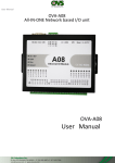
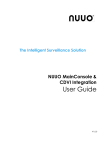
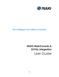
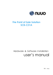
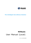
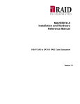
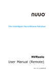
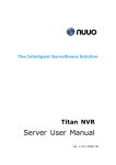
Trusted Video Management SCB-A08 User Manual Ver. 1.0.131218.00 Trusted Video Management NUUO Surveillance System - Accessory TABLE OF CONTENTS TABLE OF CONTENTS ............................................................................................................................. 1 1. INTRODUCTION .............................................................................................................................. 2 1.1.Key Features ......................................................................................................................................................... 3 1.2. OS Requirement .................................................................................................................................................. 4 1.3. System Requirement .......................................................................................................................................... 4 1.4. Specification ........................................................................................................................................................ 4 1.5. Packing List........................................................................................................................................................... 4 2. OVERVIEW .......................................................................................................................................... 5 2.1. LED Definition ....................................................................................................................................................... 7 2.2. Pin Definition ........................................................................................................................................................ 8 2.3. Digital I/O Hardware Connection ................................................................................................................... 9 2.3.1 Digital Input ................................................................................................................................................... 9 2.3.2 Digital Output ............................................................................................................................................. 10 3. NETWORK DEPLOYMENT DIAGRAM ............................................................................................ 11 4. HARDWARE SETUP ........................................................................................................................... 11 4.1. Connect SCB-A08 to Server PC ..................................................................................................................... 11 4.2. Updating an Existing Installation .................................................................................................................... 12 5. USING SEARCH TOOL .................................................................................................................. 13 5.1. Searching LAN for SCB-A08 ............................................................................................................................ 13 5.2. Configuration SCB-A08 .................................................................................................................................... 13 5.3. Server Properties................................................................................................................................................ 14 5.3.1 Default Value .............................................................................................................................................. 17 5.4. Web Server Interface ....................................................................................................................................... 18 5.5. Upgrading Firmware ........................................................................................................................................ 19 5.6. Configuration .................................................................................................................................................... 20 -1- Trusted Video Management NUUO Surveillance System - Accessory 1. Introduction SCB-A08 is an I/O box to intermediate the communication between a surveillance server and multiple peripherals. It joins up all the major components in your surveillance network to deliver your prospective management and protection over your property. This manual combs the hardware/software setup for SCB-A08. Software-wise A08 needs the server relies on NUUO surveillance system, to bring all the peripherals under control. Easy-to-mount and flexible in communication, SCB-A08 will be the pivot in your surveillance network. Thank you for choosing SCB-A08. -2- Trusted Video Management NUUO Surveillance System - Accessory 1.1.Key Features - 8 inputs (dry contact or wet contact) and 8 relay outputs provided. Supports 10/100 Mbps Ethernet. Status LED for each channels. DIN rail (optional). Supports LAN and WAN communications. In server mode supports individual 8 client sessions (socket). Management access password protected. Supports socket connection, TCP server, TCP client and UDP. Heart beat connection ensures reliable TCP connection against power failure or network disruption. Hardware watchdog (1.34 sec) -3- Trusted Video Management NUUO Surveillance System - Accessory 1.2. OS Requirement 32 bits MS Windows XP / Vista / Win 7 64 bits Win 7 / Win 8 / Win Server 2008 R2 / Win Server 2012 1.3. System Requirement The new SCB-A08 IO box can be installed in Mainconsole v5.0, NVRmini 2 v2.0, NVRsolo v2.0 and Crystal Titan 2.1 or above. 1.4. Specification Model SCB-A08 Input 8 Input Signal Dry Contact or Wet Contact (-30~-3, 3-30VDC) Relay Output 8 DC In 12+_10% V Power Consumption 1A Baud Rate Serial port1:9600, Serial port2:115200 Data Bits 5, 6, 7 or 8 Stop Bits 1, 1.5 or 2 Parity none, even, odd, mark, space Operating Temperature 0 to 70 °C (32 to 158 °F) Operation Humidity 0 – 90% (Non-Condensing) Dimension (W x H x D) 114mm*143mm*28mm (4.5 in*5.6in*1.1in) Weight 300g Certifications CE, FCC 1.5. Packing List 1. 2. 3. 4. NUUO I/O Box SCB-A08 x1 Adapter: US Power Adapter DC 12V x1 (EU with EU plug adapter) Warranty card x1 NUUO SCB-A08 CD-ROM x1 (including NUUO search tool, NUUO user manual and NUUO troubleshooting) Note: The warranty will only be honored when equipment use original factory shipped power adapters. NUUO will not be responsible for 3rd party power adaptors and any issues they might cause. -4- Trusted Video Management NUUO Surveillance System - Accessory 2. Overview To apply SCB-A08 to your surveillance system, get to know it first. Take a look around SCB-A08. The illustration below depicts SCB-A08 by top view and side view, with all major components and dimensions called out. Fig. 1. Overview Fig. 2.Side View Model SCB-A08 1 Power connection 2 Hardware reset button 3 Dip Switch 4 Ethernet port 5 Pin Terminal block 6 Serial port DTE – BD-9 male Dip Switch Mode SW1 SW2 Data (default) OFF OFF Console ON ON -5- Trusted Video Management NUUO Surveillance System - Accessory Fig. 3. Pin Terminal block Pin RS232 1 RS422 RS485 RXD(+) 2 RXD RXD(-) 3 TXD TXD(+) D(+) TXD(-) D(-) GND GND 4 5 GND Fig. 4. Serial port DTE – BD-9 male Pin RS232 RS422 1 DCD RXD(-) 2 RXD RXD(+) 3 TXD TXD(+) D(+) 4 DTR TXD(-) D(-) 5 GND GND GND 6 DSR CTS(-) 7 RTS CTS(+) 8 CTS RTS(+) 9 RI RTS(-) -6- RS485 Trusted Video Management NUUO Surveillance System - Accessory 2.1. LED Definition Name Description Link Green – 100 BaseTX Ethernet connection established Yellow – 10 BaseT Ethernet connection established Run Flashing Green – system is ready Serial 1 Green – connection established Flashing Green – data is transmitting DI/DO Green – connection established Flashing Green – data is transmitting DI1~DI8 Green – Status ON DO1~DO8 Green – Status ON -7- Trusted Video Management NUUO Surveillance System - Accessory 2.2. Pin Definition Name Description RS232/422/485 RS232/422/485 interface support RX- Receive - RX+ Receive + TX- Transmit - TX+ Transmit + GND Ground 10/100M 10/100 Mbps Ethernet SW Dip Switch Reset Hardware reset button 7~30VDC 7~30 VDC support Power DI1 Digital input Channel 1 DI2 Digital input Channel 2 DI3 Digital input Channel 3 DI4 Digital input Channel 4 DI5 Digital input Channel 5 DI6 Digital input Channel 6 DI7 Digital input Channel 7 DI8 Digital input Channel 8 GND Ground Power DO1 Digital output channel 1 CO1 Common, usually is ground DO2 Digital output channel 2 CO2 Common, usually is ground DO3 Digital output channel 3 CO3 Common, usually is ground DO4 Digital output channel 4 CO4 Common, usually is ground GND Ground Power DO5 Digital output channel 5 CO5 Common, usually is ground DO6 Digital output channel 6 CO6 Common, usually is ground DO7 Digital output channel 7 CO7 Common, usually is ground DO8 Digital output channel 8 CO8 Common, usually is ground -8- Trusted Video Management NUUO Surveillance System - Accessory GND Ground 2.3. Digital I/O Hardware Connection SCB-A08 bottom has eight switches to set Dry Contact and Wet Contact 2.3.1 Digital Input A. Digital Input Dry contact B. Digital Input Wet contact -9- Trusted Video Management NUUO Surveillance System - Accessory 2.3.2 Digital Output When Relay turn on, DO and CO will be a circuit A. AC source B. DC source - 10 - Trusted Video Management NUUO Surveillance System - Accessory 3. Network Deployment Diagram This diagram shows how server and all in one I/O box A08 are deployed within the surveillance network to work. Fig. 3. Network Deployment Diagram 4. Hardware Setup This chapter combs through the necessary setup for the major components in the surveillance network including: 1. 2. I/O box SCB-A08, Windows-based server PC. 4.1. Connect SCB-A08 to Server PC Step 1: Connect SCB-A08 to PC with Ethernet cable and apply power. Step 2: On PC, install SCB-A08 search tool. - Insert NUUO SCB-A08 CD in CD-ROM will automatically launch the Install Shield Wizard. If the Wizard does not run automatically, please enter Computer and click the CD/DVD ROM. - SCB-A08 search tool is downloadable at www.nuuo.com > Download Once search tool is successfully installed, PC auto-detects SCB-A08. - 11 - Trusted Video Management NUUO Surveillance System - Accessory Step 3: Select Next when the SCB-A08 Setup window appears. Step 4: In the Choose Destination Location window select Next to install the search tool in the default location. Select Browse to install into a user selected directory. The installation progress will be shown into complete. Step 5: Select Finish when the Install Shield Wizard Complete screen appears. When the installation is complete the Install window closes allowing the user to access the search tool in the program files. Step 6: Connect the SCB-A08 to the LAN and the run LED will flash indicating power has been applied and communications with the unit can begin. And the Link LED indicates an Ethernet connection has been made. 4.2. Updating an Existing Installation If an older version of the search tool is already installed, the Modify, repair or remove the program window will appear when the installation process is initiated: The recommended procedure is to remove all installed components first. Once the software has been removed, install the new software. - 12 - Trusted Video Management NUUO Surveillance System - Accessory 5. Using Search Tool This chapter introduces several functions of search tool: - Searching for SCB-A08 connected to the network - Displaying and changing the configuration of SCB-A08 - Upgrading the SCB-A08 firmware - Monitoring port status - Saving and loading configuration files Once the SCB-A08 is connected to LAN, the search tool will be able to search LAN for all connected SCB-A08 and will display them in a window by name and IP address. 5.1.Searching LAN for SCB-A08 Step 1: Select search tool SCB Manager in the program file menu. As soon as the search tool SCB Manager opens it will initiate Searching SCB-A08 and after a few seconds the Serial SCB-A08 List will display all SCB-A08 on the network. Step 2: To manually initiate a search for SCB-A08, on the menu side bar select Searching Server button. The Search Setup box will appear. It provides two options for searching for SCB-A08 on the network: - Specify the IP address of the SCB-A08 Search all reachable SCB-A08 Enter the IP Address assigned to the desired SCB-A08 or click Search all reachable SCB-A08, then OK. The Searching window is shown until all active SCB-A08 on the LAN are listed in the Serial Server List window. Note: Port 4001 for I/O box. 5.2. Configuration SCB-A08 Highlight the serial server in the Serial Server List window and double click to open the Server Properties window. The Server Properties window is used to configure and store the SCB-A08 configuration settings. After configuring as needed, click Update to store the configuration in the server and click Yes to restart the SCB-A08 to make sure all settings are changed to conform to the desired application. - 13 - Trusted Video Management NUUO Surveillance System - Accessory 5.3. Server Properties Step 1: Double click SCB-A08 list on SCB Manager search tool and open server properties. - Server name: The server name is user configurable. It is recommended users with more than one SCB-A08 connected to the LAN assign a new name to each. When the Manager software searches for SCB-A08 on the LAN it will display the server name allowing the user to distinguish between SCB-A08s. - Serial number: each SCB-A08 has a unique serial number. This is fixed and cannot be changed. - Password: Entering a password activates a security feature on SCB-A08. Once a password is entered it will be required to access the menu and make changes. - DHCP: DHCP servers are a part of numerous LAN management systems. The DHCP field has two selections, “Enable” or “Disable”. Arrow to the desired selection and select enter. When enabled, SCB-A08 will send a DHCP request to the DHCP server, which will assign a dynamic IP address, netmask, and gateway to the SCB-A08. If a DHCP server is not available on the network the SCB-A08 will time out after 10 seconds and the default values will remain. When DHCP is enabled, the IP address, Netmask and Gateway fields become inaccessible and cannot be changed by the user. - IP address: SCB-A08 default IP address is 192.168.2.1. A static IP address can also be assigned in this section of the menu. A dynamic address assigned by the DHCP server may change if the SCB-A08 loses the Ethernet connection or power is removed. The host (client) communication software requests a connection to the specific IP address of the serial server. If the DHCP reassigns a different IP address the software will not be able to communicate with the hardware. It is recommended to use a static IP address. A static IP address is permanent and will not change unless changed in the menu. In most cases the network administrator establishes the static address to be use. - Netmask: The default LAN netmask is configured for a Class C address. This may reconfigured by the user. - MAC address: The MAC address is not adjustable. This is assigned in the factory. Every Ethernet device manufactured has its own unique MAC address. - Version & Date: The currently loaded version of the firmware, and when it was released, are shown here. - Link status: Link status automatically displays the type of Ethernet connection. It will either display 10 BaseT or 100BaseTX in full duplex or half duplex. This will depend on the LAN, switches, hubs used in the LAN topology. - Serial port: This field indicates the number of the port for with serial server properties are currently being displayed. Changing the number in this field will cause all the other fields to display the properties for the - 14 - Trusted Video Management NUUO Surveillance System - Accessory specified port. Before changing ports, any change to properties must be Updated (Saved) or SCB-A08 will not retain them. Suggest use default setting. - Baud rate: The serial port baud rate on SCB-A08 must match the serial baud rate of the connected device. (Suggest use default setting) - Data/Parity/Stop: This setting will have to match the data format of the connected device. (Suggest use default setting) - Flow control: The flow control setting must match the connected serial device. (Suggest use default setting) - Protocol: Select TCP or UDP protocol. If the application does not require a UDP connection, select TCP. TCP guarantees reliable communication with error checking whereas UDP provides faster transmission. When UDP mode is chosen the Serial timeout, TCP alive timeout, Connection mode, Connection at, Maximum connection and Remote IP address fields are replaced with the following three fields: Destination IP address range, Port number and Source IP address range. In this mode the server can be configured to broadcast data to and receive data from multiple IP addresses. Four IP address range fields are provided. (Suggest use default setting) - Serial timeout: Default is 0, or no timeout. Setting timeout to any value between 1 and 65535 seconds activates it. If communications are idle for specified timeout value the serial server will reset and make itself available for another connection. (Suggest use default setting) - TCP alive timeout: This monitors TCP activity. If TCP activity stops for the length of time specified in this field the connection will be closed. This field can be set to any value between 0 and 255 minutes. If zero, or no value, is entered into this field the server will not disconnect. (Suggest use default setting) - Connection mode: The Connection mode field has three options, Server, Client and Client (no heartbeat). When Client or Client (no heartbeat) is selected, the Connection at field automatically becomes active (allowing the user to select Power up or Data arrival). (Suggest use default setting) When using the Virtual COM Port feature, select Server. When using a TCP or UDP Socket program, select Server. When using Paired Mode communication between two serial servers set up one as a Client and the other as a Server. When connecting to a server that does not support Heartbeat, select Client (no heartbeat). - UID: UID (Unit Identifier) is MODBUS slave address (0x0~0xff), It’s be defined in MODBUS TCP frame format, In Properties, We provide consumer define UID. (Suggest use default setting) - Delimiter HEX1 and delimiter HEX2: These two fields allow the user to enter two ASCII characters (in hex format) that delimit the beginning and end of a message. When a message with both these delimiters is received at the serial port, the data contained in the serial buffer is placed in an Ethernet packet and sent out the Ethernet port. If only Delimiter 1 is set (Delimiter 2 is zero or blank), upon receiving Delimiter 1 the SCB-A08 will put all the data in the serial buffer in an Ethernet packet and send it out the Ethernet port. If serial data greater than 1 kilobyte is received it will automatically be placed in an Ethernet packet and sent out the Ethernet port. (Suggest use default setting) - Force Transmit: This field allows the user to set a maximum time limit between transmissions of data. The value set in this field multiplied by 100 ms determines the Force Transmit time. When the elapsed time reaches the time configured in this field, the TCP/IP protocol will pack the data currently in the serial buffer into a packet and send it out the Ethernet port. (Suggest use default setting) - Port status: This field indicates whether a serial port is connected to a server or by a client. TCP/UDP port: The TCP/UDP Port defines a communication port number. In all modes of operating, Virtual COM, Direct IP, and Paired modes, both the TCP/UDP Client and server port settings must match. For I/O box configuration port is 4001. - Serial port mode: This allows configuration of the serial server for the following modes of operation: - 15 - Trusted Video Management NUUO Surveillance System - Accessory Console – When this mode is selected and the server is updated, a PC running a communication program such as Hyperterminal can communicate with the serial server via the Console Mode serial port (Port 1 on SCB-A08), displaying the Server Properties screen and allowing configuration of the server and its ports. (under 4000 port) Upgrade – When this mode is selected and the server is updated, firmware can be uploaded into the serial server via the Console Mode serial port or a virtual COM port mapped to the number of the Console Mode serial port. (under 4000 port) Default – When this mode is selected and the server is updated, it will revert the server to its default configuration. (under 4000 port) RS-232 – When this mode is selected and the server is updated, the selected serial port will become a RS-232 serial port on the server. RS-422 – When this mode is selected and the server is updated, the selected serial port will become a RS-422 serial port on the server. RS-485 – When this mode is selected and the server is updated, the selected serial port will become a RS-485 serial port on the server. - Connection at: When the Connection Mode field is set to Client or Client (no heartbeat), this field becomes active, allowing the SCB-A08 (acting as a client) to connect to the server either on Power up or on Data Arrival (first character arriving). - Maximum connection: When the Connection Mode field is set to Client or Client (no heartbeat), this field becomes active, allowing the SCB-A08 (acting as a client) to connect to the server either on Power up or on Data Arrival (first character arriving). (Suggest use default setting) - Remote IP address: This is a security feature that is activated when the IP address of the desired client is programmed into the remote IP Address setting of the menu. This tells the SCB-A08 to communicate with only the listed IP address and to filter out all other requests for connection. The SCB-A08 is setup in the menu as a TCP or UDP server to us this feature. The default setting is 255.255.255.255. It is recommended not to change this setting until the application has been tested and is communicating properly. At that point the address filtering feature of the SCB-A08 can be activated. (Suggest use default setting) Step 2: Updated server properties separately for each serial port. - 16 - Trusted Video Management NUUO Surveillance System - Accessory 5.3.1 Default Value Model SCB-A08 Server Name SCB-A08 Password -- DHCP Disable IP Address 192.168.2.1 Netmesk 255.255.255.0 Gateway 192.168.1.254 MAC Address Fixed – see bottom label Baud Rate Serial port1: 9600, Serial port2: 115200 Data/Stop bits 8-1 Parity None Flow Control None Protocol TCP Serial Timeout 0 seconds TCP Alive Timeout 0 minutes Connection Mode Server Delimiter HEX 1 00 Delimiter HEX 2 00 Force Transmit 0 ms TCP/UDP port Port 1: 4000, Port 2: 4001(I/O box) Serial Port Mode RS232 Maximum Connection 1 Remote IP Address 255.255.255.255 - 17 - Trusted Video Management NUUO Surveillance System - Accessory 5.4. Web Server Interface The Web Server interface provides the same updating options as Console Mode and Telnet. These are located at the bottom of all three Web Server pages. If a field is changed, you must click Save before leaving that page or the changes will be ignored. - 18 - Trusted Video Management NUUO Surveillance System - Accessory 5.5. Upgrading Firmware New firmware may be available at times on www.nuuo.com > Download and may downloaded and flashed to SCB-A08 currently in use. The user can upgrade using a direct connection to SCB-A08 serial port. Step 1: Download the new upgrade .hex file from www.nuuo.com > Download and place in a folder. Step 2: Ensure that the DIP switches are all in the OFF position. Step 3: Connect a null modem cable between the PC and SCB-A08. Step 4: Open the SCB Manager search tool and select the Firmware Upgrade button. Step 5: In the Serial Port selection options select the COM port number used to connect the PC to SCB-A08. Step 6: Select Browse, find the location of the firmware, select Open, and then select the upgrade button. Step 7: Software will change upgrade mode and baud rate setting automatically, then start upgrade Step 8: A window showing the Upgrade progress will appear followed by a window indicating the Upgrade was successful. Step 9: SCB-A08 will reset itself to complete the upgrade process. - 19 - Trusted Video Management NUUO Surveillance System - Accessory 5.6. Configuration Here we take NUUO surveillance system—Mainconsole for example: Step 1: Open Mainconsole on PC. Step 2: From Mainconsole tool bar, click button. Step 3: A menu opens. Step 4: Click Setting > System Setting. Step 5: Setting page opens featuring a series of tabs. Step 6: Click I/O Device tab. I/O Device tabbed page opens. - 20 - Trusted Video Management NUUO Surveillance System - Accessory Step 7: In Module field, dub SCB-A08 with a name. Step 8: By Device, specify SCB-A08 model name. Step 9: By Port, enter 4001 for I/O. Step 10: By ID, select the ID address for SCB-A08. Note: First device selects Addr:01 and so on. Step 11: Run test. If the window detect IO box successfully pop up, the setup is successfully made. Step 12: Click OK and quit setting. - 21 -