1
Using Your Universal Room Controller
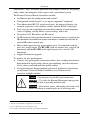
Table 3: RC-8IR and RC-6IR Rear Panel Features
#
12
13
14
15
16
5
Feature
N.U Switch
PROGRAM Switch
Function
Not used
Switch to OFF for normal operation;
Switch to ON for firmware upgrade
RS-485 TERM. Switch
Switch to ON for RS-485 line termination
FACTORY DEFAULT Button Press to return to the factory default settings, including all the configured
buttons and the network settings1
Ethernet Port
Connects to a PC or other controller through computer networking
Using Your Universal Room Controller2
This user manual is applicable once the unit is installed and configured3. The
installation process is not detailed in this user manual4, and includes:
Setting up the labels on the buttons, according to your specific
requirements5
Hardware installation
Connecting the inputs and the display
Configuration via the Windows®-based configuration software and/or
the IR learner
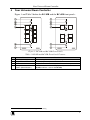
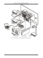
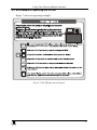
The universal room controller is very easy to use, as the example in Figure 4
and Table 4 defines6:
1 Including the factory default IP number: 192.168.1.39 (an IP number is a device'
s numerical address as expressed in the
format specified in the Internet Protocol)
2 From this section on, all the information is relevant to the RC-6IR and RC-8IR units, unless noted otherwise
3 By authorized Kramer technical personnel or by an external system integrator
4 Refer to the separate online “RC Configuration and Installation Guide” at http://www.kramerelectronics.com
5 It is recommended to place labels on the buttons prior to installing the unit, as this involves removing the face plate
6 Your RC-8IR was installed and configured to suit your specific requirements. This example describes how to setup one of
an unlimited number of available setups for the system
5