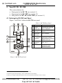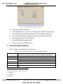
1
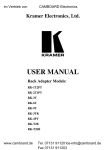
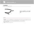
im Vertrieb von
CAMBOARD Electronics
Kramer Electronics, Ltd.
USER MANUAL
Models:
RC-7B, Media / Room Controller
RC-7BE, Media / Room Controller
www.camboard.de
Tel. 07131 [email protected]
Fax 07131 911203
im Vertrieb von
CAMBOARD
Electronics
Contents
Contents
1
2
3
4
4.1
4.2
4.3
5
5.1
5.2
5.3
6
6.1
6.2
6.3
7
Introduction
Getting Started
Overview
Your RC-7B / RC-7BE
Defining the RC-7B Front Panel
Defining the RC-7BE Front Panel
Defining the RC-7B / RC-7BE Side Panel
Using Your Media / Room Controller
Operating the RC-7B / RC-7BE
Using the Macro Buttons
An Example of Operating the RC-7B / RC-7BE
Flash Memory Upgrade
Downloading from the Internet
Connecting the PC to the RS-232 Port
Upgrading Firmware
Technical Specifications
1
2
2
4
4
5
6
8
11
12
12
13
13
13
13
14
Figures
Figure 1: RC-7B Front Panel
Figure 2: RC-7BE Front Panel
Figure 3: Side Panel of the RC-7B and RC-7BE (Enlarged View)
Figure 4: Side Panel of the RC-7B and RC-7BE
Figure 5: RC-7BE (Front Perspective) Configuration
Figure 6: RC-7BE (Rear Perspective) Configuration
Figure 7: Example of a Typical Setup in the Lecture Auditorium
Figure 8: RC-7B / RC-7BE Operation Example
Figure 9: The KFR-Programmer Window
4
5
6
7
8
9
10
12
14
Tables
Table 1: RC-7B Front Panel
Table 2: RC-7BE Front Panel
Table 3: The Commands Configuration Example
Table 4: Technical Specifications of the RC-7B / RC-7BE
www.camboard.de
4
5
11
14
i
Tel. 07131 [email protected]
Fax 07131 911203
im Vertrieb von
1
CAMBOARD
Electronics
Introduction
Introduction
Welcome to Kramer Electronics! Since 1981, Kramer Electronics has been
providing a world of unique, creative, and affordable solutions to the vast
range of problems that confront the video, audio, presentation, and
broadcasting professional on a daily basis. In recent years, we have redesigned
and upgraded most of our line, making the best even better! Our 1,000-plus
different models now appear in 11 groups1 that are clearly defined by function.
Congratulations on purchasing your Kramer RC-7B / RC-7BE media / room
controller, which is designed to let an instructor enter a multimedia
classroom and operate an A/V system with ease.
The package includes the following items:
RC-7B or RC-7BE
This user manual2
Power supply
Control and configuration software
Kramer sticker labels
This user manual is written for the end user and is applicable once the unit is
3
4
installed and configured . Refer to the separate online RC Configuration and
Installation guide for details of how to install and configure the Universal Room
5
(Media / Room) Controller .
1 GROUP 1: Distribution Amplifiers; GROUP 2: Switchers and Matrix Switchers; GROUP 3: Control Systems; GROUP 4:
Format/Standards Converters; GROUP 5: Range Extenders and Repeaters; GROUP 6: Specialty AV Products; GROUP 7:
Scan Converters and Scalers; GROUP 8: Cables and Connectors; GROUP 9: Room Connectivity; GROUP 10: Accessories
and Rack Adapters; GROUP 11: Sierra Products
2 Download up-to-date Kramer user manuals from the Internet at this URL: http://www.kramerelectronics.com
3 Including the hardware installation, connecting the inputs and the display, and configuration via the Windows®-based
software and/or the IR learner
4 By authorized Kramer technical personnel or by an external system integrator (refer to the separate online guide)
5 That provides information about how to set up the system. This online guide may well be updated on a regular basis. For
the latest online guide, go to http://www.kramerelectronics.com
www.camboard.de
1
Tel. 07131 [email protected]
Fax 07131 911203
im Vertrieb von
2
CAMBOARD
Electronics
Getting Started
Getting Started
We recommend that you:
Review the contents of this user manual
Use Kramer high performance high resolution cables1
2
A special CONFIG cable is required to configure and perform firmware
upgrades to the machine
3
Overview
The RC-7B / RC-7BE is a highly versatile controller interface panel for the
control of A/V equipment in any multimedia room, especially the control of
a projector or other display device, via RS-232 and/or IR emitter cable. The
RC-7B / RC-7BE is 12V DC fed. The RC-7B is a one-gang wall plate. The
RC-7BE is two-gang wall plate intended for the European market.
In particular, the RC-7B / RC-7BE features:
Four configurable backlit control buttons and three signal source
buttons, each of which can be programmed3 to carry out up to 15
commands, in sequence, with one press of a button
A 3.5mm CONFIG jack connector on the front panel for RS-232
configuration and control
An IR learner on the front panel for the customized control of external
sources, absorbing the IR commands from different remote transmitters
In addition, the RC-7B / RC-7BE includes:
Two IR ports
Two RS-232 serial ports for universal display
An RS-485 serial port
Control via the front panel buttons, and remotely, via RS-232
1 The complete list of Kramer cables is on our Web site at http://www.kramerelectronics.com
2 C-A35M/D9F-6
3 To be configured by the system integrator only
2
www.camboard.de
KRAMER: SIMPLE CREATIVE TECHNOLOGY
Tel. 07131 911201
[email protected]
Fax 07131 911203
im Vertrieb von
CAMBOARD
Electronics
Overview
To achieve the best performance:
Connect only good quality connection cables, thus avoiding
interference, deterioration in signal quality due to poor matching, and
elevated noise- levels (often associated with low quality cables)
Avoid interference from neighboring electrical appliances and position
the RC-7B / RC-7BE away from moisture, excessive sunlight and dust
Caution – No operator-serviceable parts inside unit.
Warning – Use only the Kramer Electronics input power
wall adapter that is provided with this unit1.
Warning – Disconnect power and unplug unit from wall
before installing or removing device or servicing unit.
1 For example: model number AD2512C, part number 2535-000251
www.camboard.de
3
Tel. 07131 [email protected]
Fax 07131 911203
im Vertrieb von
4
CAMBOARD
Electronics
Your RC-7B / RC-7BE
Your RC-7B / RC-7BE
This section defines the:
Front panel of the RC-7B (see section 4.1)
Front panel of the RC-7BE (see section 4.2)
Side panel of the RC-7B and RC-7BE (see section 4.3)
4.1 Defining the RC-7B Front Panel
Figure 1 and Table 1 define the RC-7B front panel:
Table 1: RC-7B Front Panel
#
1
2
3
4
Feature
Configurable
Control
Buttons (4)
Mounting
holes (2)
Function
Macro Buttons for
controlling the room and
the A/V equipment
For fastening the controller
in place
Faceplate
Attachment
Holes (2)
CONFIG Port2
on 3.5mm jack
connector
For attaching the faceplate
to the controller1
5
SIGNAL
SOURCES
Buttons
6
IR IN Receiver
Used for Windows®-based
configuration software
(driver downloads, firmware
updates and so on)
Select the input source
(from 1 to 3)
Accepts IR remote
commands (for the
IR-learner feature)3
Figure 1: RC-7B Front Panel
1 These screws should not be removed during or after mounting
2 Via the front panel, without having to remove the RC-7B from its mounting
3 Letting you configure the RC-7B directly from the remote transmitter without the need for software
4
www.camboard.de
KRAMER: SIMPLE CREATIVE TECHNOLOGY
Tel. 07131 911201
[email protected]
Fax 07131 911203
im Vertrieb von
CAMBOARD
Electronics
Your RC-7B / RC-7BE
4.2 Defining the RC-7BE Front Panel
Figure 2 and Table 2 define the RC-7BE front panel:
Figure 2: RC-7BE Front Panel
Table 2: RC-7BE Front Panel
#
1
Feature
Mounting holes (4)
Function
For fastening the controller in place
2
Faceplate Attachment Holes (2)
For attaching the faceplate to the controller1
3
Configurable Control Buttons (4)
4
CONFIG Port2 on 3.5mm jack
connector
Macro Buttons for controlling the room and the
A/V equipment
Used for Windows®-based configuration
software (driver downloads, firmware updates
and so on)
5
SIGNAL SOURCES Buttons
Select the input source (from 1 to 3)
6
IR IN Receiver
Accepts IR remote commands (for the IRlearner feature)3
1 These screws should not be removed during or after mounting
2 Via the front panel, without having to remove the RC-7BE from its mounting
3 Letting you configure the RC-7BE directly from the remote transmitter without the need for software
www.camboard.de
5
Tel. 07131 [email protected]
Fax 07131 911203
im Vertrieb von
CAMBOARD
Electronics
Your RC-7B / RC-7BE
4.3 Defining the RC-7B / RC-7BE Side Panel
Figure 3 illustrates an enlarged view of the side panel of the RC-7B and
RC-7BE:
Figure 3: Side Panel of the RC-7B and RC-7BE (Enlarged View)
Figure 4 defines the side panel of the RC-7B and RC-7BE. For an
explanation of how to install and configure, refer to the chapter entitled:
Installation of the RC System in the online RC Configuration and
Installation guide1.
1 Download it from http://www.kramerelectronics.com
6
www.camboard.de
KRAMER: SIMPLE CREATIVE TECHNOLOGY
Tel. 07131 911201
[email protected]
Fax 07131 911203
im Vertrieb von
&
CAMBOARD
Electronics
Your RC-7B / RC-7BE
/
.
)
% .
0 )%
).%
%
1
,! &' 234,!56& %
.
(
%
'* !+
',,)
- '()
)
%.
&
'( )
7
4
!"#
$%
7
/
$%
8 #3 7
(
*(3
9
#3
% 01
.
0
Figure 4: Side Panel of the RC-7B and RC-7BE
www.camboard.de
7
Tel. 07131 [email protected]
Fax 07131 911203
im Vertrieb von
5
CAMBOARD Electronics
Using Your Media / Room Controller
Using Your Media / Room Controller1
The example in Figure 5 shows a front view perspective of a typical
RC-7BE configuration. It connects to the projector via IR or RS-232:
Figure 5: RC-7BE (Front Perspective) Configuration
1 From this section on, all the information is relevant to both the RC-7B and the RC-7BE, unless noted otherwise
8
www.camboard.de
KRAMER: SIMPLE CREATIVE TECHNOLOGY
Tel. 07131 911201
[email protected]
Fax 07131 911203
im Vertrieb von
CAMBOARD Electronics
Using Your Media / Room Controller
The example in Figure 6 shows a rear view perspective of a typical RC-7BE
configuration. It connects to the projector via RS-232. The connected
sources—the DVD and VCR—connect to the dedicated video and audio
inputs of the projector:
Figure 6: RC-7BE (Rear Perspective) Configuration
www.camboard.de
9
Tel. 07131 [email protected]
Fax 07131 911203
im Vertrieb von
CAMBOARD Electronics
Using Your Media / Room Controller
Figure 7 shows the RC-7BE built into a podium in an auditorium with an
overhead projector and a cabinet with a VCR and a DVD inside, all
controlled via the RC-7BE. The presenter’s laptop is located on the podium,
next to the RC-7BE. It is also controlled by the RC-7BE and is used for
presentations and slide shows.
VCR
DVD
Figure 7: Example of a Typical Setup in the Lecture Auditorium
10
www.camboard.de
KRAMER: SIMPLE CREATIVE TECHNOLOGY
Tel. 07131 911201
[email protected]
Fax 07131 911203
im Vertrieb von
CAMBOARD Electronics
Using Your Media / Room Controller
5.1 Operating the RC-7B / RC-7BE
In the example defined in Table 3, the RC-7B buttons are labeled ON, OFF,
VOL UP, VOL DOWN on the control buttons and PC, DVD and VCR on
the Signal Source buttons and programmed by the system integrator to
perform one or more tasks1.
Table 3: The Commands Configuration Example
ON Button Macro Sequence
1. Power up the projector
4. Brief delay for the projector to heat up
2. Power up the DVD
5. The projector selects the PC input
3. Power up the VCR
OFF Button Macro Sequence
1. Power down the projector
4. Stop the VCR
2. Stop the DVD
5. Power down the VCR
3. Power down the DVD
VOL UP Button Macro Sequence
1. Increase the volume level
VOL DOWN Button Macro Sequence
1. Decrease the volume level
VCR Button Macro Sequence
1. Stop the DVD
3. Play the VCR
2. The projector selects the VCR input
DVD Button Macro Sequence
1. Stop the VCR
3. Play the DVD
2. The projector selects the DVD input
PC Button Macro Sequence
1. Stop the DVD
3. The projector selects the PC input
2. Stop the VCR
1 A macro sequence, including up to 15 commands per button, carried out in sequence with one press of a button
www.camboard.de
11
Tel. 07131 [email protected]
Fax 07131 911203
im Vertrieb von
CAMBOARD Electronics
Using Your Media / Room Controller
5.2 Using the Macro Buttons
Pressing any button initiates a macro sequence1, during which the button
blinks (as programmed by the system integrator).
If during the macro sequence the button blinks faster than usual2, this indicates
that a malfunction has been detected3 and the RC-7B / RC-7BE exits the macro
sequence.
To solve the problem, summon technical help
If you want to stop a macro sequence, press and hold that button for 5
seconds. The sequence will come to an end. You can resume operation by
pressing any of the buttons4. The unit will carry out the macro sequence
commands from the beginning.
5.3 An Example of Operating the RC-7B / RC-7BE
Figure 8 shows an example of how to operate the RC-7B / RC-7BE:
ON
DVD
PC
VCR
Select the DVD input on the projector and play the DVD.
Select the PC input on the projector and resume the slide show.
Select the VCR input on the projector and show the video film.
PC
Select the PC input on the projector and show the last few slides of the
presentation.
OFF
Power down the projector, DVD player and the video player.
Figure 8: RC-7B / RC-7BE Operation Example
1 The macro sequence can be carried out instantly or can take a while, depending on the delay times included in the sequence
2 Six times per second, as compared with twice per second during normal operation
3 For example, when pressing ON to power up the projector while the projector is still in the power down process
4 Including the button you kept pressed to stop the macro sequence
12
www.camboard.de
KRAMER: SIMPLE CREATIVE TECHNOLOGY
Tel. 07131 911201
[email protected]
Fax 07131 911203
im Vertrieb von
6
CAMBOARD
Electronics
Flash Memory Upgrade
Flash Memory Upgrade
The RC-7B1 device firmware is located in FLASH memory, which lets you
upgrade to the latest Kramer firmware version in minutes!
The process involves:
Downloading the upgrade package from the Internet
Connecting the PC to the RS-232 port
Upgrading the firmware
6.1
Downloading from the Internet
You can download the up-to-date file2 from the Internet. To do so:
1. Go to our Web site at http://www.kramerelectronics.com and download the
file: “SetKFRXXX-xx.zip” from the technical support section.
2. Extract the file “SetKFRXXX-xx.zip” package, which includes the
KFR-Programmer application setup, the .s19 firmware file and the Web
Applet dat file, to a folder (for example, C:\Program Files\KFR Upgrade).
3. Install the KFR-Programmer Application.
6.2
Connecting the PC to the RS-232 Port
Before installing the latest Kramer Ethernet firmware version on the RC- B,
do the following:
1. Connect the special CONFIG cable3 to the CONFIG port on the RC-7B
device and then connect the special CONFIG cable via Null-modem adapter
and a 9-wire flat cable to the RS-232 9-pin D-sub COM port on your PC.
2. Set the PROGRAM switch to ON.
3. Connect the power on your machine.
6.3
Upgrading Firmware
Follow these steps to upgrade the firmware:
1. Double-click the KFR-Programmer desktop icon.
The KFR-Programmer window appears.
1 This procedure applies also to the RC-7BE
2 File names are liable to change from time to time
3 C-A35M/D9F-6
www.camboard.de
13
Tel. 07131 [email protected]
Fax 07131 911203
im Vertrieb von
CAMBOARD
Electronics
Technical Specifications
Figure 9: The KFR-Programmer Window
2. Select the required COM Port1.
3. Click the File button to select the .s19 firmware file included in the package.
4. Click the Send button to download the file. The Send button lights red.
5. Wait until downloading is completed and the red Send button turns off.
6. Disconnect the power on the RC device.
7. Set the PROGRAM switch to OFF.
8. Connect the power on the RC device.
7
Technical Specifications
Table 4 defines the technical specifications:
2
Table 4: Technical Specifications of the RC-7B / RC-7BE
PORTS:
OUTPUTS:
POWER SOURCE:
DIMENSIONS:
WEIGHT:
ACCESSORIES:
OPTIONS:
2 bi-directional RS-232 on terminal block connectors; 1 RS-485 on a terminal
block connector; Config. jack connector for RS-232 configuration and control
2 IR emitters on terminal block connectors
12 VDC, 155mA
RC-7B:
7.1cm x 4.4cm x 13.7cm (2.8" x 1.75" x 5.39", W, D, H)
RC-7BE:
15.1cm x 4.4cm x 8.6cm (5.94" x 1.75" x 3.39", W, D, H)
0.3kg (0.67lbs.) approx
Power supply, Windows®-based Kramer control and configuration software
3
4
Dual IR emitter cable , single IR emitter cable , IR extension cable, CONFIG.
5
cable
1 To which the RC device is connected on your PC
2 Specifications are subject to change without notice
3 C-A35M/2IRE
4 C-A35M/IRE
5 C-A35M/D9F-6
14
www.camboard.de
KRAMER: SIMPLE CREATIVE TECHNOLOGY
Tel. 07131 911201
[email protected]
Fax 07131 911203
im Vertrieb von
CAMBOARD Electronics
LIMITED WARRANTY
Kramer Electronics (hereafter Kramer) warrants this product free from defects in material and workmanship under the
following terms.
HOW LONG IS THE WARRANTY
Labor and parts are warranted for seven years from the date of the first customer purchase.
WHO IS PROTECTED?
Only the first purchase customer may enforce this warranty.
WHAT IS COVERED AND WHAT IS NOT COVERED
Except as below, this warranty covers all defects in material or workmanship in this product. The following are not covered
by the warranty:
1. Any product which is not distributed by Kramer, or which is not purchased from an authorized Kramer dealer. If you are
uncertain as to whether a dealer is authorized, please contact Kramer at one of the agents listed in the Web site
www.kramerelectronics.com.
2. Any product, on which the serial number has been defaced, modified or removed, or on which the WARRANTY VOID
IF TAMPERED sticker has been torn, reattached, removed or otherwise interfered with.
3. Damage, deterioration or malfunction resulting from:
i) Accident, misuse, abuse, neglect, fire, water, lightning or other acts of nature
ii) Product modification, or failure to follow instructions supplied with the product
iii) Repair or attempted repair by anyone not authorized by Kramer
iv) Any shipment of the product (claims must be presented to the carrier)
v) Removal or installation of the product
vi) Any other cause, which does not relate to a product defect
vii) Cartons, equipment enclosures, cables or accessories used in conjunction with the product
WHAT WE WILL PAY FOR AND WHAT WE WILL NOT PAY FOR
We will pay labor and material expenses for covered items. We will not pay for the following:
1. Removal or installations charges.
2. Costs of initial technical adjustments (set-up), including adjustment of user controls or programming. These costs are the
responsibility of the Kramer dealer from whom the product was purchased.
3. Shipping charges.
HOW YOU CAN GET WARRANTY SERVICE
1. To obtain service on you product, you must take or ship it prepaid to any authorized Kramer service center.
2. Whenever warranty service is required, the original dated invoice (or a copy) must be presented as proof of warranty
coverage, and should be included in any shipment of the product. Please also include in any mailing a contact name,
company, address, and a description of the problem(s).
3. For the name of the nearest Kramer authorized service center, consult your authorized dealer.
LIMITATION OF IMPLIED WARRANTIES
All implied warranties, including warranties of merchantability and fitness for a particular purpose, are limited in duration to
the length of this warranty.
EXCLUSION OF DAMAGES
The liability of Kramer for any effective products is limited to the repair or replacement of the product at our option. Kramer shall
not be liable for:
1. Damage to other property caused by defects in this product, damages based upon inconvenience, loss of use of the product, loss
of time, commercial loss; or:
2. Any other damages, whether incidental, consequential or otherwise. Some countries may not allow limitations on how long an
implied warranty lasts and/or do not allow the exclusion or limitation of incidental or consequential damages, so the above
limitations and exclusions may not apply to you.
This warranty gives you specific legal rights, and you may also have other rights, which vary from place to place.
NOTE: All products returned to Kramer for service must have prior approval. This may be obtained from your dealer.
This equipment has been tested to determine compliance with the requirements of:
EN-50081:
EN-50082:
CFR-47:
"Electromagnetic compatibility (EMC);
generic emission standard.
Part 1: Residential, commercial and light industry"
"Electromagnetic compatibility (EMC) generic immunity standard.
Part 1: Residential, commercial and light industry environment".
FCC* Rules and Regulations:
Part 15: “ Radio frequency devices
Subpart B Unintentional radiators”
CAUTION!
Servicing the machines can only be done by an authorized Kramer technician. Any user who makes changes or
modifications to the unit without the expressed approval of the manufacturer will void user authority to operate the
equipment.
Use the supplied DC power supply to feed power to the machine.
Please use recommended interconnection cables to connect the machine to other components.
* FCC and CE approved using STP cable (for twisted pair products)
www.camboard.de
15
Tel. 07131 [email protected]
Fax 07131 911203
im Vertrieb von
CAMBOARD Electronics
For the latest information on our products and a list of Kramer
distributors, visit our Web site: www.kramerelectronics.com,
where updates to this user manual may be found.
We welcome your questions, comments and feedback.
Safety Warning:
Disconnect the unit from the power supply before
opening/servicing.
Caution
Kramer Electronics, Ltd.
Web site: www.kramerelectronics.com
www.camboard.de
E-mail: [email protected]
P/N:07131
2900- 2 911201
4 REV 3 [email protected]
Tel.
Fax 07131 911203