1
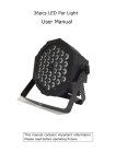
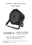
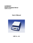
25*6W LED Matrix Strobe User Manual This manual contains important information. Please read before operating fixture. 1 SECURITY TIPS WARNING!!! To reduce the risk of fire, electric shock, or injury to persons, follow these important safety instructions: non-professionals, not to disassemble the light arbitrarily and lighting accessories inside. rated voltage range: AC110V-120V/60Hz or AC200V-240V / 50HZ (to be selected). not beam irradiate the flammable materials, flammable materials and the lamp should be maintained at least 1M over the distance. lamps used in ambient temperature: -15 ℃ -40 ℃, the highest temperature of the surface of the lamp: 60 ℃. to keep away from the liquid substance and humid environment. before using the lights must ensure the good grounding, can not install charging and remove any parts. the installation of lamps, must be fixed screw fasteners with additional security cable and regular inspection. lamps consecutive working hours is not recommended more than 10 hours. should stop using the lights in time when happens unusual conditions during the process lamp parts of the rotation, external accessories and paste parts should be regular inspected, such as the emergence of loose and rock, should be reinforced in a timely manner to prevent the accident. lamps adopt strong winds to refrigerate, it is easy to accumulate the dust, so you have to clean it weekly especially the cooling air opening, otherwise the dust will plug leading to poor light 1 2 TECHNOLOGY REFERENCE Voltage: AC 100-240V 50/60Hz Power consumption: 250W max. Separate strobe, strobe Rate: 0 to 30 Hz Color: White bright LEDs Mode of control: DMX 512 protocol, master/slave, auto, sound active with adjustable sound sensitivity Channel: 4/25/30 DMX channel modes Displaying off 5 seconds automatically after finishing sets of the fixture Beam Angle (strobe): 25° Field Angle (strobe): 45° Coverage Angle (colony): 80° Environmental temperature: -20℃ to 40℃ Hanging brackets included Net weight: 4.0Kgs Dimensions:367*391*102mm(L*W*D) 3 Board Instruction Take one item and set the item at auto, or sound active as above,then get other items and press the button MODE, set at SLON,confirm by the button of ENTER, then connect the items at SLON to the item at AUTO or SOUND ACTIVE, disconnect the items from DMX controller, the items will work simultaneously. The item at auto or sound active works as master, others as slave. LED DISPLAY CONTROL: Main menu Sub menu 1.A001 001-512(ADDRESS SETTING) 2.CH29 4/25/30CH(CHANNEL MODES) 3.SH01 ON/OFF(PRESET SHOWS) 4.SP 01-10(PRESET SHOWS RUNNING SPEED) 2 5.SnoF ON/OFF(SOUND ACTIVE) 6.Sn01 01-10(SOUND ACTIVE SENSITIVITY ADJUSTING) 7.o255 000-255(DIMMER) 8.St01 01-10(STROBE SPEED) 9.SLoF ON/OFF(SLAVE) 10.rdoF ON/OFF(DISPLAYING REVERSEDLY) Replacing the fuse If the fine-wire fuse of the device fuses, only replace the fuse by a fuse of same type and rating. Before replacing the fuse, unplug mains lead. Procedure: Step 1: Open the fuse holder on the rear panel with a fitting screwdriver. Step 2: Remove the old fuse from the fuse holder. Step 3: Install the new fuse in the fuse holder. Step 4: Replace the fuse holder in the housing. 4 DMX CHANNEL SHEET 4-CHANNEL MODE Channel 1 white from 0% to 100% Channel 2 strobe from slow to fast Channel 3 preset shows 0-64 not occupied 65-191 11 preset shows 92-255 14 sound active modes Channel 4 running speed 0-2 running speed adjustments from slow to fast when ch3 55 at 65-191 0-2 sound sensitivity adjustments from small to big when 55 ch3 at 192-255 25-CHANNEL MODE Channel 1 LED output 1 3 Channel 2 LED output 2 Channel 3 LED output 3 Channel 4 LED output 4 Channel 5 LED output 5 *** Channel 21 LED output 21 Channel 22 LED output 22 Channel 23 LED output 23 Channel 24 LED output 24 Channel 25 LED output 25 30-CHANNEL MODE Channel white from 0% to 100% 1 Channel strobe from slow to fast 2 Channel color fade 3 Channel preset shows 4 0-64 not occupied 65-191 11 preset shows 192-255 14 sound active modes Channel 5 running speed 0-255 running speed adjustments from slow to fast when ch3 at 65-191 0-255 sound sensitivity adjustments from small to big when ch3 at 192-255 Channel LED output 1 6 Channel LED output 2 7 Channel LED output 3 8 4 Channel LED output 4 9 Channel LED output 5 10 *** Channel LED output 21 26 Channel LED output 22 27 Channel LED output 23 28 Channel LED output 24 29 Channel LED output 25 30 5 FIXED EQUIPMENT Please fasten the fixture clamp before hanging. The clamp can be fasten by the little hole in the middle of the bracket, then tie with a safety belt. The loading capacity of the safety belt should be 10 times than the weight of the fixture itself. 6 CONNECTION OF DMX-512 AND CONNETION WITH THE LIGHT EQUIPMENT Please connect XLR-XLR control wire with every light from the output of DMX. XLR connection : 5 ATTENTION: Please do remember to connect one circle circuit plug on the output signal of last equipment. And this circle circuit plug was connected a 120ohm resistance between terminals 2 and 3 of the CANON plug, connect this circle circuit plug can avoid the signal flash phenomena of signal DMX512 during the transmission. 7 Maintenance Problems Check list Trouble Shooting The fixture do not work 1. If your power as same as the input of the machine. 1. Make sure the voltage. LED dimmed 2. If the fuse was broken. If your power us same as the input of the machine No DMX input 1. If the polarity is opposited in the DMX controller. 2. If it is in DMX mode. 3. If there are 2 Master in a loop. 2. Replace the same fuse. Make sure the voltage input. 1. Correct the DMX polarity. 2. Change to the DMX mode. 3. Set one piece into 6 Par Light Set works abnormality 1. Check if the serial is correct on the Par Light display Slave mode. 1. Set the right serial No on the single Par Light 8 AFTER SERVICE 1. Our company offer technical consultation to customers for ever. 2. If the machine is wrong and need repairmen, please truthfully fill in the related content and feedback us the problems timely, as well as we have to improve the product. 3. In addition to the lamp, also matching accessories are as follows: accessories:Power line 1 piece Optional parts:(customers) Warranty Card Name Model Production End User Sale Store Company Name: Link man: Tel: Purchase Stamp Add: Description: These must be truthfully fill, seal by the end-user and point-of-sale, or else the warranty will not work (warranty period and terms, see the following) warranty period:one year since purchase warranty terms:1、If fail when using the product in normal state, you can made under the provisions of the warranty, show the warranty card and purchase bills(copy), and enjoy free maintenance service in a specific service center or the manufacturer. 7 2. The following will be the implementation of paid service: (1)Without the effective warranty card (2)There’s blank, alter and no point-of-sale name (3)Fail caused by unresistance (4)Fail caused by transportation or unloading (5)Fail caused by not operate by manual (6)Fail caused by disassemble without unauthorized (7)Fail caused by using the unauthorized control system Note: Based on our company continue to improve the product, the statement containing data may have changed, and will not notice the change any more. Company retains its right to change specifications related when product is improved. Thanks for your understanding. 8