1
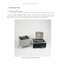
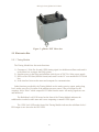
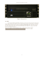
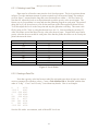
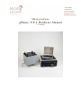
Micro-g LaCoste
gPhone / P.E.T Hardware Manual
V1 manual
Microg LaCoste gPhone/P.E.T Meter
TABLE OF CONTENTS
1.
INTRODUCTION ...............................................................................................................................................2
1.1
2.
GPHONE / PET
SYSTEM..................................................................................................................................2
THE GPHONE / PET SYSTEM OVERVIEW.................................................................................................3
2.1
THE METER BOX ............................................................................................................................................3
2.2
ELECTRONICS BOX .........................................................................................................................................4
2.2.1
Timing Module.......................................................................................................................................4
2.2.1.1
2.3
3.
Timing Module Rear Connections...................................................................................................................... 5
UPS................................................................................................................................................................6
METER SETUP...................................................................................................................................................7
3.1
SITE SELECTION .............................................................................................................................................7
3.2
SETUP THE SYSTEM ........................................................................................................................................7
3.3
CONNECTING THE SYSTEM .............................................................................................................................7
3.4
SOFTWARE SETUP FOR A NEW SITE ................................................................................................................8
3.4.1
Setting latitude, longitude and elevation ...............................................................................................8
3.4.2
Run Ocean Load ....................................................................................................................................8
4.
RUN THE METER .............................................................................................................................................8
4.1
4.2
4.3
4.4
4.5
4.6
POWER THE GPHONE / PET.............................................................................................................................8
START COMMUNICATION ................................................................................................................................9
LEVEL THE METER .........................................................................................................................................9
CLAMPING / UNCLAMPING ............................................................................................................................10
RANGING THE METER ...................................................................................................................................10
RECORDING DATA ........................................................................................................................................10
5.
NETWORKING THE METER .......................................................................................................................11
6.
LEVEL CHECK ................................................................................................................................................12
6.1
LEVEL CHECK INTRODUCTION......................................................................................................................12
6.2
LEVEL CHECK PROGRAM INSTALL ...............................................................................................................12
6.3
LEVEL CHECK TEST ......................................................................................................................................12
6.3.1
Collecting Level Data ..........................................................................................................................13
6.3.2
Creating a Data File............................................................................................................................13
6.3.3
Run the Level Check Program.............................................................................................................14
6.3.4
View the Results...................................................................................................................................14
7.
HISTORY OF THE LACOSTE AND ROMBERG EARTH TIDE METER..............................................15
8.
SYSTEM SPECIFICATIONS..........................................................................................................................15
8.1
8.2
8.3
PERFORMANCE .............................................................................................................................................15
POWER..........................................................................................................................................................15
WEIGHT AND DIMENSIONS ...........................................................................................................................15
1
Microg LaCoste gPhone/P.E.T Meter
1. INTRODUCTION
1.1 gPhone / PET System
The gPhone / PET system is compact in size and light weight compared to earlier earth
tide meters. Figure 1- gPhone / PET shows the complete system. The system has three major
parts: the Meter box with DAQ - data acquisition system (grey box), the Electronics box which
holds the UPS and Timing Module (black box), and a laptop PC running gMonitor.
Figure 1- gPhone / PET Hardware
2
Microg LaCoste gPhone/P.E.T Meter
2. THE gPhone / PET SYSTEM OVERVIEW
The Meter box (
Figure 2 - gPhone / PET Meter box) houses the sensor and the
data acquisition circuitry; the Electronics box (Figure 6- Electronics box) consists of the GPS
and Rubidium clock Timing Module, a UPS, power supplies, and output connectors; the laptop
gets gravity and GPS data and runs the control software which is called gMonitor. These 3 parts
are connected by a number of cables.
2.1 The Meter Box
The gravity sensor of the gPhone / PET system consists of a low drift, metal, Zero Length
Spring system and a CPI (Capacitance Position Indicator) electrostatic feedback system. A fine
screw allows the user to adjust spring tension to ensure a world-wide gravity range. The linear
electronic feedback system has a range of between 50 to 100 milliGal (+/- 25 to +/-50 milliGal)
depending on the meter, which should enable the system to operate for more than two years
without having to re-range the range screw and spring system.
The gPhone / PET sensor is installed inside a well insulated double-oven to insure very
accurate and stable temperature control so that the sensor is not affected by the changes of
ambient temperature. The inner oven is filled with dry air to provide a stable humidity
environment for the sensor. Isolation from changes of ambient (outside) humidity and pressure
changes are provided by 3 sealed chambers: The inner oven chamber that houses the sensor is
thick walled aluminum and is O-ring sealed and leak tested. The outer oven is thick walled
aluminum and is O-ring sealed and pressure tight as well. The outer grey box is also O-ring
sealed, which provides water tightness and additional sealing. All electrical connectors and
hardware connections between these boxes and to the outside environment are air tight.
The DAQ system circuitry is housed in the meter box. The sensitive electronic feedback
and data acquisition boards are inside the outer oven for temperature stability. In addition to the
physical precautions made for a stable system, the gPhone / PET system also monitors and
records the temperatures and pressures of both the sensor and the ambient environment. This
data can be used to provide software corrections to the gravity data. The two pressures and two
temperatures are digitized with sufficient accuracy for their intended use. The gravity and level
signals are digitized with very accurate 24 bit A/D converters and very stable voltage references.
The digital signals are then sent serially thru the large grey cable to the multi-serial card in the
Timing Module in the Electronics case.
3
Microg LaCoste gPhone/P.E.T Meter
Figure 2 - gPhone / PET Meter box
2.2 Electronics Box
2.2.1 Timing Module
The Timing Module has four main functions:
1) Generates a 1 Pulse Per Second (1PPS) timing signal via rubidium oscillator and sends it
to the Meter box to trigger the DAQ system.
2) Supplies power to the meter and rubidium clock by an AC/DC 24v 100w power supply.
3) Receives the GPS data (NEMA format) and sends it to the PC over another RS-232 serial
line.
4) Is the interface between the meter and computer for communication
Other functions provided by the Timing Module are the analog gravity output, analog long
level, analog cross level, location of the ambient pressure sensor, extra serial input for the
computer, and a “Echo” which outputs RS-232 data from the meter. All analog signals are raw
and unfiltered.
The Rubidium Lock LED located on the front of the Timing Module indicates the
rubidium has reached a stable state and is now outputting a constant 1 PPS signal.
The 1 PPS Lock LED on the front of the Timing Module indicates the rubidium clocks 1
PPS output is now slaved to the GPS 1PPS.
4
Microg LaCoste gPhone/P.E.T Meter
2.2.1.1 Timing Module Rear Connections
Connections on the back of the timing module are (from the left to right):
1.
2.
3.
4.
5.
6.
7.
8.
9.
GPS - Threaded connector type TNC for external GPS antenna. Use if possible.
Main – Meter data/power cable (grey) Lemo locking connector. Required.
1 PPS – One pulse per second from GPS/Rubidium to Meter box. BNC. Required.
10 MHz sine wave – From Rubidium clock. Testing purposes only. BNC.
10 MHz TTL wave - From Rubidium clock. Testing purposes only. BNC.
Analog Cross level –Raw analog cross level signal (unfiltered). BNC.
Analog Long level – Raw analog long level signal (unfiltered). BNC.
Analog gravity – Raw analog gravity signal (unfiltered). BNC.
Computer - 4 Port Serial. Low flat rectangular connectors to Laptop PCMCIA card.
Required.
10. Echo – RS232 Serial data from Meter box. Buffered. Male DB9 connector. Use a straight
through cable with F/F gender changer to read on PC.
11. Aux com – Extra serial input to PC. Male DB9 connector.
12. AC Power – 85/240 50/60 Hz main power input. Fused with 250V 3AG fuse.
Figure 3 - Timing Module rear connections
Figure 4 - Timing Module Left rear
Figure 5 - Timing Module right rear
5
Microg LaCoste gPhone/P.E.T Meter
Figure 6- Electronics box
2.3 UPS
A rack mount Uninterruptible Power Supply is used to protect the electronics from power
surges and provides power for the system in case of short term power interruptions. The UPS is
mounted at the bottom of the electronic box (Figure 6- Electronics box). The following links
give more details on the UPS. You must choose at order time which AC voltage (110 or 220
VAC) your UPS will operate at.
http://www.tripplite.com/shared/pdf/spec/tlspec_2658.pdf (for 120 VAC input)
http://www.tripplite.com/shared/pdf/spec/tlspec_2687.pdf (for 220 VAC input)
6
Microg LaCoste gPhone/P.E.T Meter
3. METER SETUP
3.1 Site Selection
To ensure high quality data, always select a site that is isolated from environmental noise
(seismic, wind, etc.) and extreme temperature changes. An isolated concrete pier inside a quiet
laboratory would be a good site. Setting the gPhone / PET meter on the ground underneath a tree
in a city would be a very bad choice. Also trying to run the meter in any tall building is not
recommended, even in the basement. Urban or city environments tend to be noisy seismically.
3.2 Setup the System
• Set the meter box on the designated site -hopefully on a concrete slab or pier.
• (optional) Place the 3 round footpads provided underneath the leveling feet to help
reduce high frequency vibrations. The slotted pad goes underneath the adjustable cross
level leg. The pad with the hole goes under the fixed cross level leg. Lastly the flat pad
goes underneath the adjustable long level leg. Note: If you want the meter to be more
sensitive to vibrations do not use the footpads.
• Set the electronic box (power and timing module) nearby but not on the concrete pier
where the meter box is set up.
• Set the laptop computer on top of the electronic box
3.3 Connecting the System
• Plug the UPS input power cable to an AC power source (either 120 VAC or 220 VAC,
depending which UPS you ordered), but do not turn the UPS power on yet. WARNING UPS CAN ONLY BE USED ON VOLTAGE SPECIFIED AT ORDER TIME. IT IS
NOT UNIVERSAL INPUT.
• Plug in the AC power cable from the Timing Module to the output of the UPS system
• Plug in the laptop AC power cable to a 110 or 220 AC outlet.
• Connect the Main grey data/power cable (metal Lemo connectors on either end) to the
connectors labeled “Main” on the Timing Module and Meter Box. (
Figure 2 gPhone / PET Meter box) Make sure the red dots are matching between the male and
female connectors so that they connect smoothly. Do not force the connectors. (This
cable bundled with Coax 1 PPS cable)
• Connect the black coax cable with BNC connectors on both ends to the connectors on the
Timing Module and Meter Box labeled 1 PPS. (This cable is bundled with the Main
cable)
• If available connect the GPS antenna to the connector labeled GPS on the Timing
Module. It is recommended that the meter is connected to a GPS.
• Connect the short black cable with flat rectangular connectors (4 port serial cable) from
the connector labeled “Computer” on the timing module to the laptop computer’s
PCMCIA serial card.
• Turn on the UPS power
• Turn on the Timing module
• Turn on the computer
7
Microg LaCoste gPhone/P.E.T Meter
3.4 Software Setup for a New Site
Now that the meter is in a new location it is necessary to set the correct latitude,
longitude, elevation, and ocean load.
3.4.1 Setting Latitude, Longitude and Elevation
•
•
•
•
•
•
Start the gMonitor software.
Go to System ⎜ Settings ⎢ Setup ⎢ Position
Enter in the new latitude, longitude and elevation.
Select OK.
Go to File ⎢ Save.
Prompt “Overwrite programs main .INI file?” select OK.
3.4.2 Run Ocean Load
• Go to System ⎢ Settings ⎢ Corrections
• In the “Tidal Model” box select which tide model is to be applied. Refer to the gMonitor
Software Manual for a description of the options. Then click the Setup button.
• Click the Run Ocean Load button. Refer to the gMonitor Software Manual for information
on all the files.
• Select OK.
• Go to File ⎢ Save.
• Prompt “Overwrite programs main .INI file?” select OK.
4. RUN THE METER
4.1 Power the gPhone / PET
When the gPhone / PET is on power, the heater system is at work to bring the sensor to
the preset “nose” temperature. This nose temperature is set at the factory to minimize changes in
gravity caused by small changes in temperature. Generally, the following rules apply for the
systems power up period.
• If the meter is off power for 1 minute or less then it will usually recover in less than 10
minutes.
• If the meter is off power for 30 minutes or less, it needs at least 12 hours to stabilize.
• If the meter is powered off 2 hours or more, it needs at least 48 hours to stabilize.
• It is good practice to power up the meter immediately after receiving it and to keep it on
power at all times (unless you are shipping it).
• It is normal to observe higher drift rate during the first several days after the meter has
been transported, re-ranged, and/or off power.
• Leveling and ranging the meter should be done after the meter has reached steady state.
8
Microg LaCoste gPhone/P.E.T Meter
Rapid and inconsistent drift rates will occur during the meters warm up period. It may
take up to a week for a normal drift rates to be achieved after the meter has been off heat. It is
common to see lower drift rates the longer it is on heat.
4.2 Start Communication
• To start communication between the meter and computer a new file must created in
gMonitor.
• Go to File ⎢ New and create a new directory for the data files that will be created.
• Once a directory has been selected communication will begin. At this point though, the
system is NOT storing data! It will give the user a chance to level and range the meter
before data is stored.
4.3 Level the Meter
• Communication between the meter and the computer must be active for the level positions
to update. To establish communication see the “Start Communication” section.
• Adjust the cross level position close to zero by twisting the adjustable cross level leg (See
Figure 7). If the error is negative turn the leg counterclockwise. If the error is positive
turn the leg clockwise. If the number does not change keep adjusting in the appropriate
direction.
• Adjust the long level position close to zero by twisting the adjustable long level leg (See
Figure 7). The direction of the adjustment is the same as the cross level leg.
• It may be necessary to go back and fine tune the cross then the long.
Figure 7 – Level Legs
The meters levels should be checked and re adjusted a few hours after leveling.
Temperature and settling footpads will cause the levels to change in the first few hours.
9
Microg LaCoste gPhone/P.E.T Meter
4.4 Clamping / Unclamping
• Communication between the meter and the computer must be active to clamp and unclamp
the meter. To establish communication see the “Start Communication” section.
• To Clamp the meter go to System ⎢ Clamp or use the shortcut keys Alt + C
• To Unclamp the meter go to System ⎢ Unclamp or use the shortcut keys Alt + U. When
the meter is unclamping an audible vibration noise will come from the meter. This is to
help assist the meter to unsettle from its clamped position.
• If you are following the setup procedure step by step now is the time to unclamp the meter.
4.5 Ranging the Meter
The meter may need to be re-ranged when brought to a new location because of the
gravity difference between the old location and the new location is greater than the feedback
range. Use Auto-Range to automatically re-range the meter to be within the feedback range.
Use the Increase or Decrease for fine tuning the range closer to zero or your preferred starting
gravity value. Auto-Range could take up to 30 minutes so be patient.
• Communication between the meter and the computer must be active to re-range the meter.
To establish communication see the “Start Communication” section
• To range the meter go to System ⎜ Set Range
• To automatically range the meter within the feedback range, click Auto-Range. When the
meter is auto-ranging an audible vibration noise will come from the meter. As with
unclamping it is to help the meter unsettle from its resting position so the electronic
feedback can gain control of the beam.
• Once the meter is within range, use the Increase or Decrease buttons to get to your desired
starting gravity value.
The gauge located in the Set Range window indicates the position of the beam. When the
meter is within range and is being held by the feedback system the red needle will be in the
center. Refer to the gMonitor software manual for more information on ranging.
4.6 Recording Data
Before recording starts the meter should meet the following conditions:
•
•
•
•
•
•
•
The meter is at an appropriate gravity site.
All necessary connections have been made
The meter is at a stable temperature meaning it has been on for at least 48 hours.
The software is correctly set up for your location.
Communication between the meter and computer is active.
The long and cross levels are close to zero.
The meter is unclamped, in range, and reading gravity.
10
Microg LaCoste gPhone/P.E.T Meter
With these conditions met, start recording data by going to System ⎜ Process ⎜ Start or
use the shortcut key F5. Refer to the gMonitor software manual for more information on
recording data.
5. NETWORKING THE METER
Many users have requested that their gPhone / PET meters be available over the Internet.
We have installed Virtual Network Connection (VNC) software on the gPhone / PET meter
laptop PC. There is also a copy of this software on the installation CD. This software enables
you to see a virtual real-time image of the LCD screen on the gPhone / PET meter PC over any
fast internet connection. You can interact with gPhone / PET computer/meter just as if you were
at the actual keyboard of the gPhone / PET meter! Dial up modems are not recommended; they
can work but will have very poor screen quality and very slow speed of update.
To install the VNC viewer software on the remote PC:
Go to the VNC directory on the install CD. Double click on “vnc-3.3.7-x86_win32.exe”
to start installation. When you get to the “Select Components” setup screen, unselect “VNC
Server”. The remote PC only has to act as a viewer. The gPhone / PET meter PC is set up as a
server. The software is quite small. Important: You need to turn off any MS or 3rd party
firewalls on both computers.
To access a gPhone / PET meter you need to know the IP address and password for that
meter’s VNC connection. At the factory, a default password of “MGL” is set up. So you just
need to know the IP address (xx.xx.xx.xx) of the gPhone / PET computer you need to remotely
access. This can be easily determined by moving the PC’s cursor over the VNC server icon in
the QuickStart Taskbar. Start up the VNC server software on the meter’s PC, then start up the
RealVNC viewer, type in the IP address xxx.xxx.xxx.xxx in the first window, then in the next
window type the password. The remote computer will then show a full size window of the
gPhone / PET meter’s PC.
You can change the viewer window size and scaling by changing settings in the
“Options” click box on the Connections window (where you enter IP address). Be careful not to
get confused about which PC you are working on. You can look at data or transfer files from the
gPhone / PET meter to the remote PC. You can also clamp/unclamp, re-range, or change settings
or anything that you could do at the meter PC itself. Just be careful – updating the screen on the
remote PC can take many seconds depending on Internet speed and commands can stack up for
many seconds before executing.
If you need to re-install the server software on the meter’s computer the same steps are
followed as above, but leave the VNC Server box checked. You can specify a new password this
way also. Also to run the VNC server software you need to turn off any firewalls (or set them so
that the VNC software can get through them)
11
Microg LaCoste gPhone/P.E.T Meter
6. LEVEL CHECK
6.1 Level Check Introduction
After the shipment, it is always a good practice to check the instrument levels and see if
the level setting has been changed during the shipment and reset the level if necessary. The
correct level positions are where the meter is vertical in both the X and Y (Long and Cross)
directions. This occurs when the gravity output is a maximum. Once this point is found an
electronic offset can be applied to the levels so that they read zero when the actual sensor is
level. This test is done by tilting the meter and recording the levels and gravity at different
positions. The equation that shows the relation between gravity and the instrument level is
shown below:
g obs = g max − g 0 (1 − cos(α (l − l 0 )) cos( β ( x − x0 )))
where g obs is the observed gravity reading; g max is the maximum gravity reading; g 0 is the
nominal gravity value at the site (980,000,000 µGal); α and β are the coefficients of the level in
the long and cross directions respectively. l and l 0 are the levels and set points in the long
direction; x and x 0 are the levels and set points in the cross direction.
6.2 Level Check Program Install
The levelChk.exe program takes in the level and gravity data from the level check test
and computes the level parameters. The three files necessary to run levelChk are:
• levelChk.exe
• levelChk.ctf
• MCRInstaller.exe.
INSTALL the program:
1. Copy levelChk.exe and levelChk.ctf from the MGL CD to your working
directory.
2. Run the MCRInstaller.exe program from the CD
3. Run the levelChk.exe program. This may take 10-30 seconds to actually get
started.
6.3 Level Check Test
Before you start doing the level check, make sure that the meter is stable, i.e. it has been
on power for the required period of time and has been re-ranged so the feedback is in range and
is not drifting too much. It is important that this test be done in a quiet as location as possible.
12
Microg LaCoste gPhone/P.E.T Meter
6.3.1 Collecting Level Data
Data must be collected to enter into the level check program. The level positions shown
in figure 7 are the minimum amount of points required to get an accurate fitting. The numbers
given in figure 7 assume that the long and cross maximums are within +/- 500 level units. To
start the test, adjust the levels to each position and record the gravity value at each point. The
fastest way to get good data is to stop and start the gMonitor program at each point. The point of
doing this is so you do not have to wait for the transients of the filter applied to Mean Gravity.
To do this adjust the levels to the first point and stop the gMonitor recording. Then start a new
file by going to File ⎜ New or using the shortcut keys Alt + N. Start recording by pressing F5.
After one minute record the Mean Gravity value on a sheet of paper. Repeat these steps until a
gravity value has been recorded for each point. Note that the points do not have to be exactly the
points shown on the chart.
Long
0
-500
-500
0
500
500
500
0
-500
Cross
0
0
-500
-500
-500
0
500
500
500
Gravity
Figure 8 - Level Points
6.3.2 Creating a Data File
Now that a gravity value has been recorded for each point on a sheet of paper it is time to
create a computer file with these values. Create a Tab delimited file in Wordpad with the data
order of “Long” “Cross” and “Gravity”, but without any header. Here is an example:
0
-500
-500
0
500
500
500
0
-500
0
0
-500
-500
-500
0
500
500
500
4390
4345
4245
4348
4299
4357
4334
4383
4328
Save the file with a .txt extension, such as MeterXX Levels.txt.
13
Microg LaCoste gPhone/P.E.T Meter
6.3.3 Run the Level Check Program
• Open levelChk.exe. Note it may take 15-20 seconds for the window to pop up.
• Select the file you have just created from section 6.3.2 and select open
• The output file created will be in the same directory as levelChk.exe and will be
named LevelPar.txt
6.3.4 View the Results
Open the LevelPar.txt file. An example output file is given below. This is not the output
file for the example data in section 6.3.2.
Gravity = 351.5 uGal
Cross Coefficient = 2.152919e-007
Cross offset = -222.0
Long Coefficient = 2.677852e-007
Long offset = 172.3
The observed gravity - model:
2042 -180 223.0
-5.6
-1675 80 238.0
8.5
-226 -74 345.0
-0.4
-679 1841 226.0
-3.4
825 1739 254.0
4.8
1442 -776 290.0
2.1
-749 -620 319.0
0.9
-996 153 297.0
-3.3
-689 -817 314.0
-3.4
-886 -180 309.0
-3.1
-143 -63 347.0
-0.4
-214 158 343.0
0.0
366 161 350.0
3.2
514 146 344.0
-0.3
416 524 336.0
-0.8
680 1742 255.0
0.2
845 1021 301.0
0.5
520 357 337.0
-2.6
780 -496 347.0
10.2
961 -1076 310.0
-3.1
-1030 1253 251.0
-0.3
-854 606 295.0
-3.9
STD after correction: 3.9 uGal
The level check program computes a best fit for gravity using each level position. The
number on the far right is the error from the fit in ugals for that point. If one or more of these
errors is very large you should check to see if you entered the data correctly for those points. The
standard deviation after the level correction is written out at bottom of data. Information you
need to reset the level parameters is shown below.
Cross Coefficient = 2.152919e-007
Cross offset = -222.0
Long Coefficient = 2.677852e-007
Long offset = 172.3
14
Microg LaCoste gPhone/P.E.T Meter
The coefficients returned by the level check program are in radians/AD. The coefficients
are used to calculate the off level error for the level correction(see appendix B for the equation
that shows the relationship of off level to gravity).
To reset the level parameters, go to System ⎜ Setting ⎜ Corrections in gMonitor and
change the LongSP and CrossSP. If the newly calculated offset is negative it must be subtracted
from the current value. If the offset is positive it must be added to the current value. To change
the coefficients go to System ⎜ Settings ⎜ Calibration and look in the levels box.
7. HISTORY OF THE LACOSTE AND ROMBERG EARTH TIDE METER
The first Earth Tide Gravity meter was produced by LaCoste and Romberg in about
1952. The ET meter has a double-oven heating system for thermal stability, and a zero-backlash
gearbox that allows the meter to be nulled mechanically with minimal backlash effects. The
earliest ET meters used an optical beam position reading system that was replaced later by a CPI
(capacitance position indicator) system. CPI-based linear electrostatic feedback systems have
replaced the mechanical stepper motor nulling system. The first LaCoste & Romberg Portable
Earth Tide (PET) meters were made in the early 1990’s and had MVR electronic feedback for
nulling. The design and development of the PET meter was started in 2004 and refined in 2006.
8. SYSTEM SPECIFICATIONS
8.1 Performance
• System Resolution: 0.01 µGal
• Range: 7000 milliGal
8.2 Power
•
•
•
•
•
110 or 220 VAC input to the UPS system must be selected at purchase time
Full load maximum (charging the UPS batteries) 250W @ 27 ºC
Average load
90W @27 ºC
Fuse in Timing Module- 250V - 3 amp
How long will the UPS last if the power goes out?
Conditions:
- UPS is fully charged before blackout
- Load on the UPS is the timing box and meter only
- Ambient temperature 27ºC
- Meter temperature is at steady state at the time of the blackout
With these conditions the UPS will last approximately 4 hours
8.3
Weight and Dimensions
• Weight
o Meter box
o Electronics box
13kg
30kg
15
Microg LaCoste gPhone/P.E.T Meter
o Laptop computer
o Carrying case
o Total
•
Dimensions (WxLxH)
o Meter box
o Electronics box
o Laptop
o Carrying case
3kg
12kg
58kg
31x32.5x25.2 cm (meter leg height is 9 cm)
42.5x51x20.5cm
26.5x32.5x4 cm
48.8x51.2x48 cm
16