1
TI ARM Lab 7
Temperature Sensor
National
Science
Foundation
Funded in part, by a grant from the
National Science Foundation
DUE 1068182
Acknowledgements
Developed by Craig Kief, Brian Zufelt, and Jacy Bitsoie at the Configurable Space Microsystems
Innovations & Applications Center (COSMIAC). Co-Developers are Bassam Matar from Chandler-Gilbert
and Karl Henry from Drake State. Funded by the National Science Foundation (NSF).
Lab Summary
This lab introduces the concepts of the sampling and data passing on the ARM processor.
Lab Goal
The goal of this lab is to continue to build upon the skills learned from previous labs. This lab helps the
student to continue to gain new skills and insight on the C code syntax and how it is used in the TI
implementation of the ARM processor. Each of these labs will add upon the previous labs and it is the
intention of the authors that students will build with each lab a better understanding of the ARM processor
and basic C code, syntax and the new pieces of hardware that make up this system. Even though these labs
(or tutorials) assume the student has not entered with a knowledge of C code, it is the desire that by the time
the student completes the entire series of tutorials that they will have a sufficient knowledge of C code so as
to be able to accomplish useful projects on the ARM processor.
Learning Objectives
The student should begin to become familiar with the concept of the temperature sensor and ways to
continue to accomplish simple projects. One idea could be an entertainment center in your home. It might
have been poorly designed. As the super sharp designer, you might want to attach a fan but only have it
come on when the temperature is really hot. Your handy ARM processor could be used to do just that.
Microchip Technology Inc.’s TCN75A digital temperature sensor (like the one on the ORBIT board)
converts temperatures between -40°C and +125°C to a digital word, with ±.1°C (typical) accuracy. The
TCN75A product comes with user-programmable registers that provide flexibility for temperature-sensing
applications. The chip is the small eight pin device on the Orbit board that has an IC4 under it. Some
typical Applications include:
• Personal Computers and Servers
• Hard Disk Drives and Other PC Peripherals
• Entertainment Systems
• Office Equipment
• Data Communication Equipment
• General Purpose Temperature Monitoring
The key to remember is that I2C is nothing new. It was used in Lab 7 for the accelerometer. I2C is an
amazing bus architecture that all individuals that work with microcontrollers or microprocessors need to
have a working knowledge of. It is possible to hang hundreds of small sensors off the same pair of wires
and to address them individually only by the use of their unique address (shown in their datasheets).
This lab involves introductions to the temperature sensor and then the utilization of the UART to display the
temperature on the computer.
Grading Criteria
N/A
Time Required
Approximately one hour
Lab Preparation
It is highly recommended that the student read through this entire procedure once before actually using it as
a tutorial. It is also recommended that the tutorial software was run first to preload compiler options and
source files as well as to load many of the main.c files.
Equipment and Materials
It is assumed that the student has already completed prior labs and the software is installed properly.
Software needed
Quantity
Install the tutorial framework from the autoinstaller located at
1
http://cosmiac.org/thrust-areas/academic-programs-and-designservices/education-and-workforce-development/community-portal/ . The
designer will also want Putty or similar RS-232 terminal program for viewing
the UART output.
Hardware needed
Quantity
The hardware required is the TI Tiva LaunchPad Kit and the Digilent Orbit
board
1
Additional References
The Evaluation Board user’s manual is on this web site: http://datasheet.octopart.com/EK-TM4C123GXLTexas-Instruments-datasheet-15542121.pdf and the manuals for the Digilent orbit board are located at
http://digilentinc.com/Products/Detail.cfm?NavPath=2,396,1181&Prod=ORBIT-BOOSTER. Here is the
datasheet for the temperature sensor http://ww1.microchip.com/downloads/en/DeviceDoc/21935a.pdf .
Here is the place to find and download putty www.putty.org.
COSMIAC tutorials found at: http://cosmiac.org/thrust-areas/academic-programs-and-designservices/education-and-workforce-development/microcontrollers/ate-developed-material/
2
Lab Procedure
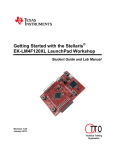
Figure 1. ARM and ORBIT Combination
This picture of the correct way to mate the Tiva LaunchPad and the Digilent Orbit boards together. Please
do so at this point and connect them as shown in Figure 1.
Figure 2. Code Composer Icon
Launch Code Composer and where prompted, chose the workspaces location to store your project (as shown
in Figure 3).
3
Figure 3. Workspace Selection
Since the installer for the workshop has been run prior to this, the user will be presented with the following
view (Figure 4) where all lab projects exist.
Figure 4. CCS Starting Point
The laboratory material is created to have the students type in a lot of the code. Only by typing the code
and then debugging the errors will a user ever really understand how to do projects. For the sake of this
activity, the source code is provided at the end of the tutorial. In Lab 8, open main.c. Then either type in
all the code from attachment 2 or copy and paste in the code from Attachement 2 into main.c. Once again, it
is easy to just copy and paste in all the code but what is learned is very minimal. The true power is typing
in the code and dealing with the errors that you will create.
4
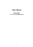
Just as with the accelerometer, the temperature sensor has an I2C interface. Remember that it is possible to
hang hundreds of items onto this bus and only deal with them individually through their unique addresses.
This is shown in Figure 5 and is very similar to the one showed in Tutorial 7. I2C has two wires: SDA and
SCL.
Figure 5. Temperature Sensor Overview
Many parts can share the I2C bus. Think of it as many grapes hanging on the grapevine. The difference is
that you must have a scheme for knowing when each of the pieces is communicated with. This is done with
addresses. Each device has a different 7 bit address which is how it is identified. In the case of this
temperature sensor, the address is shown below in Figure 6.
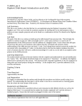
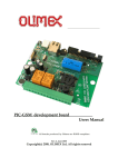
Figure 6. Temperature Sensor Datasheet Excerpt
The portion of the datasheet copied for Figure 6 shows the address for connecting the temperature sensor to
the system. The very first line of code is a define: #define TEMP_ADDR 0x4F. This is how you create the
address in the project to link the I2C pieces to the main project.
This is also a good place to introduce “global” versus “local” variables. In the code below, there are four
variables declared. The first two are character (char) strings: start_screen and log. The [29] designates them
as a character string that is 29 bytes long. The first two are done before and outside of the main function
that runs the project. These are called global variables and can be seen by any function in the project. The
second two are declared within the main function: temp_data and i. These are local variables and can only
5
be seen from within the main function. From a design perspective, always use local variables when
possible. It will reduce the debugging time later.
unsigned char start_screen[29] = "\n\n\r ATE Lab 8 Temp Sensor \n\n\r"; //29 bytes long
unsigned char log[18] = "\n\n\r Temp reading: "; //18 bytes long
//two function headers that will be defined later
void Print_header();
void Read_temp(unsigned char *data);
// Prints Header
// Read Temperature sensor
//start of main program
void main(void) {
unsigned char temp_data[10] = "00.0 C \n\n\r";
unsigned short int i = 0;
// Temp format to be edited by read
The next section sets up the I2C. There is nothing different here than was used in the last lab. This section
must be included any time there is a desire to use I2C. The informational part here is to explain where these
functions come from. By googling “tivaware device driver users guide” you will be taken to this page as an
option: http://www.ti.com/tool/sw-tm4c . Open this file: TivaWare™ Peripheral Driver Library for C
Series User's Guide. It is actually a driver library. According to this document, the Texas Instruments®
Tiva® Peripheral Driver Library is a set of drivers for accessing the peripherals found on the Tiva family of
ARM® Cortex™-M based microcontrollers. While they are not drivers in the pure operating system sense
(that is, they do not have a common interface and do not connect into a global device driver infrastructure),
they do provide a mechanism that makes it easy to use the device’s peripherals. As an example, when this
pdf is opened, if the designer searches for “SysCtlPeripheralEnable” then they will be taken to the page
shown in Figure 7.
Figure 7. Hyperlink for Drivers
The key to remember is just how powerful this ARM processor is. If you glance through this document’s
table of contents then it is clear to see just how powerful it is. There are functions for using ADC, CAN,
I2C, UART, USB, ….. For the purposes of this tutorial (and the other tutorials), the projects are being
reduced to the bare minimum.
6
Figure 8. Enabling and Configuring Ports and Pins
As shown above in Figure 8, first the peripherals are enabled. Next the General Purpose IO pins are
configured. The final line is where the I2C address is assigned through the variable “TEMP_ADDR”.
Figure 9. Enabling and Configuring the UART
The next set of code that is shown above is the UART code. This sets the normal variables that designer are
used to seeing with a UART (115200, 8, none, 1). Once again, each of these functions can be found in the
driver user guide. Take the time to compare the two sets of code above. Look at how similar the first four
lines of each section are. These four lines are mandatory for any time there is a desire to use a peripheral.
The first two lines enable the peripheral. The second two lines configure the GPIO pins.
void Print_header(){
// Print Header at start of program
int i = 0; // general counter
for(i=0;i<29;i++){ // Print Header at start of program
UARTCharPut(UART0_BASE, start_screen[i]); //Print to UART here
}
}
The next set of code shown above is nothing more than a print function. It takes the global variable called
start_screen that was declared as a global variable at the top of the program and sends it out to the UART
screen.
void Read_temp(unsigned char *data){
// Read Temperature sensor
unsigned char temp[2];
// storage for data
I2CMasterControl(I2C0_MASTER_BASE, I2C_MASTER_CMD_BURST_RECEIVE_START);
SysCtlDelay(20000);
// Delay
// Start condition
temp[0] = I2CMasterDataGet(I2C0_MASTER_BASE);
SysCtlDelay(20000);
// Delay
// Read first char
I2CMasterControl(I2C0_MASTER_BASE, I2C_MASTER_CMD_BURST_RECEIVE_CONT);
SysCtlDelay(20000);
// Delay
// Push second Char
7
temp[1] = I2CMasterDataGet(I2C0_MASTER_BASE);
I2CMasterControl(I2C0_MASTER_BASE, I2C_MASTER_CMD_BURST_RECEIVE_FINISH);
data[0] = (temp[0] / 10) + 0x30;
// convert 10 place to ASCII
data[1] = (temp[0] - ((temp[0] / 10)*10)) + 0x30;
if(temp[1] == 0x80){
data[3] = 0x35;
}
else{
data[3] = 0x30;
}
// Read second char
// Stop Condition
// Convert 1's place to ASCII
// Test for .5 accuracy
}
The final set of code is shown above. This code is designed to read temperature from the temperature
sensor and format it the right way. The BURST_RECEIVE_START and BURST_RECEIVE_FINISH are
constants that are used to identify the START and END conditions on the I2C line. For the displayed
temperature values, the plan is xx.x where the xx is a whole number, the decimal point is a fixed value and
the final x is a value that is either .5 or .0. Temp[0] is the value on the left side of the decimal point and
temp[1] is the value on the right hand side of the decimal point. The assignment of the data [0, 1, and 3] are
done next. The crazy looking code there is to convert the information from HEX to ASCII. Data 0 and 1
are the left two positions/numbers. Data 2 is the fixed decimal point and data 3 is the value on the right
hand side of the decimal point (0 or 5).
The next part is dependent on if you have the word file or the pdf in a classroom. If you are doing this as
part of the workshop, you should now look at main.c. If you are part of the workshop, you will now see
parts that need to be typed in. All of the final code is shown in Attachment 2. When all the final code is
typed in, click on the debug icon/bug as shown in Figure 10.
Figure 10. Debug Window
Figure 11. Run and Stop
Click on the green angle to load the program and then on the red square to exit debug mode. It is important
to exit the debug mode to allow Putty and the UART to work correctly by freeing up the port.
Start Putty.
8
Figure 12. Putty Configuration
Launch the Putty program with the configuration settings shown above in Figure 12. Note that your comm
port will most likely be different than this one. You will have to go to your Device Manager to ensure you
have the correct comm port for your computer.
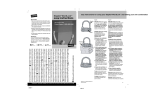
Figure 13. Temperature Output
As shown on Figure 13, once the program is running the designer can visualize the output on Putty. The
temperature is displayed. Now, by putting your finger on the IC4 chip on the Orbit board, it is possible to
raise the temperature. This same system could be used to control fans or other items in a house based on
specific temperatures. By pressing the reset button on the Tiva board it is possible to restart the program
and see the ATE Lab line.
Challenge – Change the text that is displayed, remove the decimal point, turn on LEDs at certain times.
9
Attachment 1: main.c file (starting file)
/*******************************************************
Project : Orbit Lab 7 ATE (Temp With UART)
Version : 1.0
Date : 2/20/2013
Author : Brian Zufelt / Craig Kief
Company : COSMIAC/UNM
Comments:
This lab will extend the concepts from LAB 7. This Lab
will pull data from the temperature sensor found on the
Orbit board and output the data through the UART to be
read from a terminal program.
******************************************************
Chip type
: ARM TM4C123GH6PM
Program type
: Firmware
Core Clock frequency
: 80.000000 MHz
*******************************************************/
#define TEMP_ADDR 0x4F
// Address for Temp Sensor
// Define needed for pin_map.h
#define PART_TM4C123GH6PM
#include
#include
#include
#include
#include
#include
#include
#include
#include
#include
#include
#include
#include
#include
<stdbool.h>
<stdint.h>
"inc/tm4c123gh6pm.h"
"inc/hw_memmap.h"
"inc/hw_types.h"
"driverlib/gpio.h"
"driverlib/pin_map.h"
"driverlib/sysctl.h"
"driverlib/uart.h"
"inc/hw_i2c.h"
"driverlib/i2c.h"
"inc/hw_ints.h"
"driverlib/interrupt.h"
"driverlib/timer.h"
unsigned char start_screen[29] = "\n\n\r ATE Lab 8 Temp Sensor \n\n\r";
unsigned char log[18] = "\n\n\r Temp reading: ";
void Print_header();
void Read_temp(unsigned char *data);
// Prints Header
// Read Temperature sensor
void main(void) {
unsigned char temp_data[10] = "00.0 C \n\n\r";
unsigned short int i = 0;
// Temp format to be edited by read
// general counter
// Setup the I2C see lab 7
**************************************************************************************************************************
SysCtlClockSet(SYSCTL_SYSDIV_1 | SYSCTL_USE_OSC | SYSCTL_OSC_MAIN | SYSCTL_XTAL_16MHZ); //setup clock
SysCtlPeripheralEnable(SYSCTL_PERIPH_I2C0);
SysCtlPeripheralEnable(SYSCTL_PERIPH_GPIOB);
// Enable I2C hardware
// Enable Pin hardware
GPIOPinConfigure(GPIO_PB3_I2C0SDA);
GPIOPinConfigure(GPIO_PB2_I2C0SCL);
// Configure GPIO pin for I2C Data line
// Configure GPIO Pin for I2C clock line
GPIOPinTypeI2C(GPIO_PORTB_BASE, GPIO_PIN_2 | GPIO_PIN_3); // Set Pin Type
GPIOPadConfigSet(GPIO_PORTB_BASE, GPIO_PIN_2, GPIO_STRENGTH_2MA, GPIO_PIN_TYPE_STD);
GPIOPadConfigSet(GPIO_PORTB_BASE, GPIO_PIN_3, GPIO_STRENGTH_2MA, GPIO_PIN_TYPE_OD);
DRAIN
// SDA MUST BE STD
// SCL MUST BE OPEN
I2CMasterInitExpClk(I2C0_BASE, SysCtlClockGet(), false);
// The False
sets the controller to 100kHz communication
I2CMasterSlaveAddrSet(I2C0_BASE, TEMP_ADDR, true);
// false means transmit
//*****************************************************************************************************************************************
***********
// Setup the UART see lab 6
**************************************************************************************************************************
10
SysCtlPeripheralEnable(SYSCTL_PERIPH_UART0);
SysCtlPeripheralEnable(SYSCTL_PERIPH_GPIOA);
// Enable UART hardware
// Enable Pin hardware
GPIOPinConfigure(GPIO_PA0_U0RX);
// Configure GPIO pin for UART RX line
GPIOPinConfigure(GPIO_PA1_U0TX);
// Configure GPIO Pin for UART TX line
GPIOPinTypeUART(GPIO_PORTA_BASE, GPIO_PIN_0 | GPIO_PIN_1);
// Set Pins for UART
UARTConfigSetExpClk(UART0_BASE, SysCtlClockGet(), 115200,
// Configure UART to 8N1 at 115200bps
(UART_CONFIG_WLEN_8 | UART_CONFIG_STOP_ONE | UART_CONFIG_PAR_NONE));
//*****************************************************************************************************************************************
***********
Print_header();
// Print Header
while(1){
Read_temp(temp_data);
SysCtlDelay(6000000);
// Read Data from Temp Sensor
// Delay
/*************************************************************************
* The value of the temperature sensor is placed in the array temp_data. Printout
* this string using a FOR loop.
*************************************************************************/
}
}
void Print_header(){
// Print Header at start of program
int i = 0; // general counter
for(i=0;i<29;i++){ // Print Header at start of program
UARTCharPut(UART0_BASE, start_screen[i]);
}
}
void Read_temp(unsigned char *data){
// Read Temperature sensor
unsigned char temp[2];
// storage for data
/**********************************************************************************************************
* The Temperature sensor provides 2 bytes that are the C degrees. Create code to read these bytes and place
* them in temp[0] & temp[1].
**********************************************************************************************************/
ASCII
data[0] = (temp[0] / 10) + 0x30;
// convert 10 place to ASCII
data[1] = (temp[0] - ((temp[0] / 10)*10)) + 0x30;
// Convert 1's place to
if(temp[1] == 0x80){
// Test for .5 accuracy
data[3] = 0x35;
}
else{
data[3] = 0x30;
}
}
11
Attachment 2: main.c file (solution)
/*******************************************************
Project : Orbit Lab 7 ATE (Temp With UART)
Version : 1.0
Date : 2/20/2013
Author : Brian Zufelt / Craig Kief
Company : COSMIAC/UNM
Comments:
This Lab will pull data from the temperature sensor found on the
Orbit board and output the data through the UART to be
read from a terminal program.
******************************************************
Chip type
: ARM TM4C123GH6PM
Program type
: Firmware
Core Clock frequency
: 80.000000 MHz
*******************************************************/
#define TEMP_ADDR 0x4F
// Address for Temp Sensor
// Define needed for pin_map.h
#define PART_TM4C123GH6PM
#include
#include
#include
#include
#include
#include
#include
#include
#include
#include
#include
#include
#include
#include
<stdbool.h>
<stdint.h>
"inc/tm4c123gh6pm.h"
"inc/hw_memmap.h"
"inc/hw_types.h"
"driverlib/gpio.h"
"driverlib/pin_map.h"
"driverlib/sysctl.h"
"driverlib/uart.h"
"inc/hw_i2c.h"
"driverlib/i2c.h"
"inc/hw_ints.h"
"driverlib/interrupt.h"
"driverlib/timer.h"
unsigned char start_screen[29] = "\n\n\r ATE Lab 8 Temp Sensor \n\n\r";
unsigned char log[18] = "\n\n\r Temp reading: ";
void Print_header();
void Read_temp(unsigned char *data);
// Prints Header
// Read Temperature sensor
void main(void) {
unsigned char temp_data[10] = "00.0 C \n\n\r";
unsigned short int i = 0;
// Temp format to be edited by read
// general counter
// Setup the I2C see lab 7
**************************************************************************************************************************
SysCtlClockSet(SYSCTL_SYSDIV_1 | SYSCTL_USE_OSC | SYSCTL_OSC_MAIN | SYSCTL_XTAL_16MHZ); //setup clock
SysCtlPeripheralEnable(SYSCTL_PERIPH_I2C0);
SysCtlPeripheralEnable(SYSCTL_PERIPH_GPIOB);
// Enable I2C hardware
// Enable Pin hardware
GPIOPinConfigure(GPIO_PB3_I2C0SDA);
GPIOPinConfigure(GPIO_PB2_I2C0SCL);
// Configure GPIO pin for I2C Data line
// Configure GPIO Pin for I2C clock line
GPIOPinTypeI2C(GPIO_PORTB_BASE, GPIO_PIN_2 | GPIO_PIN_3); // Set Pin Type
DRAIN
GPIOPadConfigSet(GPIO_PORTB_BASE, GPIO_PIN_2, GPIO_STRENGTH_2MA, GPIO_PIN_TYPE_STD);
GPIOPadConfigSet(GPIO_PORTB_BASE, GPIO_PIN_3, GPIO_STRENGTH_2MA, GPIO_PIN_TYPE_OD);
// SDA MUST BE STD
// SCL MUST BE OPEN
I2CMasterInitExpClk(I2C0_BASE, SysCtlClockGet(), false);
// The False
sets the controller to 100kHz communication
I2CMasterSlaveAddrSet(I2C0_BASE, TEMP_ADDR, true);
// false means transmit
//*****************************************************************************************************************************************
***********
// Setup the UART see lab 6
**************************************************************************************************************************
12
SysCtlPeripheralEnable(SYSCTL_PERIPH_UART0);
SysCtlPeripheralEnable(SYSCTL_PERIPH_GPIOA);
// Enable UART hardware
// Enable Pin hardware
GPIOPinConfigure(GPIO_PA0_U0RX);
// Configure GPIO pin for UART RX line
GPIOPinConfigure(GPIO_PA1_U0TX);
// Configure GPIO Pin for UART TX line
GPIOPinTypeUART(GPIO_PORTA_BASE, GPIO_PIN_0 | GPIO_PIN_1);
// Set Pins for UART
UARTConfigSetExpClk(UART0_BASE, SysCtlClockGet(), 115200,
// Configure UART to 8N1 at 115200bps
(UART_CONFIG_WLEN_8 | UART_CONFIG_STOP_ONE | UART_CONFIG_PAR_NONE));
//*****************************************************************************************************************************************
***********
Print_header();
// Print Header
while(1){
Read_temp(temp_data);
SysCtlDelay(6000000);
for(i=0;i<10;i++){
UARTCharPut(UART0_BASE, temp_data[i]);
}
// Read Data from Temp Sensor
// Delay
// Loop to print out data string
}
}
void Print_header(){
// Print Header at start of program
int i = 0; // general counter
}
for(i=0;i<29;i++){ // Print Header at start of program
UARTCharPut(UART0_BASE, start_screen[i]);
}
void Read_temp(unsigned char *data){
// Read Temperature sensor
unsigned char temp[2];
// storage for data
I2CMasterControl(I2C0_BASE, I2C_MASTER_CMD_BURST_RECEIVE_START);
SysCtlDelay(20000);
// Delay
temp[0] = I2CMasterDataGet(I2C0_BASE);
char
char
// Read first
SysCtlDelay(20000);
// Delay
I2CMasterControl(I2C0_BASE, I2C_MASTER_CMD_BURST_RECEIVE_CONT);
SysCtlDelay(20000);
// Delay
temp[1] = I2CMasterDataGet(I2C0_BASE);
I2CMasterControl(I2C0_BASE, I2C_MASTER_CMD_BURST_RECEIVE_FINISH);
ASCII
// Start condition
data[0] = (temp[0] / 10) + 0x30;
// convert 10 place to ASCII
data[1] = (temp[0] - ((temp[0] / 10)*10)) + 0x30;
// Push second Char
// Read second
// Stop Condition
// Convert 1's place to
if(temp[1] == 0x80){
// Test for .5 accuracy
data[3] = 0x35;
}
else{
data[3] = 0x30;
}
}
13
Attachment 3: Block Diagram of the Pins Used in Projects
14
15
Attachment 4: ASCII Table
16