1
TI ARM Lab 8
Accelerometers
National
Science
Foundation
Funded in part, by a grant from the
National Science Foundation
DUE 1068182
Acknowledgements
Developed by Craig Kief, Brian Zufelt, and Jacy Bitsoie at the Configurable Space Microsystems
Innovations & Applications Center (COSMIAC). Co-Developers are Bassam Matar from Chandler-Gilbert
and Karl Henry from Drake State. Funded by the National Science Foundation (NSF).
Lab Summary
This lab introduces the concepts of the I2C and how it is implemented on the ARM processor.
Lab Goal
The goal of this lab is to continue to build upon the skills learned from previous labs. This lab helps the
student to continue to gain new skills and insight on the C code syntax and how it is used in the TI
implementation of the ARM processor. Each of these labs will add upon the previous labs and it is the
intention of the authors that students will build with each lab a better understanding of the ARM processor
and basic C code, syntax and hardware. Even though these tutorials assume the student has not entered with
a knowledge of C code, it is the desire that by the time the student completes the entire series of tutorials
that they will have a sufficient knowledge of C code so as to be able to accomplish useful projects on the
ARM processor.
Learning Objectives
The student should begin to become familiar with the concept of the accelerometer and ways to accomplish
simple projects. An accelerometer is a device that will measure acceleration forces. These forces may be
static, like the constant force of gravity pulling at your feet, or they could be dynamic - caused by moving or
vibrating the accelerometer. By measuring the amount of static acceleration due to gravity, you can find out
the angle the device is tilted at with respect to the earth. By sensing the amount of dynamic acceleration,
you can analyze the way the device is moving. An accelerometer can help the designer understand the
system better. Is it driving uphill? Is it flying horizontally or is it dive bombing? A designer can write code
to answer all of these questions using the data provided by an accelerometer. In the computing world, IBM
and Apple have recently started using accelerometers in their laptops to protect hard drives from damage. If
you accidentally drop the laptop, the accelerometer detects the sudden free-fall, and switches the hard drive
off so the heads don't crash on the platters. In a similar fashion, high G accelerometers are the industry
standard way of detecting car crashes and deploying airbags at just the right time.
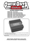
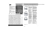
The ADXL345 (used on the ORBIT board) is a small, thin, ultralow power, 3-axis accelerometer with high
resolution (13-bit) measurement at up to ±16 g. It’s functional block diagram is shown in Figure 1. Digital
output data is formatted as 16-bit twos complement and is accessible through either a SPI (3- or 4-wire) or
I2C digital interface. The ADXL345 is well suited for mobile device applications. It measures the static
acceleration of gravity in tilt-sensing applications, as well as dynamic acceleration resulting from motion or
shock. Its high resolution (3.9 mg/LSB) enables measurement of inclination changes less than 1.0°.
Figure 1. Functional Block Diagram for the Accelorometer
Grading Criteria
N/A
Time Required
Approximately one hour
Lab Preparation
It is highly recommended that the student read through this entire procedure once before actually using it as
a tutorial. It is also recommended that the tutorial software was run first to preload compiler options and
source files.
Equipment and Materials
Access to Tiva TM4C123G LaunchPad software and evaluation kit (EK-RM4C123GXL) as well as the
Digilent Orbit board. It is assumed that the student has already completed Lab 3 and the software is
installed properly. Ensure that the boards are plugged in before start of the tutorial.
Software needed
The software requirements from Lab 3 are still applicable here.
Quantity
1
Hardware needed
Quantity
2
The hardware required is the TI Tiva LaunchPad Kit and the Digilent
Corporation’s Orbit Daughter card
1
Additional References
The Evaluation Board user’s manual is on this web site: http://datasheet.octopart.com/EK-TM4C123GXLTexas-Instruments-datasheet-15542121.pdf and the manuals for the Digilent orbit board are located at
http://digilentinc.com/Products/Detail.cfm?NavPath=2,396,1181&Prod=ORBIT-BOOSTER. Here is the
datasheet used for the accelerometer: http://www.analog.com/static/importedfiles/data_sheets/ADXL345.pdf .
COSMIAC tutorials found at: http://cosmiac.org/thrust-areas/academic-programs-and-designservices/education-and-workforce-development/microcontrollers/ate-developed-material/
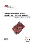
Lab Procedure: Install/Connect board to computer
Figure 2. ARM and ORBIT Combination
This picture of the correct way to mate the Tiva LaunchPad and the Digilent Orbit
boards together. Please do so at this point and connect them as shown in Figure 1.
Figure 3. Code Composer Icon
Launch Code Composer and where prompted, chose the workspaces location to store your project (as shown
in Figure 3).
3
Figure 4. Workspace Selection
Since the installer for the workshop has been run prior to this, the user will be presented with the following
view (Figure 4) where all lab projects exist.
Figure 5. CCS Starting Point
The laboratory material is created to have the students type in a lot of the code. Only by typing the code
and then debugging the errors will a user ever really understand how to do projects. For the sake of this
activity, the source code is provided at the end of the tutorial. In Lab 7, open main.c. Then either type in
all the code from attachment 2 or copy and paste in the code from Attachement 2 into main.c.
4
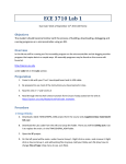
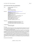
It is now important to spend a couple of minutes to explain a little more about the accelerometer used in this
project. If you are looking on the Orbit board, there is a small chip in the upper right quadrant. It has a
silkscreened cross on the board around the chip with a “X” and “Z” lettering. This is the ADXL345 chip.
Figure 6. ADXL345
As can be seen in Figure 6, it has a 3-axis sensor that can be used to detect the orientation of the board. In
this tutorial, only the X axis will be measured. This is to keep the tutorial as simple as possible. As a result,
the function will have three returned values: -1 (going left), 0 (standing still), or 1 (going right). The chip is
very sensitive. The system transfers data on an I2C line. The ADXL345 has an I2C output and the ARM
processor has I2C inputs as shown in Figure 7 from the datasheet.
Figure 7. Connection Diagram
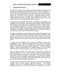
The I2C protocol interface has a unique set of waveforms to allow the system to know when to start and
stop the transfer of data. This waveform timing diagram is shown in Figure 8 and shows how the processor
knows when to receive data.
Figure 8. I2C Waveform Timing Diagram
The entire solution code for this project is given at the end of this tutorial in attachment 2. This initially
looks like a large amount of very complex code however, when you remember that much of the LED
5
portion has been presented in previous labs it is less scary. Add to that the fact that another large portion of
the code is nothing more than delays to slow the system down for human consumption and it is less scary.
Some of the code that is presented in this lab for the first time is shown below:
#define ACCEL_W 0x3A
#define ACCEL_R 0x3B
#define ACCEL_ADDR 0x1D
These three lines above are the definition parameters for the device. They are taken from the ADXL345
datasheet as shown below. It clearly defines the address as x1D, the read as x3B and the write as x3A. The
key to I2C is to remember that it is a very powerful way to attach a wide variety of different sensors onto a
single bus. This bus is also only two wires wide. So, to do this, each device on the bus must have a unique
address. With I2C devices, if you go into their datasheets, it is possible to quickly find their unique
addresses. Some devices often have up to four addresses possible through the use of onboard jumpers.
Figure 9. Datasheet Excerpt
The next set of code shown below is a new topic. It is called a “function prototype.” Most experienced
designers like to have the main starting portion of their code appear at the top of the main.c file. The
beginning of the program is normally identified with “void main(void) {”. To make things cleaner, most
designers will also use the function prototypes to declare the functions at the top of the file and then further
down in the program after the main function, will do the full explanation and declaration of what the
functions actually do. In this case, there are two function prototypes. The first is to initialize the
accelerometer and the second is to read the chip.
The next portion of the code initializes the LEDs. Refer to attachment 3 at the end of this document. Find
the accelerometer and look at what pins are required. This is very similar to what has been done in
previous labs. All peripherals must be initialized before they can be used. The way this code is designed to
operate is to have the LEDs fall or flow downhill based on the way the board is tilted. If the board is tilted
90 degrees to the left, the LEDs will fall down to the bottom. If the board is tilted the other direction, the
LEDs will still attempt to fall to the bottom. After this section of the code, the two functions that were
prototyped earlier are expanded upon.
Open the main.c file that is in the lab installer for Lab 7. When this is compared to the code in attachment 2,
it is clear to see that the code for the LED waterfall is missing. The task of this tutorial is to type on this
6
code. When done, debug/compile and download. Run the program and make sure the LEDs flow
appropriately.
As a challenge exercise, reduce the time to flow the lights from one end to the other or light up the Tiva
board with different color LEDs when extremes are hit.
The start of the main function outlines how to setup a peripheral to be used. The I2C controller is housed
within a GPIO port. Thus setting up the Chip to use this peripheral is a three-step process.
1. Setup the core to enable the I2C hardware. This is part of the SysCtl set of functions outline in the
Driver users guide. The Driver users guide provides an outline of all the available functions found in
the Tiva API
2. Setup the GPIO port to use the I2C controller. This is part of the GPIO set of functions found within
the Driver users guide.
3. Finally, Setup the I2C controller with the settings for the bus you are plugging it into. Like the
UART, I2C has many settings and options. This is part of the I2C set of functions found within the
Driver users guide.
7
Attachment 1: main.c file (starting)
/*******************************************************
Project : Orbit Lab 8 ATE (ACCEL)
Version : 1.0
Date : 2/20/2013
Author : Brian Zufelt / Craig Kief
Company : COSMIAC/UNM
Comments:
This source provides an introduction to the sensing capabilities
for embedded systems. The student will read accelerometer data
and toggle the proper LED to provide tilt measurement
******************************************************
Chip type
: ARM TM4C123GH6PM
Program type
: Firmware
Core Clock frequency
: 80.000000 MHz
*******************************************************/
#define ACCEL_W 0x3A
#define ACCEL_R 0x3B
#define ACCEL_ADDR 0x1D
// Addresses for the accelerometer
// Define needed for pin_map.h
#define PART_TM4C123GH6PM
#include
#include
#include
#include
#include
#include
#include
#include
#include
#include
#include
#include
#include
#include
<stdbool.h>
<stdint.h>
"inc/tm4c123gh6pm.h"
"inc/hw_memmap.h"
"inc/hw_types.h"
"driverlib/gpio.h"
"driverlib/pin_map.h"
"driverlib/sysctl.h"
"driverlib/uart.h"
"inc/hw_i2c.h"
"driverlib/i2c.h"
"inc/hw_ints.h"
"driverlib/interrupt.h"
"driverlib/timer.h"
void Accel_int();
signed int Accel_read();
// Function prototype to initialize the Accelerometer
// Function prototype to read the Accelerometer
void main(void) {
signed short int LED_value = 1;
SysCtlClockSet(SYSCTL_SYSDIV_1 | SYSCTL_USE_OSC | SYSCTL_OSC_MAIN | SYSCTL_XTAL_16MHZ); //setup clock
SysCtlPeripheralEnable(SYSCTL_PERIPH_I2C0);
SysCtlPeripheralEnable(SYSCTL_PERIPH_GPIOB);
// Enable I2C hardware
// Enable Pin hardware
GPIOPinConfigure(GPIO_PB3_I2C0SDA);
GPIOPinConfigure(GPIO_PB2_I2C0SCL);
// Configure GPIO pin for I2C Data line
// Configure GPIO Pin for I2C clock line
GPIOPinTypeI2C(GPIO_PORTB_BASE, GPIO_PIN_2 | GPIO_PIN_3); // Set Pin Type
// Enable Peripheral ports for output
SysCtlPeripheralEnable(SYSCTL_PERIPH_GPIOC);
GPIOPinTypeGPIOOutput(GPIO_PORTC_BASE, GPIO_PIN_6|GPIO_PIN_7); // LED 1 LED 2
DRAIN
GPIOPinTypeGPIOOutput(GPIO_PORTB_BASE, GPIO_PIN_5);
// LED 4
SysCtlPeripheralEnable(SYSCTL_PERIPH_GPIOD);
GPIOPinTypeGPIOOutput(GPIO_PORTD_BASE, GPIO_PIN_6);
// LED 3
//PORTC
//PORT D
//setup the I2C
GPIOPadConfigSet(GPIO_PORTB_BASE, GPIO_PIN_2, GPIO_STRENGTH_2MA, GPIO_PIN_TYPE_STD);
GPIOPadConfigSet(GPIO_PORTB_BASE, GPIO_PIN_3, GPIO_STRENGTH_2MA, GPIO_PIN_TYPE_OD);
8
// SDA MUST BE STD
// SCL MUST BE OPEN
I2CMasterInitExpClk(I2C0_BASE, SysCtlClockGet(), false);
sets the controller to 100kHz communication
Accel_int();
// The False
// Function to initialize the Accelerometer
while(1){
/*
*
*
*
******************************************************************************************************
Fill in this section to read data from the Accelerometer and move the LEDs according to the X axis *
Task: call the Accel_read function and add it to LED_value. Using a number between 1-4 turn on the *
LEDs 1-4 to show tilt in the x axis.
*
********************************************************************************************************/
}
}
void Accel_int(){
// Function to initialize the Accelerometer
I2CMasterSlaveAddrSet(I2C0_BASE, ACCEL_ADDR, false); // false means transmit
I2CMasterControl(I2C0_BASE, I2C_MASTER_CMD_BURST_SEND_START); // Send Start condition
I2CMasterDataPut(I2C0_BASE, 0x2D);
control reg
SysCtlDelay(20000);
// Delay for first transmission
I2CMasterDataPut(I2C0_BASE, 0x08);
Register
// Writing to the Accel
// Send Value to control
I2CMasterControl(I2C0_BASE, I2C_MASTER_CMD_BURST_SEND_FINISH); // Send Stop condition
while(I2CMasterBusBusy(I2C0_BASE)){};
to finish operations
// Wait for I2C controller
}
signed int Accel_read() {
// Function to read the Accelerometer
signed int data;
signed short value = 0;
// value of x
unsigned char MSB;
unsigned char LSB;
I2CMasterSlaveAddrSet(I2C0_BASE, ACCEL_ADDR, false);
// false means transmit
I2CMasterDataPut(I2C0_BASE, 0x32);
SysCtlDelay(20000);
I2CMasterControl(I2C0_BASE, I2C_MASTER_CMD_SINGLE_SEND);
SysCtlDelay(2000000);
// Delay for first transmission
//Request LSB of X Axis
I2CMasterSlaveAddrSet(I2C0_BASE, ACCEL_ADDR, true);
// false means transmit
I2CMasterControl(I2C0_BASE, I2C_MASTER_CMD_SINGLE_RECEIVE);
SysCtlDelay(20000);
//Request LSB of X Axis
LSB = I2CMasterDataGet(I2C0_BASE);
SysCtlDelay(20000);
I2CMasterSlaveAddrSet(I2C0_BASE, ACCEL_ADDR, false);
I2CMasterDataPut(I2C0_BASE, 0x33);
// false means transmit
I2CMasterControl(I2C0_BASE, I2C_MASTER_CMD_SINGLE_SEND);
SysCtlDelay(2000000);
// Delay for first transmission
//Request LSB of X Axis
I2CMasterSlaveAddrSet(I2C0_BASE, ACCEL_ADDR, true);
// false means transmit
I2CMasterControl(I2C0_BASE, I2C_MASTER_CMD_SINGLE_RECEIVE);
SysCtlDelay(20000);
//Request LSB of X Axis
MSB = I2CMasterDataGet(I2C0_BASE);
value = (MSB << 8 | LSB);
// Bit shift MSB the OR it with LSB to get 16-bit value
9
if(value < -250 ){
data = -1;
}
else if (value > 250){
data = 1;
}
// testing axis for value
else{
}
data = 0;
SysCtlDelay(20000);
return data;
// return value
}
10
Attachment 2: main.c file (solution)
/*******************************************************
Project : Orbit Lab 8 ATE (ACCEL)
Version : 1.0
Date : 2/20/2013
Author : Brian Zufelt / Craig Kief
Company : COSMIAC/UNM
Comments:
This source provides an introduction to the sensing capabilities
for embedded systems. The student will read accelerometer data
and toggle the proper LED to provide tilt measurement
******************************************************
Chip type
: ARM TM4C123GH6PM
Program type
: Firmware
Core Clock frequency
: 80.000000 MHz
*******************************************************/
#define ACCEL_W 0x3A
#define ACCEL_R 0x3B
#define ACCEL_ADDR 0x1D
// Addresses for the accelerometer
// Define needed for pin_map.h
#define PART_TM4C123GH6PM
#include
#include
#include
#include
#include
#include
#include
#include
#include
#include
#include
#include
#include
#include
<stdbool.h>
<stdint.h>
"inc/tm4c123gh6pm.h"
"inc/hw_memmap.h"
"inc/hw_types.h"
"driverlib/gpio.h"
"driverlib/pin_map.h"
"driverlib/sysctl.h"
"driverlib/uart.h"
"inc/hw_i2c.h"
"driverlib/i2c.h"
"inc/hw_ints.h"
"driverlib/interrupt.h"
"driverlib/timer.h"
void Accel_int();
signed int Accel_read();
// Function prototype to initialize the Accelerometer
// Function prototype to read the Accelerometer
void main(void) {
signed short int LED_value = 1;
SysCtlClockSet(SYSCTL_SYSDIV_1 | SYSCTL_USE_OSC | SYSCTL_OSC_MAIN | SYSCTL_XTAL_16MHZ); //setup clock
SysCtlPeripheralEnable(SYSCTL_PERIPH_I2C0);
SysCtlPeripheralEnable(SYSCTL_PERIPH_GPIOB);
// Enable I2C hardware
// Enable Pin hardware
GPIOPinConfigure(GPIO_PB3_I2C0SDA);
GPIOPinConfigure(GPIO_PB2_I2C0SCL);
// Configure GPIO pin for I2C Data line
// Configure GPIO Pin for I2C clock line
GPIOPinTypeI2C(GPIO_PORTB_BASE, GPIO_PIN_2 | GPIO_PIN_3); // Set Pin Type
// Enable Peripheral ports for output
SysCtlPeripheralEnable(SYSCTL_PERIPH_GPIOC);
GPIOPinTypeGPIOOutput(GPIO_PORTC_BASE, GPIO_PIN_6|GPIO_PIN_7); // LED 1 LED 2
GPIOPinTypeGPIOOutput(GPIO_PORTB_BASE, GPIO_PIN_5);
// LED 4
SysCtlPeripheralEnable(SYSCTL_PERIPH_GPIOD);
GPIOPinTypeGPIOOutput(GPIO_PORTD_BASE, GPIO_PIN_6);
// LED 3
//PORTC
//PORT D
//setup the I2C
GPIOPadConfigSet(GPIO_PORTB_BASE, GPIO_PIN_2, GPIO_STRENGTH_2MA, GPIO_PIN_TYPE_STD);
GPIOPadConfigSet(GPIO_PORTB_BASE, GPIO_PIN_3, GPIO_STRENGTH_2MA, GPIO_PIN_TYPE_OD);
DRAIN
I2CMasterInitExpClk(I2C0_BASE, SysCtlClockGet(), false);
sets the controller to 100kHz communication
// SDA MUST BE STD
// SCL MUST BE OPEN
// The False
11
Accel_int();
// Function to initialize the Accelerometer
while(1){
// Fill in this section to read data from the Accelerometer and move the LEDs according to the X axis
LED_value = LED_value + Accel_read();
if(LED_value <= 1){
// Cycle through the LEDs on the Orbit board
GPIOPinWrite(GPIO_PORTC_BASE, GPIO_PIN_6|GPIO_PIN_7, 0x40); // LED 1 on LED 2 Of
GPIOPinWrite(GPIO_PORTD_BASE, GPIO_PIN_6, 0x00);
// LED 3 of, Note diferent PORT
GPIOPinWrite(GPIO_PORTB_BASE, GPIO_PIN_5, 0x00);
// LED 4 of
LED_value = 1;
// reset value to maintain range
}
else if(LED_value == 2){
// Cycle through the LEDs on the Orbit board
GPIOPinWrite(GPIO_PORTC_BASE, GPIO_PIN_6|GPIO_PIN_7, 0x80); // LED 1 of LED 2 on
GPIOPinWrite(GPIO_PORTD_BASE, GPIO_PIN_6, 0x00); // LED 3 of, Note diferent PORT
GPIOPinWrite(GPIO_PORTB_BASE, GPIO_PIN_5, 0x00); // LED 4 on
}
else if(LED_value == 3){
// Cycle through the LEDs on the Orbit board
GPIOPinWrite(GPIO_PORTC_BASE, GPIO_PIN_6|GPIO_PIN_7, 0x00); // LED 1 of LED 2 of
GPIOPinWrite(GPIO_PORTD_BASE, GPIO_PIN_6, 0x40); // LED 3 on, Note diferent PORT
GPIOPinWrite(GPIO_PORTB_BASE, GPIO_PIN_5, 0x00); // LED 4 0f
}
else if(LED_value >= 4){
// Cycle through the LEDs on the Orbit board
GPIOPinWrite(GPIO_PORTC_BASE, GPIO_PIN_6|GPIO_PIN_7, 0x00); // LED 1 of LED 2 Of
GPIOPinWrite(GPIO_PORTD_BASE, GPIO_PIN_6, 0x00); // LED 3 of, Note diferent PORT
GPIOPinWrite(GPIO_PORTB_BASE, GPIO_PIN_5, 0x20); // LED 4 on
LED_value = 4;
// reset value to maintain range
}
}
}
void Accel_int(){
// Function to initialize the Accelerometer
I2CMasterSlaveAddrSet(I2C0_BASE, ACCEL_ADDR, false); // false means transmit
I2CMasterControl(I2C0_BASE, I2C_MASTER_CMD_BURST_SEND_START); // Send Start condition
I2CMasterDataPut(I2C0_BASE, 0x2D);
control reg
SysCtlDelay(20000);
// Delay for first transmission
I2CMasterDataPut(I2C0_BASE, 0x08);
Register
// Writing to the Accel
// Send Value to control
I2CMasterControl(I2C0_BASE, I2C_MASTER_CMD_BURST_SEND_FINISH); // Send Stop condition
while(I2CMasterBusBusy(I2C0_BASE)){};
to finish operations
// Wait for I2C controller
}
signed int Accel_read() {// Function to read the Accelerometer
signed int data;
signed short value = 0;
// value of x
unsigned char MSB;
unsigned char LSB;
I2CMasterSlaveAddrSet(I2C0_BASE, ACCEL_ADDR, false);
// false means transmit
I2CMasterDataPut(I2C0_BASE, 0x32);
SysCtlDelay(20000);
I2CMasterControl(I2C0_BASE, I2C_MASTER_CMD_SINGLE_SEND);
SysCtlDelay(2000000);
// Delay for first transmission
12
//Request LSB of X Axis
I2CMasterSlaveAddrSet(I2C0_BASE, ACCEL_ADDR, true);
// false means transmit
I2CMasterControl(I2C0_BASE, I2C_MASTER_CMD_SINGLE_RECEIVE);
SysCtlDelay(20000);
//Request LSB of X Axis
LSB = I2CMasterDataGet(I2C0_BASE);
SysCtlDelay(20000);
I2CMasterSlaveAddrSet(I2C0_BASE, ACCEL_ADDR, false);
I2CMasterDataPut(I2C0_BASE, 0x33);
// false means transmit
I2CMasterControl(I2C0_BASE, I2C_MASTER_CMD_SINGLE_SEND);
SysCtlDelay(2000000);
// Delay for first transmission
//Request LSB of X Axis
I2CMasterSlaveAddrSet(I2C0_BASE, ACCEL_ADDR, true);
// false means transmit
I2CMasterControl(I2C0_BASE, I2C_MASTER_CMD_SINGLE_RECEIVE);
SysCtlDelay(20000);
//Request LSB of X Axis
MSB = I2CMasterDataGet(I2C0_BASE);
value = (MSB << 8 | LSB);
if(value < -250 ){
data = -1;
}
else if (value > 250){
data = 1;
}
else{
// testing axis for value
data = 0;
}
SysCtlDelay(20000);
}
return data;
// return value
13
Attachment 3: Block Diagram of the Pins Used in Projects
14