1
TI ARM Lab 2
Bright Light
National
Science
Foundation
Funded in part, by a grant from the
National Science Foundation
DUE 1068182
Acknowledgements
Developed by Craig Kief, and Brian Zufelt, at the Configurable Space Microsystems Innovations &
Applications Center (COSMIAC). Co-Developers are Bassam Matar from Chandler-Gilbert and Karl Henry
from Drake State. Funded by the National Science Foundation (NSF).
Lab Summary
This is a lab for connecting the hardware the first time. This lab will go through the process of turning on a
single light. This lab was originally developed for the Stellaris LaunchPad and then modified for the Tiva
LaunchPad.
Lab Goal
The goal of this lab is provide sufficient instruction and information so that individuals will be able to
connect the Tiva board for the first time and create a simple project that lights an LED. It will introduce the
user to the building and debugging process within the Code Composer Studio (CCS v6) environment.
Learning Objectives
The student should begin to become familiar with the complier and understand the use of a “main.c” file.
Grading Criteria
N/A
Time Required
Approximately one hour
Lab Preparation
It is highly recommended that the student read through this procedure once before actually using it was a
tutorial. By understanding the final goal it will be easier to use this as a tutorial. This Lab will introduce the
Tiva C Series TM4C123G LaunchPad Evaluation Kit which is a low-cost evaluation platform for ARM®
Cortex™-M4F-based microcontrollers from Texas Instruments. The design of the TM4C123G LaunchPad
highlights the TM4C123GH6PM microcontroller with a USB 2.0 device interface and hibernation module.
The EK-TM4C123GXL evaluation kit also features programmable user buttons and a Red, Green, RGB
LED for custom applications. The stackable headers of the Tiva C Series TM4C123G LaunchPad
BoosterPack XL Interface make it easy and simple to expand the functionality of the TM4C123G
LaunchPad when interfacing to other peripherals with Texas Instruments' MCU BoosterPacks.
Equipment and Materials
Access to Tiva TM4C123 LaunchPad software and evaluation kit (EK-TM4C123GXL). It is assumed that
the student has already completed Lab 1 and the software is installed.
Software needed
The installation files are covered in Lab 1.
Quantity
1
Hardware needed
Quantity
The hardware required is the Tiva LaunchPad Kit. Th kit and the ORBIT
daughter card can be purchased from the Digilent Corporation
www.digilentinc.com
1
Additional References
This page is for general information: http://www.ti.com/tool/ek-tm4c123gxl on the Tiva LauchPad Kit. If
the link above is no longer valid, just google the Tiva LaunchPad and it will pop up.
Lab Procedure 1: Install/Connect board to computer
Step 1: Plug in the supplied USB cable to the top of the Evaluation Kit. Ensure the switch on the board is
set to “DEBUG” and not “DEVICE”.
/*******************************************************
Project : LED LAB 1 ATE
Version : 1.0
Date : 2/20/2013
Author : Brian Zufelt / Craig Kief
Company : COSMIAC/UNM
Comments:
This Code is intended to show how to connect, compile,
a write your first project on the Tiva Launchpad Board
******************************************************
Chip type
: ARM TM4C123GH6PM
Program type
: Firmware
Core Clock frequency : 80.000000 MHz
*******************************************************/
// definitions & Included Files
#include <tm4c123gh6pm.h>
#include <stdint.h>
#define LED_RED 0x02
#define LED_BLUE 0x04
#define LED_GREEN 0x08
void main(void) {
SYSCTL_RCGC2_R = SYSCTL_RCGC2_GPIOF;
// enable PORT F GPIO
GPIO_PORTF_DIR_R = LED_RED|LED_BLUE|LED_GREEN;
// set PORT F as output
GPIO_PORTF_DEN_R = LED_RED|LED_BLUE|LED_GREEN;
// enable digital PORT F
GPIO_PORTF_DATA_R = 0;
// clear all PORT F
GPIO_PORTF_DATA_R = GPIO_PORTF_DATA_R | LED_RED | LED_BLUE | LED_GREEN;
// set LED PORT F
pins high
// loop forever
while(1){
}
}
The source code that will be used in this project is shown above. The code is commented. For now, it is
important to just read through the code and begin to get a feeling for what it does. The purpose of each line
of code will be explained later. Understand that the TI part is designed to be very low power. As such, the
2
user must turn on and activate those parts that will be used. In this case, activation of a single port (port F)
and then turning the port into an output port. Launch Code Composer Studio v6 by double clicking on the
icon shown in figure 1 below.
Figure 1. Code Composer
For those new to CCS 6, the screen shown in Figure 2 is where you begin. This is an excellent resource and
some time should be devoted watching the videos and finding out what is available there. The screen only
appears automatically the first time CCS is launched. After that, to get back to the screen shown in Figure
2, it is necessary to click on Help-> Getting Started.
Figure 2. Start Screen
3
Figure 3. CCS New Project Options
This tutorial uses Eclipse as the Development environment but uses Code Composer as the software
complier. To begin, go to file, new project or click on the new project icon from the getting started screen
shown in Figure 2. For this tutorial project, select the options as shown in Figure 3. These steps identify
the project name. It declares it to be an executable project for our specific version of the ARM processor.
For the purposes of this tutorial, the author chose to name the project “LED” however, any name could have
been chosen. This will create and open for “main.c” file. For most every project that is ever done in the C
code, there will be a main.c and this will be the overarching file for the project. Note that the author also
chose to use a folder in the Temp directory to make the work location.
4
Figure 4. main.c
Figure 5. Replace the project code
Copy all the code from the start of this tutorial and replace the skeleton code that was created in Figure 4.
The designer should now have the design as shown in in Figure 5. As can be seen in the four lines of the
code that does most of the work, there is a lot of reference to port F. To understand how this works, it is
important to first look at the user’s manual for the evaluation kit. The URL for this is currently:
http://www.ti.com/general/docs/lit/getliterature.tsp?baseLiteratureNumber=spmu296&fileType=pdf But, if
this doesn’t work, just google the Tiva LaunchPad Evaluation Board User’s Guide.
5
Figure 6. The User's Manual for the Evaluation Kit
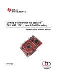
The user should be able to open the pdf shown in Figure 6. This is an excellent resource and should be read
at a later time. For now, skip to the schematics shown in in Figure 7 and 8.
Figure 7. Three LED's in One
The Tiva board that makes up the evaluation kit has an LED on it. Although it is incredibly small, it is
actually three LED in one as shown in Figure 7. This first tutorial will combine the outputs of these three
LEDs to produce a white light.
6
Figure 8. Port F of the Chip
Figure 8 shows how the three LEDs are connected to the processor. They are connected to a port which is
one byte (8 bits) wide. In the code we define red as “0000 0010”; blue as “0000 0100”; and green as “0000
1000”. There are certain requirements for using port F that are taken care of in the first three lines of the
code after void main (void). The first turns on port F. For power saving, it (like all other ports) is powered
down by default. The second sends “1s” to the part which sets it as an output. The third tells port F that it is
digital. The next two lines do the following:
At this point it is best to explain a little more about what is going on with this line of code:
GPIO_PORTF_DATA_R = GPIO_PORTF_DATA_R | LED_RED | LED_BLUE | LED_GREEN
Remember that a “1” turns on an LED. We have three LEDs we want to turn on. First, we set the entire
port F to 0 (all eight bits). Then we do our functions as shown below:
Port F =
Port F =
(Or with)
(Or with)
(Or with)
Port F =
0000
0000
0000
0000
0000
0000
7
0000
0000
0010
0100
1000
1110 (Turns on Red, Green, and Blue)
Figure 9. Building the Project
The next step is to build the project into an executable that will run on the TI chip. Click on ProjectBuild
All. If there are errors then it might be necessary the first time to include projects into your path once. This
would be if there was a question mark next to an include statement. This include is the header file with all
the important (and critical) information about the board. If when you attempt to build the project the first
time, there is an error, it is because it can’t find this file. The next several steps tell it where to look. Go to
ProjectProperties as shown in Figure 10.
Figure 10. Project Properties
8
Figure 11. Adding the path for the .h File
As shown in Figure 11, click on the “Include Options” selection. Click on the “+” symbol to add a directory
path scan to the “inc” directory shown in Figure 11 and click OK. This now adds the included directory to
the path where the board header file is stored so the compiler can find the needed information about the
specific board that is being used.
Figure 12, Debugger
Next, it is time to program the board. Click on Run and then Debug as shown in Figure 12.
9
Figure 13. Stopping at Main
Highlight the main file as shown in Figure 22 and then click “Resume” which looks like a green triangle.
The white light should be on.
Figure 14. Going RED
The final step is to have the light be red instead of white. At this point it is best to explain a little more
about what is going on with this line of code:
GPIO_PORTF_DATA_R = GPIO_PORTF_DATA_R | LED_RED | LED_BLUE | LED_GREEN
Remember that a “1” turns on an LED. We have three LEDs we want to turn on. First, we set the entire
port F to 0 (all eight bits). Then we do our functions as shown below:
or
or
or
0000
0000
0000
0000
0000
0000
0010
0100
1000
1110
10
So, to turn on only Red, I comment out (remove) the other two colors as shown in Figure 23 and rerun. To
rerun, hit the red square, change code, save, debug (little bug symbol) then green triangle again.
11
Attachment 1: main.c solution file
/*******************************************************
Project : LED LAB 2,3 ATE (Launchpad)
Version : 1.0
Date : 2/20/2013
Author : Brian Zufelt / Craig Kief
Company : COSMIAC/UNM
Comments:
This Code is intended to show how to connect, compile,
a write your first project on the Tiva-C Launchpad Board
******************************************************
Chip type
: ARM TM4C123GH6PM
Program type
: Firmware
Core Clock frequency
: 80.000000 MHz
*******************************************************/
#include <tm4c123gh6pm.h>
#include <stdint.h>
// definitions
#define LED_RED 0x02
#define LED_BLUE 0x04
#define LED_GREEN 0x08
// Lab definitions for the 2 versions of the lab
//#define Lab2
#define Lab3
void main(void) {
long unsigned int i = 0;
//general counter
SYSCTL_RCGC2_R = SYSCTL_RCGC2_GPIOF;
// enable PORT F GPIO
GPIO_PORTF_DIR_R = LED_RED|LED_BLUE|LED_GREEN;
// set PORT F as output
GPIO_PORTF_DEN_R = LED_RED|LED_BLUE|LED_GREEN;
#ifdef Lab2
GPIO_PORTF_DATA_R = 0;
// enable digital PORT F
GPIO_PORTF_DATA_R |= LED_RED|LED_BLUE|LED_GREEN;
// clear all PORT F
// set LED PORT F pins high
#endif
// loop forever
while(1){
#ifdef Lab3
GPIO_PORTF_DATA_R = 0;
// clear all PORT F
GPIO_PORTF_DATA_R = LED_GREEN;
// set LED PORT F pins high
for(i=0;i<2500000;i++){};
//delay
for(i=0;i<4000000;i++){};
//delay
GPIO_PORTF_DATA_R = 0;
// clear all PORT F
GPIO_PORTF_DATA_R = LED_GREEN | LED_RED;
// set LED PORT F pins high
12
for(i=0;i<2000000;i++){};
//delay
GPIO_PORTF_DATA_R = 0;
// clear all PORT F
GPIO_PORTF_DATA_R = LED_GREEN | LED_RED;
// set LED PORT F pins high
for(i=0;i<3000000;i++){};
//delay
GPIO_PORTF_DATA_R = 0;
// clear all PORT F
GPIO_PORTF_DATA_R = LED_RED;
// set LED PORT F pins high
for(i=0;i<4000000;i++){};
//delay
#endif
}
}
13
Attachment 2: Block Diagram of the Pins Used in Projects
14
15