1
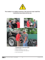
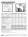
LOADER
MX U303
MX U304
MX U305
MX U306
MX U307
MX U308
MX U309
MX U310
MX U312
User manual
Please read carefully before using MX
loader
UK 366591 AA - 0913
Original instructions
Dear users,
Thanks you for confidence in our product. We are sure it will give you full satisfaction.
By taking a few minutes to read this manual, you will be able to obtain the best results from your MX loader,
extend its lifespan and work in complete safety.
The loader user manual is a very important document, please keep it with you in order to be able to use it if
required. Leave it available to any other user and give it to the next owner of this loader.
Pictures and technical information included in this document may not correspond precisely to your loader; but
the working conditions will be the same.
The loader should be subject to handover from the dealer to the user.
The demonstration of the equipment to be delivered should include:
—
—
—
—
The safety rules.
Hitching and unhitching the loader.
Hitching and unhitching the work implement.
Full use of the controls.
In the event that one of these four necessary items is omitted, you should immediately contact your
dealership.
CONTENTS
1. SAFETY INSTRUCTIONS
6
2. SAFETY STICKERS
7
3. IDENTIFICATION PLATE
8
4. COUNTERWEIGHT
8
5. LOADER UNHITCHING 9
6. LOADER HITCHING 12
7. IMPLEMENT UNHITCHING
14
8. IMPLEMENT HITCHING
16
9. IMPLEMENT CARRIER FRAME MODELS
18
10. IMPLEMENT LEVEL INDICATOR
19
11. FAST-LOCK SYSTEM *
20
12. SHOCK ELIMINATOR SYSTEM *
20
13. SAFETY DEVICE ON LIFTING/CROWDING *
21
14. MAINTENANCE
23
15. GENERAL INFORMATION
24
16. CONTROL
25
17. TECHNICAL SPECIFICATIONS
28
* depending on equipment
The loader is a complex machine. The end user must read this
instruction book before first use.
Familiarise yourself with
—
—
—
—
Safety instructions.
Hitching and unhitching of the loader.
Hitching and unhitching of the implements.
Full use of the controls.
• 19, rue de Rennes • BP 83221 • F - 35690 ACIGNÉ
5
Modification reserved
1. SAFETY INSTRUCTIONS
— Control the loader only from the driver’s seat. Do not let go of the controls until the movements are complete.
— Do not leave the seat before locking the controls to prevent any movement.
— Never leave the tractor while its loader is lifted. Following loader use, park the tractor with the loader lowered to the
ground.
— It is compulsory to ensure that nobody is in the area while the loader is in use (see chapter "SAFETY DEVICE ON
LIFTING/CROWDING")
— The operation must use the implement designed and recommended by MX for the work to be carried out.
— The transport or elevation of persons using the loader is forbidden.
— Ensure tractor stability by using a counterweight. Please check the information regarding the counterweight in this user
manual.
— Restrict all movements while the load is lifted as the tractor may become unbalanced.
— The maximum front axle safe load provided by the tractor’s manufacturer must not be exceeded.
— The maximum front tyres safe load provided by the tyres’s manufacturer must not be exceeded.
— Check regularly tyres pressure.
— Regularly check the presence of safety pins and bolts. Do not replace with any other object such as nails, wire, etc.
— Hitch the loader only to a tractor fitted with a roll-over protective structure (ROPS) or a falling object protective structure
(FOPS). This should be in the protective position when using the loader.
— Watch out for overhead electrical and telephone cables when manoeuvring with the loader in the raised position.
— In compliance with the standard EN 12525, the controls for operating the loader and implements must be of the
"sustained action" type with the exception of the lift floating position which can be maintained in its position by a notching
system.
— Any activity relating to defect investigation (diagnosis) and / or disassembly of parts may only be undertaken by an
accredited professional who shall assure his safety and the protection of the environment in which the actvity is
conducted, in particular in the event of an activity involving the loader staying in the lifted position.
CAUTION !
—
—
—
—
The loader’s hydraulic circuit is designed to have a maximum service pressure of 200 bar.
Never modify hose connections.
The breaking of the seals will result in the cancellation of the MX responsibility for all the equipment supplied.
The assembly of an MX loader which excludes the recommendations in the MX price list in force at the purchase date,
cancels the MX guarantee on all the equipment supplied.
— Any modification to a section of any MX equipment (implements, loader, bracket, etc.) or the use of an implement or
element installed on the MX loader of foreign origin, cancels the MX guarantee for all equipment supplied.
— Use only MX original spare parts. Do not modify your MX loader or its accessories yourself or have another person
modify them (mechanical, electrical, hydraulic, pneumatic characteristics), without prior written agreement from MX.
Failure to respect these regulations may make the loader dangerous. MX will disclaim all responsibility in the event of
damage or injury.
— The guarantee is immediately invalid when the instructions for use, and the MX loader maintenance schedule outlined in
"User Manual" are not observed.
• 19, rue de Rennes • BP 83221 • F - 35690 ACIGNÉ
6
Modification reserved
2. SAFETY STICKERS
Security stickers are located on the loader. Keep them readable and clean, and change them if damaged.
— MX U300 loaders (with AD05 bracket):
3
1
2
526128
4
— MX U300s loaders (with AD90 bracket):
3
1
2
Familiarise yourself with the safety rules in the user manual before using or working on the loader.
Follow the loader hitching and unhitching procedure given in the user manual.
526128
4
Use the anchoring points when handling the loader.
Handling above people is prohibited.
It is prohibited to use the loader and its implements for any other purposes than handling the
materials it was designed for.
• 19, rue de Rennes • BP 83221 • F - 35690 ACIGNÉ
7
Modification reserved
3. IDENTIFICATION PLATE
The identification plate is located inside the LH arm.
19, rue de Rennes F - 35690 ACIGNÉ
Désignation/
Designation
Type / Model / Typ
Poids à vide
Unloaded weight / Leergewicht
Année / Year
kg
328462
N˚ de série
Serial number
Seriennummer
The serial number and loader type which are indicated on this plate might be requested when requiring spare parts or
technical assistance.
4. COUNTERWEIGHT
The stability of the tractor and loader can only be ensured with a counterweight on the rear of the tractor. This
counterweight must ensure that a minimun of 20 % of the total weight (Tractor, loader, implement, maximum load and
counterweight) is applied on the back axle of the tractor in order to work in a safe condition.
Below is the calculation method which indicates the required counterweight (M) (standard EN12525 + A2 2010).
M>
5 N b + I2 (P + N - 5 G)
5 (I1 + I2) - I2
G : Weight on the rear axle, wihtout counterweight, with an empty implement (kg).
G1 : Weight on the front axle, without counterweight, with an empty implement (kg).
b : Distance from the front axle to the implement centre of gravity (mm).
I1 : Distance from rear linkage pins to the rear axle (mm).
I2 : Wheelbase.
N: Usable load of the loader for implement pivot point (A) horizontal with the loader pivot point (B) (kg).
P : G + G1 (kg)
M : Weight of the counterweight (kg).
• 19, rue de Rennes • BP 83221 • F - 35690 ACIGNÉ
8
Modification reserved
5. LOADER UNHITCHING
You will also find a video showing the unhitching/hitching on www.m-x.eu
This operation must be carried out by the driver who must leave the seat and ensure all
manoeuvres are forbidden while he is working on the loader.
The loader must always be coupled to an implement to unhitch
it.
— Choose a flat and stable area.
— Lower the loader with double acting in order to slightly lift the
front axle of the tractor, with the implement horizontal to the
ground. Actuate in notched floating position, then back to
neutral. The lift rams will be filled both sides with oil and
involuntary movements of the loader will be limited when the
loader has prolonged exposure to the sun and will ensure
the hitching is correct.
— Pull the parking brake. Turn off the engine
— Get out of the tractor.
— On the left side, pull the unlocking handle sharply
downwards.
The locking indicator is in the red zone.
MX U300s loaders:
On the left and right hand, unlock taper pin by pulling the
lever forward.
Push the lever upwards with your palm until it engages in
parked position.
— Lower the left and right parking stands.
• 19, rue de Rennes • BP 83221 • F - 35690 ACIGNÉ
9
Modification reserved
— Disconnect the hydraulic’s and electric’s.
Loader with MACH System
— Release the MACH System housing by pushing the
locking pin on the LH side and lifting the handle up.
— Hook the MACH System on the support.
Loader without MACH System
— Close the tap and disconnect the couplings.
— Position the protective covers (clean) to the male and
female couplings. Store the hoses on the loader.
— On the right side, pull the unlocking handle sharply
downwards.
The locking indicator is in the red zone.
• 19, rue de Rennes • BP 83221 • F - 35690 ACIGNÉ
10
Modification reserved
— Return to the driver's cab.
Check on the left and right hitching frames that the locking
indicators are in the red zone.
MX U300 loaders
MX U300s loaders
— Reverse the tractor first with a rapid movement, then more
slowly until the loader rests on its stands
— Check the loader’s stability.
• 19, rue de Rennes • BP 83221 • F - 35690 ACIGNÉ
11
Modification reserved
6. LOADER HITCHING
You will also find a video showing the unhitching/hitching on www.m-x.eu
— Check on the L.H. / R.H. side beams that the locking
indicators are in the red area and that no object will
obstruct the loader hitching.
MX U300 loaders
MX U300s loaders
MX U300 loaders
MX U300s loaders
— The bracket are designed with a roller and a ramp which will
lift the loader when hitching.
— Drive the tractor forward in order to guide the loader frame on
to the brackets until the catches are automatically triggered.
— The loader is locked when indicators are in the green
area.
If the indicators are still in the red zone, refer to
the "Two step hitching" section.
— Connect the hydraulic’s and electric’s.
Loader with MACH System :
— Hold the housing with two hands and using the back of
the housing lift the valve cover and fit the guide bars
vertically into place.
• 19, rue de Rennes • BP 83221 • F - 35690 ACIGNÉ
12
Modification reserved
Loader without MACH System:
— Remove the plastic covers on the couplings.
— Connect the couplings.
— Open the tap.
— Remove L.H. and R.H. side parking stands and place them in
the corresponding side’s cross beam (L.H. in lower part of
cross-beam. R.H. side in the upper part).
— Checking before work :
Press on the ground with an implement to check if loader is
correctly hitched on the tractor. Use D.A. mode.
Two step hitching
1. Connect the hydraulic’s and electric’s 1 .
2. Move the lever forwards to the notched floating position + Moving the tractor forward 2 . If necessary turn the
wheels.
3. Operate lifting movement slightly 3 . The loader is locked (Indicators in the green).
4. Fold the parking stands away.
5. Checking before work : Press on the ground with an implement.
1
3
2
+
• 19, rue de Rennes • BP 83221 • F - 35690 ACIGNÉ
13
Modification reserved
7. IMPLEMENT UNHITCHING
This operation must be carried out by the driver who must leave the seat and ensure all
manoeuvres are forbidden while he is working on the loader.
7.1 Implement carrier with manual unlocking
—
—
—
—
—
Select a stable parking area.
Lower the implement horizontally to 0.30 m from the ground,
Pull on the handbrake,
Turn off the engine,
Decompress the loader’s hydraulic lines feeding the
implement.
NOTA : When loader fitted with one or several solenoid
valves, leave contact on and pressing the buttons.
— Disconnect the hydraulic’s
— MACH 2: disconnect.
— Couplings: disconnect and place plastic caps on the male
and female couplings.
— Place the hoses on the front of the implement.
— Implement unhitching.
From the L.H. side of the loader, pull on the lever to the end.
Never operate from the front of the implement.
• 19, rue de Rennes • BP 83221 • F - 35690 ACIGNÉ
14
Modification reserved
— Pull the lever towards you until it stays engaged.
7.2 FAST LOCK implement frame carrier
— Raise the loader to lift the implement off the ground.
— With the implement horizontal, press the green and orange
buttons while moving the crowd lever to the right (dumping).
The implement is now unlocked.
— Place the implement on the ground by slightly tipping it to
free the implement carrier from the implement.
NOTE : If the implement has one or more hydraulic functions,
firstly disconnect the hoses.
• 19, rue de Rennes • BP 83221 • F - 35690 ACIGNÉ
15
Modification reserved
8. IMPLEMENT HITCHING
This operation must be carried out by the driver who must leave the seat and ensure all
manoeuvres are forbidden while he is working on the loader.
8.1 Implement carrier with manual unlocking
— Check the unlocking lever is in the hitching position (lever
turned backwards). Locking pins are retracted, springs are
compressed.
CAUTION: check implement hoses are away from
hitching area.
— Approach the loader towards the implement.
— Slot onto the implement’s hitching brackets.
— Crowd the implement back while driving forwards until the
unlocking lever is triggered.
— Turn the engine off.
— Decompress the loader’s hydraulic lines feeding the
implement.
NOTE : If the loader is fitted with a solenoid valve, with turned
on the contact and press the control button.
• 19, rue de Rennes • BP 83221 • F - 35690 ACIGNÉ
16
Modification reserved
— Connect the couplers when implement with hydraulic
functions.
8.2 FAST LOCK implement frame carrier
— Before attaching the implement, ensure that the locks are in
the "open" position to allow the implement’s parts to pass.
— Move the loader along the axis of the implement,
Drive the implement carrier into the implement,
Gently crowd and raise the loader to lift the implement from
the ground.
— Press the green and orange buttons by moving the crowd
lever to the left (crowd).
The implement is now locked.
NOTE : If the implement has one or more hydraulic functions,
connect the hoses.
Checking before work:
Press on the ground to check if implement is correctly locked on the loader. Use D.A. mode.
Manoeuvre each hydraulic service to its maximum, in each direction to check the correct
operation of the hydraulic system and that there are no leaks.
• 19, rue de Rennes • BP 83221 • F - 35690 ACIGNÉ
17
Modification reserved
9. IMPLEMENT CARRIER FRAME MODELS
9.1 MX Master-Attach implement carrier frame
9.2 Euro implement carrier frame
9.3 MX Master-Attach / Euro implement carrier frame
To switch from the MX Master-Attach 1 position to the
Euro position 2 ,
— Remove the pins,
2
— Tilt the hitch shoes downwards,
— Ensure that the hitch shoes are kept in position by the
spring rods,
— Put the pins back to their initial position.
1
• 19, rue de Rennes • BP 83221 • F - 35690 ACIGNÉ
18
Modification reserved
9.4 Euro / SMS / ALÖ3 implement carrier frame
To switch from the SMS 1 or ALÖ3 2 position to the
Euro 3 position,
1
— Remove the split pins then the pins,
— Take the hitch shoe and position it by rotating it through
180°,
— Proceed in the same manner for the second hitch shoe.
3
2
9.5 MX Master-Attach / Faucheux-Blanc implement carrier
frame
2
1
To switch from the MX Master-Attach position 1 to the
Faucheux-Blanc position 2 ,
— Remove the hitch shoes from their storage position,
— Fit them in the hitching position and add the 4 attachment
pins,
— Fit the lynch pins to the attachment pins.
10. IMPLEMENT LEVEL INDICATOR
The implement level indicator is useful for implement repositioning. Efficient even while lowering the loader, it is adjustable
depending on the implement type.
Indicator
Implement in position
• 19, rue de Rennes • BP 83221 • F - 35690 ACIGNÉ
19
Modification reserved
11. FAST-LOCK SYSTEM *
The FAST-LOCK System (*optional) on the implement carrier
allows tools to be hitched and unhitched without hydraulic or
electrical operation from the driver's cab.
1
Locked position 1 .
Released position 2 .
2
12. SHOCK ELIMINATOR SYSTEM *
Shocks are eliminated when moving the loader or when
it stops suddenly when being lowered (* option).
This system softens jolting on the tractor and therefore
jarring in the cab.
The Shock Eliminator can be isolated using the valve
1 .
1
Without
SHOCK ELIMINATOR
The Shock Eliminator can be enabled or disabled
directly from the cab.
• 19, rue de Rennes • BP 83221 • F - 35690 ACIGNÉ
20
With
SHOCK ELIMINATOR
Modification reserved
13. SAFETY DEVICE ON LIFTING/CROWDING *
This device is essential for working when people are present near the load (*option).
In compliance with the EN 12525 + A2 2010 standard, it can be disengaged for working when no one is near the load.
The movements can then be carried out, with no loss of power or speed of execution.
Unique, this equipment is compatible with the Shock Eliminator and the notched floating position.
13.1 Extract from the Front Loaders standard EN12525 + A2 2010:
"4.4.4 Protection against unintended lowering
If the front loader is also designed for lifting operations requiring the presence of someone near the load when the loader
is in raised position, the hydraulic circuit of the lifting arm cylinders must be fitted with a safety device in compliance with
Annex E, with the aim of preventing unintended lowering of the lifting arm, and which must remain active in the event of
rupture of the power supply of the control circuit.
If this safety device can be put in on/off or enabled/disabled positions for operations that do not require the presence of
someone near the load, then the following additional specifications apply:
– it must be possible to put the safety device into on/off or enabled/disabled position from the driver's cab;
– it must be possible to put the safety device into on or enabled position from the ground and not be near the load;
– the control for putting the safety device into off or disabled position must be designed and located so that the operator
cannot actuate it unintentionally;
– the status (on/off or enabled/disabled) of the safety device must be clearly indicated and clearly visible from the driver's
cab and from the loading area.
In compliance with 7.1.2, the correct operating method must be explained, including the warnings, in the instruction
manual.
The loader must be fitted with a warning informing that for lifting operations requiring the presence of someone near the
load, when the loader is in raised position, the safety device must be in the on position (actuated) (see 7.2).
Information for using front loaders that are not designed for lifting operations requiring the presence of an operator near
the load when the loader is in raised position must comply with 7.1.4 and 7.2."
"Annex E (normative)
Test method and acceptance criteria for means to avoid unintended lowering
E.1 Terms and definitions
E.1.1
discharge device
hydraulic valves used to simulate a rupture of the loader's hydraulic piping.
E.1.2
test load
weight (50 ± 10)% of nominal lifting capacity specified by the manufacturer of the loader.
E.2 Test procedure
The test specified from E.2.1 to E.2.2 must be carried out according to each of the following conditions:
– position held after lowering the test load to a height of (1 ± 0.1) m (static test);
– position held after lifting the test load to a height of (1 ± 0.1) m (static test);
and at oil temperatures of the hydraulic system between 40°C and 50°C.
E.2.1 The discharge device between the lifting rams and the control valve must be open.
E.2.2 Complete lowering of the load must be measured at the implement's pivot point.
E.3 Acceptance criterion
Complete lowering measured in E.2.2, during the first 10 seconds must not exceed:
– 100 mm, in the event of a stop or manual disabling of the safety device;
– 300 mm, in the case of a continuously actuated safety device.
After 5 min, lowering must not exceed an additional 100 mm."
• 19, rue de Rennes • BP 83221 • F - 35690 ACIGNÉ
21
Modification reserved
13.2 Use
The hydraulic circuit of the lifting and bucket rams is fitted with a
safety device 1 and 2 .
By default, the safety device is actuated.
As soon as the user presses the button in the cab 3 (secure
button) the safety device is disabled and the red indicator lights
come on:
– the button in the cab 3 ,
– the external button 4 ,
– the two solenoid valve connectors of the lifting rams 5 .
2
1
5
Button function 3 :
– Press (A): safety device disabled.
– Press (B): safety device actuated.
3
A
CAUTION : disabling the safety device is only authorised when
nobody is near the load. In this case, the floating position held
and the Shock Eliminator are compatible.
By pressing buttons 3 or 4 , the safety device is
automatically actuated (red lights off).
Note : As soon as the tractor is switched off, the safety device is
automatically actuated.
B
The button 4 is used exclusively to reactivate the safety
device from the outside.
In this case, the red indicator lights go off.
4
• 19, rue de Rennes • BP 83221 • F - 35690 ACIGNÉ
22
Modification reserved
14. MAINTENANCE
Change the tractor hydraulic oil and filters regularly in accordance with the tractor
manufacturer recommendations. Used oil does not lubricate, it also contributes to the
damage of all hydraulic components (pump, valves, rams…). Even clear oil may not
lubricate.
For any maintenance operations made whilst the loader is the raised position, the loader must be locked into position.
Two possibilities :
— Lock the joystick in the cab (see chapter "Control")
or,
— Disconnection of the MACH System if loader has one, or closing the tap fitted on the lifting coupler if the loader is without
MACH System (see chapter "Loader unhitching").
When using a high presssure cleaner, do not direct water towards the electrical components.
Clean the implement and the loader front after each use. The acid
from slurry, fertilisers and silage is harmful to paint, steel and the
machine’s pivot points.
Grease every 10 hours and after each wash (grease eliminates
water) and particularly after washing with a high pressure cleaner.
Check the following each month, and more frequently when used intensively:
— Condition of the loader articulations. If necessary, replace the wear bushes and/or the pins.
— The wear bushes must be replaced if they are less than 1 mm thick.
— The tractor’s hydraulic oil level and the sealing of the hydraulic system. If you notice any internal or external leaks on the
hydraulic parts (rams, hoses, connectors, Mach, couplings, etc.), contact your dealer.
— Condition of the hoses: replace them if you notice any small cracks or oil.
— Correct operation of the monolever (cables, play, locking, etc.).
— Condition of the electric wiring. Please contact your dealer if there is any damage to connectors or cables.
— Mechanical condition (any cracking, deformation, fretting on stops, play, parking stands, etc.).
Please contact your dealer if there is any abnormal wear.
• 19, rue de Rennes • BP 83221 • F - 35690 ACIGNÉ
23
Modification reserved
Check the tightness of the bracket after 10, 50 hours then every 100 hours or when carring out tractor maintenance. In
case of untightness, please contact your dealer.
IMPORTANT:
All the screws needing to be retightened must be inspected, changed if necessary, cleaned and smeared with loctite.
Tighten the screws to the tightening torque specified in the table below.
Use of a pneumatic spanner to tighten the screws on the tractor is forbidden.
Tightening torque (Nm)
Thread
M8
M 10
M 12
M 14
M 16
M 18
M 20
M 22
M 30 x 150
M 40 x 150
Class of bolt
10.9
29
58
101
160
245
340
475
640
8.8
21
42
72
114
174
240
340
455
500
500
12.9
35
70
121
193
295
405
570
765
15. GENERAL INFORMATION
— Each implement is designed for a specific use and has its own resistance limits.
— Land clearing and stump extraction are forbiden. Such work should be carried out by a specialist vehicle and is not
possible for an agricultural loader.
— Use the tractor’s power to enter in the material to be moved rather than approaching it with speed, which will generate
high stress on tractor and loader.
— When the load to be manoeuvred is too heavy, do not apply force to the hydraulic components. This also applies when
rams are fully closed or extended. Please release the control lever.
— When ground levelling, work at a slow speed with the
implement at a maximum angle of 50° with respect to the
ground.
50˚ max
Operate with flexibility and in a judicious manner.
• 19, rue de Rennes • BP 83221 • F - 35690 ACIGNÉ
24
Modification reserved
16. CONTROL
Important: Never leave the tractor with loader in raised position.
All spool valves produce an internal leak required for correct
operation.
16.1 On tractor valves :
Please report to the tractor’s instruction book.
16.1.1 Front/rear control selector (option) :
From the original joystick of the tractor, the operator can control the
MX loader or the rear couplers from the cab.
Front/rear control selector (option)
16.2 Control with MX PROPILOT control valve
16.2.1 Handle setting *
To ensure comfortable control over the loader, you can set the
position of the handle.
* on Propilot and Flexpilot controls only.
• 19, rue de Rennes • BP 83221 • F - 35690 ACIGNÉ
25
Modification reserved
16.3 Control with MX PROPILOT control valve
16.3.1 Security
Involuntary loader manoeuvre can be avoided. The PROPILOT
joystick can be locked.
Move the unlocking lever (1).
— (A): released position.
— (B): locked position.
1
A
B
16.3.2 Movements
Y
X
First function: along "Y" axis
— Forwards = loader lowered
(Double action of the hydraulic ram).
— Forwards after notch = floating position
(Single action of the hydraulic ram).
— Backwards = loader raised.
Second function: along "X" axis
— To the left = implement crowding.
— To the right = implement dumping.
Y
X
Third function: along "X" axis
— Button (1) + crowding or dumping movement.
3
Fourth function: along "X" axis
— Button (2) + crowding or dumping movement.
2
1
FAST-LOCK
Automatic hitching/unhitching of the implement.
— Button (1) + (4) + crowding or dumping movement.
Note :
Button (3) not used.
Button (4) only available in the case of the FAST-LOCK option.
• 19, rue de Rennes • BP 83221 • F - 35690 ACIGNÉ
26
4
Modification reserved
16.4 Control with MX FLEXPILOT control valve
16.4.1 Security
Involuntary loader manoeuvre can be avoided. The FLEXPILOT
joystick can be locked.
Turn the isolating thumbwheel (1):
— (A): released position.
— (B): locked position.
1
A
16.4.2 Movements
Y
First function: along "Y" axis
— Forwards = loader lowered
(Double action of the hydraulic ram).
— Forwards after notch = floating position
(Single action of the hydraulic ram).
— Backwards = loader raised.
B
X
Second function: along "X" axis
— To the left = implement crowding.
— To the right = implement dumping.
Y
X
Third function: along "X" axis
— Button (1) + crowding or dumping movement.
3
Fourth function: along "X" axis
— Button (2) + crowding or dumping movement.
2
1
FAST-LOCK
Automatic hitching/unhitching of the implement.
— Button (1) + (4) + crowding or dumping movement.
Note :
Button (3) not used.
Button (4) operational only in the case of the FAST-LOCK option.
4
16.5 Control with MX TECHPILOT control valve
Please refer to Techpilot instruction book.
• 19, rue de Rennes • BP 83221 • F - 35690 ACIGNÉ
27
Modification reserved
17. TECHNICAL SPECIFICATIONS
4
2 1
5
3
U303 - U304
U305 - U306
U307 - U308
U309 - U310
U312
Length (A)
2,25 m
2,30 m
2,40 m
2,50 m
2,60 m
Width (B)
1,18 m
1,18 m
1,18 m
1,18 m
1,18 m
Without parallelogram
U303 : 1,66 m
U305 : 1,72 m
U307 : 1,77 m
1,83 m
–
With parallelogram
U304 : 1,78 m
U306 : 1,84 m
U308 : 1,88 m
1,94 m
1,98 m
Without parallelogram
U303 : 400 Kg
U305 : 445 Kg
U307 : 475 Kg
U309 : 510 Kg
–
With parallelogram
U304 : 455 Kg
U306 : 500 Kg
U308 : 520 Kg
U310 : 575 Kg
U312 : 595 Kg
Maximum height at implement pivot *
3,50 m
3,75 m
3,85 m
4,00 m
4,15 m
Maximum height under horizontal bucket (1) #
3,25 m
3,50 m
3,60 m
3,75 m
3,90 m
Maximum height under dumped bucket (2) #
2,70 m
2,95 m
3,05 m
3,20 m
3,35 m
Digging depth (3) #
0,20 m
0,20 m
0,20 m
0,20 m
0,20 m
Dumping angle at maximum height (4) #
52 °
52 °
55 °
55 °
55 °
Crowd angle (5) #
47 °
47 °
47 °
47 °
47 °
Lift force at implement pivo *
1600 Kg
1900 Kg
2100 Kg
2400 Kg
2400 Kg
Lift capacity at implement pivot over the entire lifting range *
1400 Kg
1500 Kg
1900 Kg
2200 Kg
2200 Kg
Height (C)
Weight (Without option)
Payload on pallet 0.60 m in front of the forks
At ground level
At 2 m height
At 3 m height
At maximum height
Without parallelogram
U303 : 950 Kg
U305 : 1150 Kg
U307 : 1750 Kg
U309 : 1600 Kg
–
With parallelogram
U304 : 1180 Kg
U306 : 1400 Kg
U308 : 1650 Kg
U310 : 1780 Kg
1825 Kg
Without parallelogram
U303 : 970 Kg
U305 : 1000 Kg
U307 : 1650 Kg
U309 : 1550 Kg
–
With parallelogram
U304 : 1220 Kg
U306 : 1380 Kg
U308 : 1650 Kg
U310 : 1780 Kg
1825 Kg
Without parallelogram
U303 : 850 Kg
U305 : 900 Kg
U307 : 1550 Kg
U309 : 1525 Kg
–
With parallelogram
U304 : 1200 Kg
U306 : 1350 Kg
U308 : 1650 Kg
U310 : 1780 Kg
1825 Kg
Without parallelogram
U303 : 870 Kg
U305 : 860 Kg
U307 : 1500 Kg
U309 : 1500 Kg
–
With parallelogram
U304 : 1180 Kg
U306 : 1350 Kg
U308 : 1650 Kg
U310 : 1780 Kg
1825 Kg
Lifting time
3.3 s
3.8 s
4.6 s / 5.4 s
5.4 s
5.4 s
Dumping time
1.4 s
1.4 s
1.9 s
1.9 s
1.9 s
Specifications measured at 190 bar and a flow rate of 60 l/min.
Data varies depending on the type of tractor used.
# Indicated data are with a loose material bucket.
* Values at ground level and at implement pivot are not considered to be working data.
• 19, rue de Rennes • BP 83221 • F - 35690 ACIGNÉ
28
Modification reserved
• 19, rue de Rennes • BP 83221 • F - 35690 ACIGNÉ
29
Modification reserved
DECLARATION OF CONFORMITY
We, the manufacturers :
MX
19,Rue de Rennes
F - 35690 Acigné
Declare that the products:
MX U303, MX U304, MX U305, MX U306, MX U307, MX U308, MX U309, MX U310, MX
U312 loaders
MX U303s, MX U304s, MX U305s, MX U306s, MX U307s, MX U308s, MX U309s, MX
U310s, MX U312s loaders
Comply with standard EN 12525 + A2 2010, which presupposes compliance with the
requirements of directive 2006/42 EC of the European Parliament and of the Council
of 17 May 2006 on machinery.
Acigné, the 2nd of September 2013.
Loïc Mailleux
Technical Manager
19, rue de Rennes
BP 83221
F - 35690 ACIGNE
Tel.: +33 (0)2 99 62 52 60
Faks: +33 (0)2 99 62 50 22
E-mail: [email protected]