1
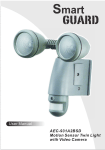
User Manual
AEC-931A2BS
Motion Sensor Twin Light
with Warning Message
Table of contents
1. Contents of package ...................................................................Page 1
2. Smartguard™ Motion Light with Video Camera .......................Page 3
3. Assembly ....................................................................................Page 3
4. Installation ..................................................................................Page 4
5. Programming your Smartguard™...............................................Page 7
6. Technical Specifications .............................................................Page 8
7. General Information and Safety..................................................Page 9
8. FCC information.........................................................................Page 10
Contents of packaging
Smartguard™ Motion Light with Video Camera
User Manual
2pc 100W JCD G8 bulb
Accessory bag: 2pcs screws, 2pcs plastic masonry plugs, wall
mount (cross bar), 3pcs wire nuts
(User manual are kept in one zip bag, please keep these accessories.)
1
①
③
②
User Manual
AEC-931A2BSD
Motion Sensor Twin Light
with Video Camera
SmartguardTM
JCD G8 bulb
⑤
④
Screws
Plastic
Masonry plugs
⑥
Screw D
Wall Mount
(Cross Bar)
User Manual
⑦
Wire nuts
2
Smartguard™ Motion Light with Video
Camera overview
15
Floodlight cover
15
90
Halogen bulb
90
50
50
PIR lens
45
45
35
Fig. 1
Fig. 2
Step 1. Assembly
1. Install/replace the halogen bulb (see fig. 3)
Make sure to unplug unit or turn off power first.
Remove floodlight cover by twisting cover anticlockwise.
If replacing a bulb, take out the existing halogen light bulb
(part no. ②)
Put in new 100 Watt maximum JCD G8 bulb (part no. ②).
Replace floodlight cover.
* Caution: Never touch the bulbs with your bare hands.
Always use a clean cloth when handling the bulbs.
Fig. 3
3
Step 2. Installing the Smartguard™ Motion
Light with Video Camera
IMPORTANT
IF IN ANY DOUBT ABOUT THE INSTALLATION OF THIS PRODUCT, CONSULT A
QUALIFIED ELECTRICIAN
- This product must be grounded
- Do not mount the unit against inflammable surfaces
- The motion detector will not operate correctly if it is installed:
1 Near the outlet of a central heating boiler
2 Near air conditioning plant
3 Pointing directly at moving vehicles
4 Within sight of reflections from moving water
5 Where other lamps could shine on the detector
BEFORE ATTEMPTING ANY INSTALLATION OR MAINTENANCE, ENSURE THAT
THE ELECTRICAL SUPPLY IS SWITCHED OFF AND THE CIRCUIT FUSES
REMOVED OR THE CIRCUIT BREAKER IS IN THE OFF POSITION.
Please make sure the voltage and polarity are correct before connection.
Incorrect voltage may cause electric shock. If you are not sure, please
contact your retailer.
Note: It is recommend to mount Smartguard™ Motion Light with
Video Camera 6 – 7ft above the ground for optimum performance,
do not mount the fixture below 3.94ft. See below figure for details of
performance range.
Detection range: 32.8ft x 180° (see fig. 4)
Fig. 4
4
Installation to a junction box using crossbar mount
(see fig. 5 & fig. 6):
1. Attach the crossbar (part no. ⑥) to junction box and fix by screw C.
2. Feed the cable through the back mounting plate.
3. Fix the mounting plate to crossbar (part no. ⑥) by screw D
4. Connect the black wire (live wire) from the AC power cord to the
single black wire coming from SmartguardTM using one of the supplied
wire nuts (part no. ⑦).
5. Connect the white wire from the AC power cord to the white wire
coming from SmartguardTM using one of the supplied wire nuts (part
no. ⑦).
6. Connect the green/yellow wire from the AC power cord to the 2
green/yellow wires coming from SmartguardTM using one of the
supplied wire nuts (part no. ⑦).
7. Make sure the polarity is correct.
8. Attach the unit to the mounting plate. You will first need to angle the
unit back so that the catch at the top of the mounting plate fits into slot
on the back of the unit. Next lower the unit until holes at the bottom of
the mounting plate and unit are flush. Then screw (screw A) into this
hole, tightening carefully.
Screw D
Screw C
Screw A
Fig. 5
5
AC power cord
White
N
L
Black
Screw A
Fig. 6
Installing your Smartguard™ Motion Light with Video
Camera on surface without a junction box.
(see fig. 6 & fig. 7)
1. Place plastic masonry plugs (part no. ⑤) into desired surface aligning
holes as shown below. Using an electric screwdriver, fasten mounting
plate directly to surface using screws E (part no. ④).
2. Feed the cable through the back mounting plate.
3. Connect the black wire (live wire) from the AC power cord to the
single black wire coming from Smartguard using one of the supplied
wire nuts (part no. ⑦).
4. Connect the white wire from the AC power cord to the white wire
coming from Smartguard using one of the supplied wire nuts (part no
⑦).
5. Connect the green/yellow wire from the AC power cord to the 2
green/yellow wires coming from Smartguard using one of the supplied
wire nuts (part no. ⑦).
6. Make sure the polarity is correct.
7. Attach the unit to the mounting plate. You will first need to angle the
unit back so that the catch at the top of the mounting plate fits into slot
on the back of the unit. Next lower the unit until holes at the bottom of
the mounting plate and unit are flush. Then screw (screw A) into this
hole, tightening carefully.
6
Fig. 7
Please allow 1 minute warm-up time after switching on.
Step 3. Adjusting the Settings (see fig. 8~9)
Time control:Turn the
time control knob to”+” side
to increase the illumination
time (7 minutes max.), turn
the control knob to “-“ side
to reduce the illumination
time (30 seconds min.).
Screw A
Fig. 8
Sensitivity control:Adjust the detector range of Passive
Infrared Motion Sensor (± 6.56ft ~ 32.8ft)
Selecting working mode:
Mode 1: Suggested setting when out of town
- Light + speaker: all day detection
- Daytime and nighttime: light and speaker are all in operation
Mode 2: Suggested for day to day use
- Light at night + speaker in the daytime
- Daytime: light is off, speaker is on
- Nighttime: light is on, speaker is off
7
Mode 3: Perfect for a place of business
- Light at night + speaker at night
- Daytime: light is off, speaker is off
- Nighttime: light is on, speaker is on
Audio mode: for selecting which audio message will play
when motion sensor detects movement.
- Pre-set default is “You are trespassing”
- Push one time for “Warning! You are being videotaped by a
security camera”
- Push again for “dog barking”
- Push one more time to turn off this function
3 Position Switch
Fig. 9
Technical Specifications
1. Features and specification:
PIR detection angle 180 Deg and detection range up to 32.8ft
Powered by AC 100V to 240V(subject to requirement)
Halogen bulb JCD G8 100W*2
Auto light sensor.
Sensitivity control
Floodlight time delay control
8
General Information and safety
Special care instructions!!!
The Smartguard Motion Sensor Twin Light is designed to be
weather resistant. Never attempt to immerse the unit in water or any
other liquid. This will damage the unit and void the warranty.
This product is designed to illuminate and make
verbal announcements. It will not prevent the commission of any
act, legal or illegal. The manufacturer assumes no liability for
any damage to property, injury to person, or death.
Remove dirt or stains with a soft cloth dampened with water or
neutral detergent. Keep the Smartguard™ Motion Sensor Twin
Light in a dry and cool dust-free environment or container when it
is NOT used
Do not open the Smartguard™ Motion Sensor Twin Light with for
unauthorized service. This could cause serious damage to the unit
and will void the warranty.
This Smartguard™ Motion Sensor Twin Light is a precision
electronic device. Do not attempt to service this unit, as opening or
removing covers may expose you to the danger of electric shock or
other risks.
To avoid risk of burns due to high temperature do not touch the
floodlight when it is turned on.
CAUTION!!!
9
FCC Information
This device complies with Part 15 of the FCC Rules. Operation is subject
to the following two conditions: (1) This device may not cause harmful
interference, and (2) This device must accept any interference received,
including interference that may cause undesired operation.
Warning: Changes or modification to this unit not expressly approved by
the party responsible for compliance could void the user’s authority to
operate the equipment.
NOTE: This equipment has been tested and found to comply with the
limited for Class B digital device, pursuant to Part 15 of the FCC Rules.
Their limits are designed to provide reasonable protection against harmful
interference in a residential installation. This equipment generates, uses
and can radiate radio frequency energy and, if not installed and used in
accordance with the instructions, may cause harmful interference to radio
communications.
However, there is no guarantee that interference will not occur in a
particular installation. If the equipment does cause harmful interference to
radio or television reception, which can be determined by turning the
equipment off and on, the user is encouraged to try to correct the
interference by one or more of the following measures: Reorient or
relocate the receiving antenna.
Increase the separation between the equipment and receiver.
Connect the equipment into an outlet on a circuit different from that to
which the receiver is connected.
Consult the dealer or an experienced radio/TV technician for help.
10