1
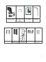
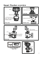
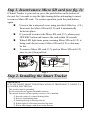
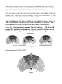
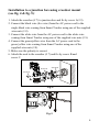
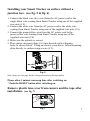
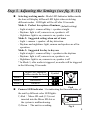
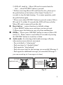
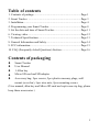
Table of contents
1. Contents of package ...................................................................Page 1
2. Smart Tracker ............................................................................Page 3
3. Installation ..................................................................................Page 4
4. Programming your Smart Tracker ..............................................Page 8
5. Set the date and time of Smart Tracker.......................................Page 11
6. Viewing video.............................................................................Page 12
7. Technical Specifications .............................................................Page 13
8. General Information and Safety..................................................Page 14
9. FCC information.........................................................................Page 15
10. FAQ (Frequently Asked Questions) Section ............................Page 16
Contents of packaging
Smart Tracker
User Manual
1 Allen key
Micro SD card and SD adaptor
Accessory bag: 2pcs screws, 2pcs plastic masonry plugs, wall
mount (cross bar), 3pcs wire nuts, 2pcs mounting screws
(User manual, allen key and Micro SD card are kept in one zip bag, please
keep these accessories.)
1
①
④
③
②
User Manual
S mart Tr ack er In te llig ent
M oti on Se nsor
Tr ack ing Ligh t
Smart Tracker
Micro SD Card
&
SD adaptor
⑥
⑤
Screws
Plastic
Masonry plugs
⑦
Wall Mount
(Cross Bar)
User Manual
Allen Key
⑧
Wire nuts
Mounting
screws
2
Smart Tracker overview
RESET
OFF/REC
LED
TIME/DATE SET
Top view
Camera
3 motion sensors
Mode push-button
Mode LED Indicator
(hidden inside)
Speaker
Front view
Bottom view
LED indicator
Waterproofed cover
LCD
AUDIO MODE
PLAY/ERASE
SET/REC
MIC
Side view
0
25
Left 70
Right 70
Camera adjustable
down 25°
3
Step 1. Insert/remove Micro SD card (see fig. 1):
If Smart Tracker is powered on, press the push-button on the bottom of
the unit for 3 seconds to stop the light turning before attempting to insert
or remove Micro SD card. To resume operation, push the push-button
again.
Unscrew the waterproof cover using provided Allen key (# 4),
then insert the Micro SD card (# 2) until it automatically
locks into place.
If you need to remove the Micro SD card (# 2), please press
OFF/REC button and remove the card within 30 seconds.
When LED light turns green, meaning Micro SD card (# 2) is
being read, do not remove Micro SD card (# 2) or data may
be lost.
To remove Micro SD card (# 2), push in Micro SD card (# 2)
once to eject, then pull out.
LED light
Micro SD card slot
Fig. 1
Step 2. Installing the Smart Tracker
IMPORTANT
IF IN ANY DOUBT ABOUT THE INSTALLATION OF THIS PRODUCT, CONSULT A
QUALIFIED ELECTRICIAN
- This product must be grounded
- Do not mount the unit against flammable surfaces
- The motion detector will not operate correctly if it is installed:
1 Near the outlet of a central heating boiler
2 Near air conditioning plant
3 Pointing directly at moving vehicles
4 Within sight of reflections from moving water
5 Where other lamps could shine on the detector
4
* BEFORE ATTEMPTING ANY INSTALLATION OR MAINTENANCE, ENSURE
THAT THE ELECTRICAL SUPPLY IS SWITCHED OFF AND THE CIRCUIT FUSES
REMOVED OR THE CIRCUIT BREAKER IS IN THE OFF POSITION.
* PLEASE MAKE SURE THE VOLTAGE AND POLARITY ARE CORRECT BEFORE
CONNECTION. INCORRECT VOLTAGE MAY CAUSE ELECTRIC SHOCK. IF YOU
ARE NOT SURE, PLEASE CONTACT YOUR RETAILER.
* DO NOT REMOVE THE TAPE UNTIL YOU FINISH THE INSTALLATION. IF
THE TAPE COMES OFF THE LIGHT, PLEASE REPLACE IT OR HOLD THE
LIGHT HEAD TO AVOID SWIVELING AND DAMAGE THE PRODUCT.
Note: It is recommended to mount Smart Tracker 6 – 7ft above the
ground for optimum performance, do not mount the fixture below
3.94ft. See below figure for details of performance range.
TOP VEW
GOOD SENSITIVITY
LESS SENSITIVITY
Fig. 2
Detection range: 32.8ft x 210°
Fig. 3
5
Installation to a junction box using crossbar mount
(see fig. 4 & fig. 5):
1. Attach the crossbar (# 7) to junction box and fix by screw A(# 9).
2. Connect the black wire (live wire) from the AC power cord to the
single black wire coming from Smart Tracker using one of the supplied
wire nuts (# 8).
3. Connect the white wire from the AC power cord to the white wire
coming from Smart Tracker using one of the supplied wire nuts (# 8).
4. Connect the green/yellow wire from the AC power cord to the
green/yellow wire coming from Smart Tracker using one of the
supplied wire nuts (# 8).
5. Make sure the polarity is correct.
6. Attach the unit to the crossbar (# 7) and fix by screw B and
screw C.
Screw B
Screw A
GN D
Screw C
Fig. 4
Fig. 5
6
Installing your Smart Tracker on surface without a
junction box. (see fig. 5 & fig. 6)
1. Connect the black wire (live wire) from the AC power cord to the
single black wire coming from Smart Tracker using one of the supplied
wire nuts (# 8).
2. Connect the white wire from the AC power cord to the white wire
coming from Smart Tracker using one of the supplied wire nuts (# 8).
3. Connect the green/yellow wire from the AC power cord to the
green/yellow wire coming from Smart Tracker using one of the
supplied wire nuts (# 8).
4. Make sure the polarity is correct.
5. Place plastic masonry plugs (# 6) into desired surface aligning
holes as shown below. Using an electric screwdriver, fasten mounting
plate directly to surface using screws (# 5).
Fig. 6
Note: please see last page for the wiring instruction for Europe market
Please allow 1 minute warm-up time after switching on.
* Push the RESET button after switching on.
Remove plastic lens cover from camera and the tape after
installation. (see fig. 7)
Fig. 7
7
Step 3. Adjusting the Settings (see fig. 8~11)
Selecting working mode : Mode LED Indicator hidden inside
the lens will display different LED lights when switching
different modes. LED light will be off after 30 seconds.
Mode 1: Perfect for a place of business (default setting)
- Light at night + camera all day + speaker at night
- Daytime: light is off, camera is on, speaker is off
- Nighttime: light is on, camera is on, speaker is on
Mode 2: Suggested setting when out of town
- Light + camera + speaker: all day detection
- Daytime and nighttime: light, camera and speaker are all in
operation
Mode 3: Suggested for day to day use
- Light at night + camera all day + speaker in the daytime
- Daytime: light is off, camera is on, speaker is on
- Nighttime: light is on, camera is on, speaker is off
* In Mode 3, after audio is triggered, no audio will be triggered
in the following 30 seconds.
Mode LED Indicator
(hidden inside the lens)
Mode 1
RED
Mode 2
ORANGE
Mode 3
GREEN
Symbol
this
Fig.8
Camera LED indicator:for indicating the function status of
the unit by different color LED lights.
1) Red: Micro SD card (# 2) is not
inserted into the Micro SD slot or
the system is malfunctioning.
this
2) Green: The unit is recording.
Fig. 9
8
3) LED off: stand by(Micro SD card is inserted into the
slot), when OFF/REC button is pressed.
* Before removing Micro SD card from the slot, please press
the push-button on the bottom of the Smart Tracker for 3
seconds to stop the light turning. To resume operation, push
the push-button again.
* Please note when OFF/REC button is pressed, remove Micro
SD card (# 2) within 30 seconds (the LED will turn red after
Micro SD card is removed from the slot)
Reset button: restore functions to default settings
1) Press RESET button once each time you turn on unit.
2) Please press this button in case of system malfunction.
Off/Rec:Please press OFF/REC button to remove Micro SD
card (# 2). Please remove card within 30 seconds of pressing
the OFF/REC button to avoid loss of data.
Audio mode: for selecting which audio message will play
when motion sensor detects movement.
- Pre-set default is “silent mode”
- Push one time for “doorbell chime”
- Push again for “dog barking”
- Push one more time for the message you recorded (Message 1)
- Push again for additional message you recorded (Message 2 you can record up to 2 messages at a time)
OFF/REC
RESET
AUDIO MODE
SET/REC
PLAY/ERASE
TIME/DATE SET
MIC
Fig. 10
Fig. 11
9
Step 4. Recording Audio Messages (see fig. 11)
1. Press the SET/REC button for 3 seconds, and you will hear a
single beep. After the beep, start recording your message by
talking into the microphone (see fig. 11). Push the button again
to stop recording, and you will hear a series of 2 beeps, meaning
the recording is finished. If you do not push the button again
after you have recorded the message, the recording will stop
automatically after 10 seconds.
2. Smart Tracker can hold 2 self-recorded messages. If you have
recorded one message, repeat above step for message 2.
3. If you hear a series of 3 beeps when you want to record your
message by pressing the SET/REC button for 3 seconds, this
means the self-recorded messages are full, please erase previous
messages.
Play/Erase : allows you to listen to and erase messages
(see fig. 11)
i.
If you have only recorded 1 message, push the button one
time to listen to recorded Message 1. If you wish to erase it,
press the PLAY/ERASE button and hold it for 3 seconds.
You will hear a series of 2 beeps, indicating the message has
been erased.
ii. If you have recorded 2 messages, push the button one time
to listen to the first message, and push it again to listen to
the second message. If you want to erase a message, select
that message, and after listening to it, push the
PLAY/ERASE button and hold it for 3 seconds to erase it.
iii. If message 1 is erased, message 2 will automatically become
message 1. The next message you record will then become
the new message 2.
10
Step 5. Set the Date and Time:
This will allow the security video taken by Smart Tracker to display
the correct date and time it was taken.
TIME/DATE SET
1. Push TIME/DATE SET button (see fig.
OFF/REC
14) for 3 seconds. The LCD screen will
LCD
then flash 3 times, indicating you have
entered Time/Date setting mode.
2. “YEAR”setting:”Y” and “08” are
displayed on the screen; push the button
to set year from “08-99”, push the
Fig. 12
button again and hold for 3 seconds to scroll through numbers quickly.
If you have not pressed the button for 3 seconds, it will automatically
save the year and go on to allow you to set the month.
3. Repeat the same setting procedure for MONTH/DATE/HOUR/MINUTE.
4. “VIDEO/PHOTO ”setting:when entering this mode, these two
icons
and “V” appear on the screen;push the button to
choose ”V”(Video)or ”P”(Photo). If you have not pushed any
buttons for 3 second, “OK” will appear on the screen, indicating it has
automatically saved the current settings. The LCD screen will shut off
automatically 10 seconds later.
* On the ”P” (photo) setting, Smart Tracker will take a series of digital
photographs at a rate of 3 photos every second when the motion sensor is
triggered
①
③
⑤
⑦
Start
②
MONTH ④
Setting
HOUR ⑥
Setting
VIDEO/ ⑧
PHOTO
Setting
YEAR
Setting
DATE
Setting
MINUTE
Setting
Finish
11
Step 6. Viewing video
1. Viewing image by computer through a card reader (see fig. 13)
Open the waterproof cover on the Smart Tracker.
Press OFF/REC button and remove Micro SD card (# 2) from
the slot.
Put the Micro SD card (# 2) into a card reader, connect card
reader to computer, and open any media player to view the
video.
Fig. 13
12
Technical Specifications
1. Features and specification:
PIR detection angle 210 Deg and detection range up to 32.8ft
Records 20 seconds image recording for image stream:
10fps at 640*480 Pixels
Built in Micro SD card slot for Micro SD memory card
Micro SD card slot for additional storage, max memory size
up to 2G
Micro SD card spec.: FAT
Automatic exposure control, white balance and sharpness
Auto Date & Time stamp
Effective viewing angle:60 deg
Effective viewing distance: 26.24 feet
Image format: JPEG AVI File
Powered by AC 100V to 240V(subject to requirement)
8pcs 1W Nichia super power white LED
Auto light sensor.
Lifetime of stepper motor: 20,000 times turning
Product measurements:(L) 6.28” x (W) 6.77” x (H) 11.22”
Net weight: 1.2kgs
13
General Information and safety
Special care instructions!!!
The Smart Tracker is designed to be weather resistant. Never
attempt to immerse the unit in water or any other liquid. This will
damage the unit and void the warranty.
This product is designed to illuminate, video, and make
verbal announcements. It will not prevent the commission of any
act, legal or illegal. The manufacturer assumes no liability for
any damage to property, injury to person, or death.
Use a soft lens cloth for cleaning lens. Avoid touching lens with
fingers.
Remove dirt or stains with a soft cloth dampened with water or
neutral detergent. Keep the Smart Tracker in a dry and cool dustfree environment or container when it is NOT used
Do not open the Smart Tracker for unauthorized service. This could
cause serious damage to the unit and will void the warranty.
This Smart Tracker is a precision electronic device. Do not attempt
to service this camera yourself, as opening or removing covers may
expose you to the danger of electric shock or other risks.
14
FCC Information
This device complies with Part 15 of the FCC Rules. Operation is subject
to the following two conditions: (1) This device may not cause harmful
interference, and (2) This device must accept any interference received,
including interference that may cause undesired operation.
Warning: Changes or modification to this unit not expressly approved by
the party responsible for compliance could void the user’s authority to
operate the equipment.
NOTE: This equipment has been tested and found to comply with the
limited for Class B digital device, pursuant to Part 15 of the FCC Rules.
Their limits are designed to provide reasonable protection against harmful
interference in a residential installation. This equipment generates, uses
and can radiate radio frequency energy and, if not installed and used in
accordance with the instructions, may cause harmful interference to radio
communications.
However, there is no guarantee that interference will not occur in a
particular installation. If the equipment does cause harmful interference to
radio or television reception, which can be determined by turning the
equipment off and on, the user is encouraged to try to correct the
interference by one or more of the following measures: Reorient or
relocate the receiving antenna.
Increase the separation between the equipment and receiver.
Connect the equipment into an outlet on a circuit different from that to
which the receiver is connected.
Consult the dealer or an experienced radio/TV technician for help.
15
FAQ (Frequently Asked Questions) Section
Q. How many pictures does the Micro SD card hold?
A: The number of video files that amount to 1GB varies, as the size in
bytes of each 20-second video clip will vary depending on the amount of
brightness, color, and movement in each video clip. The clips typically
vary from 2MB to 8MB.
Micro SD Card
1G
1G
2G
2G
File Size
2Mb
8Mb
2Mb
8Mb
Q’ty of File(approx.)
500
125
1000
250
Q. What happens when the card is full?
A: Smart Tracker will automatically return to the oldest file and save over
it each time a new video clip is stored. That means you don’t have to take
out the Micro SD card unless you wish to review or save the video files.
Q. Can I transfer pictures from the camera via cable?
A: No, you can’t. If your computer has an SD card slot, you may insert
the Micro SD card directly into the computer and access the files by going
to My Computer and opening the removable for the Micro SD card,
which should appear when you insert the card. See Step. 6 “Viewing
video” in your instruction manual for details. If you don’t have an SD
card slot, you may purchase an SD card reader from any retailer that sells
electronics. Once you have an SD card reader, simply insert the card into
the reader and attach the reader to your computer using a USB slot (not
included in this packaging), and access the data the same way as
explained above.
16
Q. Can I view a live image of what the camera sees?
A: No, you can’t. There is no USB port available with Smart Tracker.
Q. What does that mean if the hidden LED flashes in orange light?
A: The LED flashes in orange light indicating the stepper motor of Smart
Tracker is now in abnormal status, the light may stop turning
automatically. Please simply switch off /on the main power to resume the
Smart Tracker. Make sure you push OFF/REC first to stop recording
before switching off the main power. Below are the possible abnormal
situations:
- External force: the light head is blocked by objects or is blown by strong
wind and is unable to turn properly. The hidden LED indicator will
flash in orange to signal users the abnormal situation.
- Stepper motor: when stepper motor is going to be out of its lifetime or is
damaged, the hidden LED indicator will flash in orange to signal users
the abnormal situation.
* If the stepper motor stops working due to lifetime limit, the Smart
Tracker becomes a regular motion sensor security light.
17