1
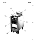
RC6700
15” Ruggedized Industrial PC
HAR15PFA03-48018-R01
Hardware Manual
HAR15PFA03-48018-R01 Hardware Manual
1
The information provided in this documentation contains general descriptions and/or technical
characteristics of the performance of the products contained herein. This documentation is not
intended as a substitute for and is not to be used for determining suitability or reliability of these
products for specific user applications. It is the duty of any such user or integrator to perform
the appropriate and complete risk analysis, evaluation and testing of the products with respect
to the relevant specific application or use thereof. Neither Pro-face nor any of its affiliates or
subsidiaries shall be responsible or liable for misuse of the information contained herein. If you
have any suggestions for improvements or amendments or have found errors in this publication,
please notify us.
No part of this document may be reproduced in any form or by any means, electronic or
mechanical, including photocopying, without express written permission of Proface.
All pertinent state, regional, and local safety regulations must be observed when installing
and using this product. For reasons of safety and to help ensure compliance with documented
system data, only the manufacturer should perform repairs to components.
When devices are used for applications with technical safety requirements, the relevant
instructions must be followed.
Failure to use Pro-face software or approved software with our hardware products may result in
injury, harm, or improper operating results.
Failure to observe this information can result in injury or equipment damage.
Copyright © 2015 Digital Electronics Corporation. All Rights Reserved.
PLEASE NOTE
Electrical equipment should be installed, operated, serviced, and maintained only by
qualified personnel. No responsibility is assumed by Pro-face for any consequences
arising out of the use of this material.
A qualified person is one who has skills and knowledge related to the construction and
operation of electrical equipment and its installation, and has received safety training
to recognize and avoid the hazards involved.
HAR15PFA03-48018-R01 Hardware Manual
2
Table of Contents
Safety Information............................................................................................................................................................ 4
Important Information.....................................................................................................................................................6
Device Overview.................................................................................................................................................................9
Physical Overview............................................................................................................................................................10
Package Contents.....................................................................................................................................................10
Product Overview...................................................................................................................................................... 11
Front View.............................................................................................................................................................. 11
Side and Rear Views.......................................................................................................................................... 11
LED Indicators..................................................................................................................................................... 12
Hardware Specification................................................................................................................................................. 12
Mechanical Dimensions................................................................................................................................................. 15
System Mounting to a Sub Frame or Panel Mount......................................................................................... 16
Panel Mount................................................................................................................................................................. 16
Mounting Guide......................................................................................................................................................... 17
VESA Mount...............................................................................................................................................................20
Getting Started................................................................................................................................................................. 21
Turning on the Device............................................................................................................................................. 21
Adjusting the LCD Display Brightness.......................................................................................................... 22
Calibrating Touch Screen..................................................................................................................................... 23
Installation.......................................................................................................................................................................... 27
Wiring Requirements............................................................................................................................................. 27
Connecting the interface...................................................................................................................................... 28
Connecting to Other Devices............................................................................................................................ 29
Connector Pin Assignments...............................................................................................................................30
BIOS Setup Utility........................................................................................................................................................... 33
When to Use............................................................................................................................................................... 33
Starting BIOS Setup Utility................................................................................................................................. 33
How to Use.................................................................................................................................................................. 33
BIOS Menu...................................................................................................................................................................34
Maintenance..................................................................................................................................................................... 40
System Recovery............................................................................................................................................................ 40
Pro-face Support.............................................................................................................................................................. 41
New Product Satisfaction Return............................................................................................................................ 41
HAR15PFA03-48018-R01 Hardware Manual
3
Safety Information
Read these instructions carefully, and look at the equipment to become familiar with the device
before trying to install, operate, or maintain it. The following special messages may appear
throughout this documentation or on the equipment to warn of potential hazards or to call
attention to information that clarifies or simplifies a procedure.
The addition of this symbol to a Danger safety label indicates
that an electical hazard exists, which will result in personal
injury if the instructions are not followed.
This is the safety alert symbol. It is used to alert you to
potential personal injury hazards. Obey all safety messages
that follow this symbol to avoid possible injury or death.
DANGER
DANGER indicates an imminently hazardous situation which, if not avoided,
will result in death or serious injury.
WARNING
WARNING indicates a potentially hazardous situation which, if not avoided,
can result in death or serious injury.
CAUTION
CAUTION indicates a potentially hazardous situation which, if not avoided,
can result in minor or moderate injury.
NOTICE
NOTICE is used to address practices not related to physical injury.
Warning! Always completely purge all explosive gases from the work area, then disconnect the
power cord from your chassis whenever you work with the hardware. Do not make connections
while the power is on. Sensitive electronic components can be damaged by sudden power surges.
Only experienced electronics personnel should open the PC chassis.
Caution! Always ground yourself to remove any static charge before touching the CPU card.
Modern electronic devices are very sensitive to static electric charges. As a safety precaution, use
a grounding wrist strap at all times. Place all electronic components in a static-dissipative surface
or static-shielded bag when they are not in the chassis.
HAR15PFA03-48018-R01 Hardware Manual
4
Safety Precautions
• Please read these safety instructions carefully.
• Please keep this user’s manual for later reference.
• Please disconnect this equipment from any AC outlet before cleaning. Do not use liquid or spray
detergents for cleaning. Use a damp cloth.
• For pluggable equipment, the power outlet must be installed near the equipment and must be
easily accessible.
• Keep this equipment away from humidity.
• Put this equipment on a reliable surface during installation. Dropping it or letting it fall could
cause damage.
• The openings on the enclosure are for air convection and to protect the equipment from
overheating. DO NOT COVER THE OPENINGS.
• Make sure the voltage of the power source is correct before connecting the equipment to the
power outlet.
• Position the power cord so that people cannot step on it. Do not place anything over the
power cord.
• All cautions and warnings on the equipment should be noted.
• If the equipment is not used for a long time, disconnect it from the power source to avoid
damage by transient over-voltage.
• Never pour any liquid into an opening. This could cause fire or electrical shock.
• Never open the equipment. For safety reasons, only qualified service personnel should open
the equipment.
• If any of the following situations arises, get the equipment checked by service personnel:
o The power cord or plug is damaged.
o Liquid has penetrated into the equipment.
o The equipment has been exposed to moisture.
o The equipment does not work well or you cannot get it to work according to the user’s manual.
o The equipment has been dropped and damaged.
o The equipment has obvious signs of breakage.
• Do not leave this equipment in an uncontrolled environment where the storage temperature is
below -20° C (-4°F) or above 60° C (140° F). It may damage the equipment.
HAR15PFA03-48018-R01 Hardware Manual
5
• CAUTION: Use the recommended mounting apparatus to avoid risk of injury.
• WARNING: Only use the connection cords that come with the product. When in doubt, please
contact the manufacturer.
• WARNING: Ground against electrostatic damage to the device by taking the following
preventive steps:
o Cover workstations with approved anti-static material. Use a wrist strap connected to
a work surface and properly grounded tools and equipment.
o Use anti-static mats, heel straps, or air ionizer for added protection.
o Handle electrostatic-sensitive components, PCB’s and assemblies by the case or
the edge of the board.
o Avoid contact with pins, leads, or circuitry.
o Turn off power and input signals before inserting and removing connectors or
test equipment.
o Keep the work area free of non-conductive materials, such as ordinary plastic assembly
aids and Styrofoam.
o Use filed service tools, such as cutters, screwdrivers, and vacuum cleaners that are
conductive.
o Always lay drivers and PCB’s with the component side down on anti-static foam.
Intended Use
15” Full IP65 Stainless flat touch series are primarily intended for use in Hazardous areas. They are
suitable for use in oil, gas, and petrochemical manufacturing and others where ignitable gases or
vapor may be present. This device is typically used for automation or control purposes.
Important Information
Federal Communications Commission Radio Frequency Interface Statement – For USA
This device complies with part 15 FCC rules.
Operation is subject to the following two conditions:
• This device may not cause harmful interference.
• This device must accept any interference received including interference that
may cause undesired operation.
This equipment has been tested and found to comply with the limits for a class “A” digital device,
pursuant to part 15 of the FCC rules. These limits are designed to provide reasonable protection
against harmful interference when the equipment is operated in a commercial environment. This
equipment generates, uses, and can radiate radio frequency energy and, if not installed and used in
accordance with the instruction manual, may cause harmful interference to radio communications.
Operation of this equipment in a residential area is likely to cause harmful interference in which
case the user will be required to correct the interference at him own expense.
HAR15PFA03-48018-R01 Hardware Manual
6
Certifications and Standards
Agency Standard for Marking
Description
Explosive Atmospheres Directive
II 3 G Ex ic nA IIC Gc
Certification with ATEX Directive 94/9/EC;
Independent 3rd party assessment (Notified Body:
DEMKO) DEMKO 15 ATEX 1522U EN 60079-0: 2012
/ EN 60079-11: 2012 / EN 60079-15: 2010 Standards
N. A. Safety for Information Technology Equipment
I.T.E.
E320439
I.T.E. for Use in
Hazardous Locations
E365958
Certification by Underwriter’s Laboratories to
UL60950-1, 2nd Edition standard and equivalent
CSA C22.2 No 60950-1-07, 2nd Edition Standard
N. A. Safety for Hazardous Locations Class I, Div. 2,
Groups A, B, C, D, T4
Certification by Underwriter’s Laboratories to ANSI/
ISA- 12.12.01 -2012 standard and equivalent CAN/
CSA C22.2 No 213-M1987 Standard
Self-Declaration in accordance with European LVD
Directive 2006/95/EC; Independent 3rd party
assessment (Accredited by IEC 17025)
Self-Declaration in accordance with EMC Directive
2004/108/EC; Independent 3rd party assessment
(Accredited by IEC 17025)
Schedule of Limitations
• Subject devices have not been evaluated to the enclosure requirements for the required
protection method. The enclosure of the device must be evaluated as part of end product
evaluation or installed in an enclosure that provides a degree of protection not less than IP 54 in
accordance with EN 60079-15. Subject devices are for use in an area of not more than pollution
degree 2 in accordance with IEC 60664-1.
• Subject devices are for use in -20°C to +50°C. During temperature test, the highest measured
temperature within the device was 105.9°C at 50ºC service temperature.
HAR15PFA03-48018-R01 Hardware Manual
7
• Service temperature was determined during the maximum surface temperature tests.
The below table indicates the service temperature of critical components:
Component
Service Temperature Range (°C)
Membrane Keypad
-20 to 70
Touchscreen Overlay (PET)
-20 to 69
Gasket Between Front and Rear Cover
-20 to 74
• Subject devices have been evaluated as a Low Power Apparatus regarding clearances, creepage
distances and separation requirements; the devices are intended for installation in an area of not
more than pollution degree 2 in accordance with IEC 60664-1 and an IP54 minimum enclosure.
• The power adapter was not evaluated with the devices to use in Hazardous Location.
Trademark Acknowledgement
Brand and product names are trademarks or registered trademarks of their respective owners.
Disclaimer
We reserves the right to make changes, without notice, to any product, including circuits and/or
software described or contained in this manual in order to improve design and/or performance.
We assume no responsibility or liability for the use of the described product(s), conveys no
license or title under any patent, copyright, or masks work rights to these products, and makes no
representations or warranties that these products are free from patent, copyright, or mask work
right infringement, unless otherwise specified. Applications that are described in this manual are
for illustration purposes only. We make no representation or guarantee that such application will
be suitable for the specified use without further testing or modification.
Warranty
Our warranty guarantees that each of its products will be free from material and workmanship
defects for a period of one year from the invoice date. If the customer discovers a defect, we will,
at his/her option, repair or replace the defective product at no charge to the customer, provide
it is returned during the warranty period of one year, with transportation charges prepaid. The
returned product must be properly packaged in its original packaging to obtain warranty service.
If the serial number and the product shipping data differ by over 30 days, the in-warranty service
will be made according to the shipping date. In the serial numbers the third and fourth two digits
give the year of manufacture, and the fifth digit means the month (e. g., with A for October, B for
November and C for December). For example, the serial number 1W14Axxxxxxxx means October
of year 2014.
HAR15PFA03-48018-R01 Hardware Manual
8
Customer Service
We provide a service guide for any problem by contacting with your distributor, sales
representative, or our customer service center for technical support if you need additional
assistance. You may need the following information ready before you call:
• Product serial number
• Peripheral attachments
• Software (OS, version, application software, etc.)
• Description of complete problem
• The exact wording of any error messages
In addition, free technical support is available from our engineers every business day. We are
always ready to give advice on application requirements or specific information on the installation
and operation of any of our products. Please do not hesitate to call (800-289-9266) or e-mail us
([email protected]).
Device Overview
This 15” Hazardous Areas Classified Locations HMI Panel PC has a footprint of 15.6 x 12.2 inches
and is less than two inches thick. The sturdy stainless steel housing has anti-corrosion protection
and carries an IP65/NEMA4 sealing rating, meaning that it’s completely protected against dust,
and also protected against low-pressure water jets from all directions. The very wide -4 to
122 degree Fahrenheit operating temperature range means the panel can be deployed almost
anywhere.
This device is suitable for deployment in certain hazardous locations where flammable substance
may be present. Specifically, the device is certified for use in Class 1, Division 2, Groups A through
D (i.e. Acetylene, Hydrogen, Ethylene, and Propane) classified areas and surface temperatures
not exceeding 275o Fahrenheit (135o Celsius) in the US market, and ATEX Gas Zone 2 Classified
areas in European and other markets.
HAR15PFA03-48018-R01 Hardware Manual
9
Physical Overview
Package Contents
Before using this Panel PC, please make sure that all the items listed below are
present in your package:
HAR15PFA03-48018-R01 Hardware Manual
10
Front View
Side and Rear Views
HAR15PFA03-48018-R01 Hardware Manual
11
LED Indicators
LED Type
Status
Description
On
Power is On.
Off
Power is Off.
Blinking
Power
Storage activity (data is being read or written).
Storage
Off
System is idle.
Hardware Specification
Item
Specifications
Computer
CPU
Intel Dual Core Atom N2600 1.60 GHz processor
OS
Windows Embedded Standard 7 P
System Chipset
Intel NM10
Bios
AMI 16Mbit Flash
System Memory
4 GB capacity, 4 GB pre-installed
USB
2 x USB 2.0, M21 connector
Storage
Storage Support
HAR15PFA03-48018-R01 Hardware Manual
32 GB industrial graded SSD; support up to 256 GB
12
Hardware Specification
Item
Specifications
Display
Panel Size
15-inch 1024 x 768, 1000nit LED backlight LCD
Contrast Ratio
700:1
Response Time
8ms
View Angles
Horizontal: 160 degree (left to right)
Vertical: 140 degree (up to down)
Max Colors
16.2 M colors
Video Output
VGA output, M21 connector
Resolution
VGA: 640 x 480
SVGA: 800 x 600
XGA: 1024 x 768
Touch
ELO Flat Resistive single point touch, suitable for use
outdoors around heavy equipment
Ethernet Interface
Hardware Interface
M12 connector
LAN
1 x 10/100/1000 Mbps port
Serial Interface
Serial Standard
1 x RS232/RS422/RS485 port, pre-selectable by jumper
Connector Type
M12 connector
Power Requirements
Input Voltage
Typical 24V DC
External 100 to 240 VAC isolated power supply unit
Connector
M21 connector
Power Consumption
Typical 25 W (Maximum backlight and high CPU load)
HAR15PFA03-48018-R01 Hardware Manual
13
Hardware Specification
Item
Specifications
Environment Consideration
Operating Temperature
-20 to 60°C (-4 to 140°F)
Storage Temperature
-20 to 60°C (-4 to 140°F)
Ambient Relative Humidity
10 to 95% (non-condensing)
Anti-Vibration
MIL-STD-810G Method 514.6
Anti-Shock
MIL-STD-810G Method 516.6
Physical Characteristics
Housing
Stainless steel
Weight
9.5 kg (21 lbs.)
Dimensions
396 x 310 x 49 mm (15.59 x 12.20 x 1.93 in)
Mounting
Panel mount and mounting holes for VESA 100
HAR15PFA03-48018-R01 Hardware Manual
14
Mechanical Dimensions
15” Dimensions
HAR15PFA03-48018-R01 Hardware Manual
15
System Mounting to a Sub Frame or Panel Mount
Panel Mount
Note that customer needs to provide their own opening enclosure. To mount the
device to the enclosure, do the following:
1. Prepare the cut out following this dimension
2. Screw from the back through the opening and mount the unit, make sure that the
rubber in the right position to give IP protection
From Front View
HAR15PFA03-48018-R01 Hardware Manual
From Rear View
*Red line represents IP54 rubber
16
Mounting Guide
For 10mm IP65 Panel PC
- Panel is aligned with the same height of the front of the open fram metal housing.
- Customers can fix our Panel PC with their fixture by M3 screws.
- VESA mount holes are also available for mounting from back side.
Side View
Rear View
HAR15PFA03-48018-R01 Hardware Manual
17
Mounting Guide
For 10mm IP65 Panel PC
HAR15PFA03-48018-R01 Hardware Manual
18
Mounting Guide
For 10mm IP65 Panel PC
HAR15PFA03-48018-R01 Hardware Manual
19
VESA Mount
• Dimensions: 75 x 75mm
• Screw Hole Diameter: M4 x 5mm
• Direction: Compatible with swinging arms mounting kits.
HAR15PFA03-48018-R01 Hardware Manual
20
Getting Started
Turning on the Device
1. Remove the protective cap of the DC IN Jack.
2. Plug the AC adapter to the DC-in jack of your device. Make sure the cable
fits to the connector, then tighten the O-ring (by turning it clockwise) to
secure the connection.
3.
Connect the AC adapter to the power cord.
4.
Plug the power cord to an electrical outlet.
5.
Plug the Power button to turn on the device.
Note: When the system hangs, press the Reset button to restart the device
HAR15PFA03-48018-R01 Hardware Manual
21
Adjusting the LCD Display Brightness
1. Tap the arrow on the system tray to display the hidden icons
2. Double-tap the
icon to display the brightness menu
3. Drag the brightness bar to adjust the brightness level according to your preference.
HAR15PFA03-48018-R01 Hardware Manual
22
Calibrating Touch Screen
When turning on the Panel PC for the first time, it is highly recommended to calibrate the touch
screen to ensure touch accuracy.
Five-wire resistive touch screen
The five-wire resistive touch screens use a glass panel with a uniform resistive coating. A
thick polyester coversheet is tightly suspended over the top of the glass, separated by small,
transparent insulating dots. The coversheet has a hard, durable coating on the outer side and a
conductive coating on the inner side.
When the screen is touched, the conductive coating makes electrical contact with the coating
on the glass. The voltages produced are the analog representation of the position touched. The
controller digitizes these voltages and transmits them to the computer for processing. The fivewire technology utilizes the bottom substrate for both X and Y-axis measurements. The flexible
coversheet acts only as a voltage-measuring probe. This means the touchscreen will continue
working properly even with non-uniformity in the cover sheet’s conductive coating. The result is an
accurate, durable and reliable touchscreen that offers drift free operation. The touchscreens are
sealed against contamination and moisture. The coversheet is sealed to the glass substrate with an
industrial grade caulk. This prevents wicking of fluid between the coversheet and glass. Also, the
touchscreens are not air vented, thereby preventing fluid ingress through an air vent.
HAR15PFA03-48018-R01 Hardware Manual
23
Brief Specification
Subject
Details
Input Method
Finger, gloved hand, or stylus activation
Positional Accuracy
Standard deviation error is less than 0.080 (2 mm)
Resolution
Touch point density is based on controller resolution
Touch Activation Force
Typically less than 4 ounces (113 grams)
Light Transmission
HL products: 80% +/–5% at 550 nm wavelength
of 4096 x 4096
Enhanced products: 60% +/–5% at 550 nm wavelength
Update touch-screen driver or new information. Go to www.elotouch.com.
Elo Touch Correction
Elo Touch driver software provides a consistent software interface among all ELO touch screens
and controllers. Go to http://www.elotouch.com/Support/dnld.asp for a complete list of available
supports. After the driver installation is complete, do the following to perform touch screen
calibration.
1. Tap the arrow on the system tray to display the hidden icons.
2. Double-tap the
icon to display the Elo Touchscreen menu.
HAR15PFA03-48018-R01 Hardware Manual
24
3. Double-tap the
icon to proceed to next step.
4. Follow the on-screen instructions to calibrate the touch screen.
HAR15PFA03-48018-R01 Hardware Manual
25
5. Tap the
icon if the cursor follows your finger to finish and exit the
calibration utility
HAR15PFA03-48018-R01 Hardware Manual
26
Installation
Wiring Requirements
The following common safety precautions should be observed before installing any
electronic device:
• Strive to use separate, non-intersecting paths to route power and networking wires. If power
wiring and device wiring paths must cross make sure the wires are perpendicular at the
intersection point.
• Keep the wires separated according to interface. The rule of thumb is that wiring that shares
similar electrical characteristics may be bundled together.
• Do not bundle input wiring with output wiring. Keep them separate.
• When necessary, it is strongly advised that you label wiring to all devices in the system.
ATTENTION
• Do not run signal or communication wiring and power wiring in the same conduit. To avoid
interference, wires with different signal characteristics (i.e., different interfaces) should be routed
separately.
• Be sure to disconnect the power cord before installing and/or wiring your device.
• Verify the maximum possible current for each wire gauge, especially for the power cords.
Observe all electrical codes dictating the maximum current allowable for each wire gauge.
• If the current goes above the maximum ratings (80 W), the wiring could overheat, causing
serious damage to your equipment.
• Be careful when handling the unit. When the unit is plugged in, the internal components
generate a lot of heat which may leave the outer casing too hot to touch.
HAR15PFA03-48018-R01 Hardware Manual
27
Connecting The Interface
This Panel PC comes with various interfaces located on the bottom panel. All of these
connectors have been shipped with protective caps and tethers. If you wish to detach the
tethers, the screws securing them to the bottom panel will need to be removed. To ensure the
waterproof function can work properly, make sure that the protective caps and the tethers have
been securely fastened whenever the connectors are not used.
IMPORTANT
Please note that when reinstalling the protective cap, it must be fully tightened to ensure the unit
is properly sealed to meet the IP65 enclosure rating.
HAR15PFA03-48018-R01 Hardware Manual
28
Connecting To Other Devices
Perform the connections as shown below.
HAR15PFA03-48018-R01 Hardware Manual
29
Connector Pin Assignments
This Display is equipped with four connectors which are IP65 level and fool-proofing design. Use
only the cables that are included in the package.
The pin assignments of the cables are as follows:
• Input cables size 18AWG minimum, and minimum temperature rating of the cables is 105°C.
HAR15PFA03-48018-R01 Hardware Manual
30
HAR15PFA03-48018-R01 Hardware Manual
31
HAR15PFA03-48018-R01 Hardware Manual
32
BIOS Setup Utility
When to Use
You need to run BIOS Setup utility when:
• You see an error message on the screen requesting that you run BIOS Setup utility.
• You want to restore the factory default BIOS settings.
• You want to modify some specific hardware settings.
• You want to modify some specific settings to optimize the system performance.
Starting BIOS Setup Utility
A USB keyboard is required to access, move around, and make selections in the BIOS Setup Utility.
1. Before turning on the Tablet Computer, connect the USB keyboard to the USB port of the
Tablet Computer.
2. Power on the Tablet Computer.
3. When the system starts up and the post screen logo appears, quickly press F2 or the Delete
key to enter the BIOS Setup Utility.
How to Use
• The BIOS Setup Utility screens shown in this chapter are for reference only.
The actual items or settings on your Tablet Computer may differ.
• The settings you select in your operating system might override similar settings in
BIOS Setup Utility.
HAR15PFA03-48018-R01 Hardware Manual
33
BIOS Menu
Main Menu
The Main menu contains system information, language, date and time settings, and the access level.
• Intel RC Version: Displays Intel reference code version.
• System Language: Sets the system language.
• System Date: Sets the system date.
• System Time: Sets the system time.
HAR15PFA03-48018-R01 Hardware Manual
34
Advanced Menu
The Advanced menu contains advanced settings, such as Watch Dog Timer, PCI Subsystem,
ACPI, CPU configuration, Thermal configuration, IDE configuration, Intel Fast Flash Standby, USB
configuration, and PPM configuration.
These advanced configurations are meant for system administrators.
Do not change the settings if you are unsure.
• Launch PXE OpROM: Enables or disables boot options for legacy network devices.
• Watch Dog Timer Select: Enables or disables watchdog timer.
• PCI Subsystem Settings: Configures PCI, PCI-X and PCI Express settings.
• ACPI Settings: Configures system ACPI parameters.
• CPU Configuration: Configures CPU parameters.
• Thermal Configuration: Configures thermal parameters.
• IDE Configuration: Configures IDE parameters
• Intel Fast Flash Standby: Enables Intel Fast Flash Standby technology.
• USB Configuration: Configures USB parameters.
• PPM Configuration: Configures PPM parameters.
HAR15PFA03-48018-R01 Hardware Manual
35
Chipset Menu
The Chipset menu contains the host and south bridge settings.
• Host Bridge: Configures the host bridge parameters, such as Memory Frequency and Timing
and Intel IGD configurations.
• South Bridge: Configures the south bridge parameters, such as TPT devices, PCI express root
ports and power management.
HAR15PFA03-48018-R01 Hardware Manual
36
Boot Menu
The Boot menu configures boot settings.
• Bootup NumLock State: Selects the keyboard NumLock state.
• Quiet Boot: Enables or disables quite boot option.
• Fast Boot: Enables or disables initialization of devices when booting up.
• GateA20 Active: Allows users to disable GA20.
• Option ROM Messages: Sets display mode for option ROM.
• Interrupt 19 Capture: Enables trap Interrupt 19.
• Boot Option Priorities: Sets the system boot order of Boot Option #1 and Boot Option #2.
• Hard Drive BBS Priorities: Sets the order of the legacy devices.
HAR15PFA03-48018-R01 Hardware Manual
37
Security Menu
The Security menu contains the security settings, such as configuring the Administrator
and User Passwords.
• Administrator Password: Configures the administrator password which will be required before
entering the BIOS Setup Utility.
• User Password: Configures the user password.
If both the administrator and user passwords are set, password entry is required when
accessing the BIOS Setup Utility. The entered password determines the type of access. If you
enter the user password, the type of access is limited to viewing the settings and basic setup
configuration only.
If only the user password is set, password entry is required before booting into Windows.
• HDD Security Configuration: Displays the HDD security status.
HAR15PFA03-48018-R01 Hardware Manual
38
Save & Exit Menu
The Save & Exit menu displays ways of exiting BIOS Setup Utility. After modifying the settings, you
must save and exit for the changes to take effect.
• Save Changes and Exit: Saves the changes you have made and exits BIOS Setup Utility to boot
into Windows directly.
• Discard Changes and Exit: Exits BIOS Setup Utility without saving the changes you have made.
• Save Changes and Reset: Saves the changes then restarts the system.
• Discard Changes and Reset: Restarts the system without saving the changes you have made.
• Save Changes: Saves changes.
• Discard Changes: Discards all changes that you have made.
• Restore Defaults: Restores the default factory values of all settings.
• Save as User Defaults: Saves the changes that you have made as user defaults.
• Restore User Defaults: Restores the user default values of all settings.
• Boot Override: Sets the boot override option.
HAR15PFA03-48018-R01 Hardware Manual
39
Maintenance
Regular Cleaning and Maintenance
Before Cleaning:
• Make sure the device is turned off.
• Disconnect the power cable from any AC outlet.
When Cleaning:
• Never spray or pour any liquid directly on the screen or case.
• Wipe the screen with a clean, soft, lint-free cloth. This remove dust and other particles.
• The display area is highly susceptible to scratching. Do not use Ketone type material (ex.
Acetone), Ethyl alcohol, toluene, ethyl acid or methyl chloride to clear the panel. It may
permanently damage the panel and void the warranty.
• If it is still not clean enough, apply a small amount of non-ammonia, non-alcohol based glass
cleaner onto a clean, soft, lint-free cloth and wipe the screen.
• Do Not use water or oil directly on the display screen. If droplets are allowed to drop on the
screen, permanent staining or discoloration may occur.
System Recovery
Your Panel PC comes with a Windows 7 Recovery Disc in case you need to recover and restore the
factory default settings.
To run system recovery, you need the following peripherals:
• External DVD-ROM drive
• Windows 7 Recovery DVD
• USB keyboard
• Desktop Dock or USB hub to connect the DVD-ROM drive and USB keyboard at the same time)
HAR15PFA03-48018-R01 Hardware Manual
40
Perform the following to start system recovery:
1. Make sure the device is turned off
2. Connect a USB hub to the USB port of the panel pc
3. Connect the DVD-ROM and the keyboard
4. Connect the panel pc to an electrical outlet and insert Windows 7 Recovery DVD
to the DVD-ROM drive
5. Restart the device
6. On the startup screen, press the DEL key
on the keyboard to enter BIOS Setup
Utility
7. Go to Boot Menu
8. On Boot option priorities, set the Boot
Option #1 to DVD-ROM drive
9. Go to Save & Exit menu and select Save
changes and Exit
10. The system restarts and boots from the
recovery disc
11. Follow the onscreen instruction to
complete system recovery
Pro-face Support
Pro-face is committed to delivering excellent technical support whether you are local or abroad.
Free, real time solutions. 800-289-9266 [email protected]
Pro-face Repair Service
Pro-face is committed to ensuring that our products are fully operational when shipped from the
manufacturing facility. However, if your product is not functioning and needs to be returned for
repair, you can submit your request at http://www.profaceamerica.com/repair
Pro-face America
1050 Highland Dr., Ann Arbor, MI 48108 | 800-289-9266 | profaceamerica.com
© 2015 Pro-face America. All rights reserved. Reproduction without permission is prohibited.
HAR15PFA03-48018-R01 Hardware Manual
41


![User Manual [ ] - American Industrial Systems, Inc.](http://vs1.manualzilla.com/store/data/005674734_2-58a82461c9fcf90cc8d42d376dad67a0-150x150.png)