1
Title: RIO-CU5, -RIO-CU24, -RIO-CU5L and -RIO-CU24L Counter Modules
"How to Use" Guide
RIO-CU5
RIO-CU24
RIO-CU5L
RIO-CU24L
"How to Use" Guide
April/29/2002
1 of 51
Title: RIO-CU5, -RIO-CU24, -RIO-CU5L and -RIO-CU24L Counter Modules
"How to Use" Guide
Table of Contents
1.
PRODUCT OVERVIEW..................................................................................................................................4
1.1.
1.2.
1.3.
1.4.
2.
SYSTEM OVERVIEW.....................................................................................................................................4
MODULE OVERVIEW ...................................................................................................................................4
FUNCTIONAL OVERVIEW .............................................................................................................................4
OPERATING MODE OVERVIEW .....................................................................................................................5
OPERATING MODES .....................................................................................................................................5
2.1.
COUNTER MODE .........................................................................................................................................6
2.2.
ENCODER MODES .......................................................................................................................................7
2.2.1. Encoder Mode - X1, X2, X4 Multiplying................................................................................................8
2.3.
PERIOD / RATE MODE .................................................................................................................................9
2.4.
CONTINUOUS / RATE MODE (RIO-CU5 & RIO-CU24 ONLY) ......................................................................11
2.5.
RATE MEASUREMENT MODE .....................................................................................................................12
2.6.
PWM MODE (RIO-CU5 AND RIO-CU24 ONLY).........................................................................................13
2.7.
PULSE GENERATOR MODE (RIO-CU5 AND RIO-CU24 ONLY) NEW FOR SERIES C.........................................13
2.8.
NEW DATA INDICATOR .............................................................................................................................14
2.9.
DEFAULT CONFIGURATION ........................................................................................................................14
2.10.
APPLICATION OF NEW CONFIGURATIONS....................................................................................................15
3.
OPERATING MODE FEATURES................................................................................................................16
3.1.
3.2.
4.
OPERATING MODE FEATURES ....................................................................................................................16
OUTPUT CONTROL ....................................................................................................................................18
PRODUCT SPECIFICATIONS .....................................................................................................................19
4.1.
I/O INTERFACE SPECIFICATIONS ................................................................................................................19
4.1.1. 5 / 15-24 VDC Input Point Features / Considerations..........................................................................19
4.1.2. Lead Breakage / Missing Pulse / Zero Frequency Considerations .......................................................19
4.1.3. Input Specifications.............................................................................................................................21
4.1.4. Output Specifications (This section only applies to RIO-CU5 & RIO-CU24) .......................................22
4.1.5. General Specifications ........................................................................................................................23
4.2.
PIN AND WIRING ASSIGNMENTS.................................................................................................................24
4.2.1. High Speed Counter Module-to-Terminal Base Connector ..................................................................24
4.2.2. Terminal Base Field Wiring Assignments ............................................................................................25
4.3.
INPUT/OUTPUT/INFORMATION/CONFIGURATION DATA ...............................................................................25
4.3.1
RIO-CU5 & RIO-CU24 Assemblies .....................................................................................................25
4.3.2
VHSC Parameter Classes ....................................................................................................................28
4.3.3
RIO-CU5L & RIO-CU24L Assemblies.................................................................................................29
4.3.4
RIO-CU5L/RIO-CU24L Parameter Classes.........................................................................................31
4.3.5
Format of the Data..............................................................................................................................32
4.3.6
ASA Information .................................................................................................................................32
4.3.7. Input Data...........................................................................................................................................33
4.3.8. Output Data ........................................................................................................................................35
4.3.9. Configuration Data .............................................................................................................................37
4.4.
STATUS / DIAGNOSTIC LEDS .....................................................................................................................41
4.5.
ISOLATION................................................................................................................................................42
4.6.
POWER REQUIREMENTS AND CONNECTIONS ...............................................................................................42
2 of 51
Title: RIO-CU5, -RIO-CU24, -RIO-CU5L and -RIO-CU24L Counter Modules
"How to Use" Guide
5.0
ADDED PROFILES FOR SERIES B ........................................................................................................44
RIO-CU5 & RIO-CU24 .........................................................................................................................................44
RIO-CU5L & RIO-CU24L.....................................................................................................................................47
6.0
SETTABLE ASSEMBLIES NEW FOR SERIES C ...................................................................................49
7.0
PRODUCT REVISION ..............................................................................................................................50
3 of 51
Title: RIO-CU5, -RIO-CU24, -RIO-CU5L and -RIO-CU24L Counter Modules
"How to Use" Guide
1.
Product Overview
1.1.
System Overview
The Counter Modules are inserted into the EH-RIO product platform, which provides common
packaging, terminal bases, and communications. The microprocessor provides the Backplane bus
interface and supervisory functions needed to communicate the counter ASIC's information. The
Counter Modules contain the I/O circuitry, counter ASIC, and the Backplane bus interface, and
when plugged into its EH-RIO terminal base, allows connectivity between the Backplane bus and the
customer field input and output devices.
1.2.
Module Overview
The Counter Modules install into the EH-RIO Terminal Base (RIO-BSC/BSP or -BSC3/BSP3) and
interface with the EH-RIO DeviceNet Pass-through (RIO-DNP), the EH-RIO DeviceNet Adapter
(RIO-DNA) or Profibus-Adapter (RIO-PBA). The Counter Module serves as a "signal conditioner"
and "function block" (i.e. a counter) between the customer process signals on the Terminal Base and
the Backplane bus containing the command information. The three main functional blocks are the
customer digital I/O interface, the counter "ASIC" and the microprocessor.
1.3.
Functional Overview
The Counter Module accepts feedback from an encoder (either single ended or differential), pulse
generators, or mechanical limit switches at frequencies up to 1 MHz. A filter is available with four
settings (50Hz, 500Hz, 5kHz or 50kHz) or may be turned off to achieve the fastest counting rate.
The input voltage range is 5Vdc (RIO-CU5 or RIO-CU5L) or 15-24Vdc (RIO-CU24 or RIOCU24L). The module returns the count or frequency in the form of a 24 bit binary number (0 16,777,215) expressed in a 32 bit long word. Each counter has a user selectable Preset and Rollover
value associated with it.
The RIO-CU5/RIO-CU24 have 2 outputs that access Customer Power from the Backplane bus to
facilitate various output device's voltage requirements. The outputs are rated to source 0.5Amp at
10Vdc to 28.8Vdc. The outputs (RIO-CU24 & RIO-CU5) have been designed so that it is possible
to tie them to an input (RIO-CU24 & RIO-CU24L) which allows the user to cascade counters of
multiple modules. The counter has four user-selectable On-Off values (i.e. windows) associated with
it. Either output may be tied to any or all of the window signals.
4 of 51
Title: RIO-CU5, -RIO-CU24, -RIO-CU5L and -RIO-CU24L Counter Modules
"How to Use" Guide
1.4.
Operating Mode Overview
Counter Mode Encoder Mode Period / Rate Mode Continuous / Rate Mode Rate Measurement Mode PWM Mode Pulse Generator Mode -
2.
Read incoming single phase pulses, return a binary count.
Read incoming 2 phase quadrature pulses, return a binary count.
Count internal clocks during the On period, return a frequency.
Outputs updated only at the end of the period.
Count internal clocks during the On period, return a frequency.
Outputs updated continuously during the period.
Read pulses during the sample period, return a frequency.
Generate a pulse width modulated signal (RIO-CU5 & RIO-CU24
only).
Generate a pulse, return width and quantity of trigger (RIO-CU5 &
RIO-CU24 only).
Operating Modes
There are 7 operating modes in the RIO-CU5, -CU24 modules and 4 in the RIO-CU5L, -CU24L
modules:
Counter, Encoder, Period / Rate, Continuous / Rate, Rate Measurement, PWM and Pulse
Generator Modes.
The operation of the Counter and Encoder modes is nearly identical. The only difference between the
two modes is in the type of feedback - 1 phase vs. 2 phase - for the count direction (up or down).
That is, in Encoder mode, a transition is expected on B for counting to proceed in a direction,
whereas, in Counter mode, the B input may be left at a static level.
All operating modes are selected by writing appropriate configuration data to the module.
5 of 51
Title: RIO-CU5, -RIO-CU24, -RIO-CU5L and -RIO-CU24L Counter Modules
"How to Use" Guide
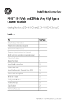
2.1.
Counter Mode
The Counter Mode reads incoming pulses and returns a binary number (0 - 16,777,215max) to the
Backplane bus. The Counter mode accepts only single phase inputs. The module will determine the
Phase B input state, and count up or down accordingly.
Channel A Input is used as the counting pulse while channel B is used to determine the direction.
[B = High, Count = Down; B = Low or floating (not connected), Count = Up]
The Channel B input may be tied high or low for unidirectional counting, or toggled for bidirectional counting.
Counter Mode
A Input
Input A
B Direction
Input B
Z (Store Count)
Input Z
(Gate / Reset )
Single Phase Pulse Generator
RIO-CU5/24
Count Up
Count Down
A Input
B Input
Count
0
1
2
3
2
6 of 51
1
0
Outputs
Updated
Continuously
Title: RIO-CU5, -RIO-CU24, -RIO-CU5L and -RIO-CU24L Counter Modules
"How to Use" Guide
2.2.
Encoder Modes
The Encoder Mode reads incoming pulses and returns a binary number (0 - 16,777,215max) to the
Backplane bus. The Encoder mode will accept only 2 phase quadrature inputs. The module will
sense the relationship between the 2 phases, and count up or down accordingly.
There are two basic encoder types, absolute and incremental. A single output incremental encoder is
called a tachometer encoder. A dual channel incremental encoder with one channel leading the other
by 90° is called a quadrature encoder.
A system using a quadrature encoder may include an optional zero pulse, or index, serving as a
reference mark for system reset. The principal disadvantage of a system using incremental encoders
is that a power interruption causes the loss of position reference, so a system must be reinitialized or
returned to a known zero position.
Absolute encoders typically have higher speed requirements (200 KHz typical) for motion control
applications. An absolute encoder has a unique code associated with each position, so the exact
position is always known, even if the system power is turned off.
7 of 51
Title: RIO-CU5, -RIO-CU24, -RIO-CU5L and -RIO-CU24L Counter Modules
"How to Use" Guide
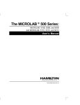
2.2.1.
Encoder Mode - X1, X2, X4 Multiplying
Encoder Mode
A
Input A
B
Input B
Z (Store Count)
Input Z
(Gate / Reset )
Quadrature Encoder
RIO-CU5/24
Forward Rotation
Reverse Rotation
A Input
B Input
1
2
3
2
1
0
X1 Count
1
2
3
4
5
6
5
9
10 11 12
11 10 9
4
3
2
8 7
6
5 4
1
0
2 1
0
X2 Count
1
2
3
4
5
6
7
8
X4 Count
3
Outputs
Updated
Continuously
X1 Multiplying Encoder Mode
Quadrature input signals are used to count on the Leading (up direction) OR Trailing (down
direction) edge of A for a bi-directional count, and channel B is used to determine the direction.
[ B = leads A, Count = Down; B = follows A, Count = Up ]
X2 Multiplying Encoder Mode
Quadrature input signals are used to count on Leading AND Trailing edges of A for a bi-directional
count, and channel B is used to determine the direction.
[ B = leads A, Count = Down; B = follows A, Count = Up ]
X4 Multiplying Encoder Mode
Quadrature input signals are used to count on Leading AND Trailing edges of A AND B for a bidirectional count, and channel B is used to determine the direction.
[ B = leads A, Count = Down; B = follows A, Count = Up ]
8 of 51
Title: RIO-CU5, -RIO-CU24, -RIO-CU5L and -RIO-CU24L Counter Modules
"How to Use" Guide
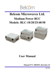
2.3.
Period / Rate Mode
The Period / Rate Mode will return an incoming frequency and a total accumulated count to the
Backplane bus, by gating an internal 5MHz internal clock with an external signal.
This mode determines the frequency and total number of input pulses by counting the number of
internal 5MHz clock pulses over a user-specified number of input signal pulses. At the end of the
specified number of pulses, the module returns the frequency (0 - 1MHz). When the frequency is
updated, both outputs are checked against their associated presets.
Period / Rate Mode
A ( Not Used )
Input A
B ( Not Used )
Input B
Z
Input Z
(Gate / Reset )
Encoder / Pulse Generator
Scalar
5 MHz Clk
RIO-CU5/24
Z Input ( Pulse )
5 MHz Internal
Sampling Clock
1
10
Accumulated Count
20
Frequency & Outputs
Updated Here
Assumes symmetrical pulse, 50% duty cycle, so Period = Sample Time On X 2 {On & Off}
Frequency = 1 / Period If Count = 20, Scalar = 1, and Clock Period = ( 1 / 5 MHz )
Frequency = 1 / [ ( 20 / 1 ) X ( 1 / 5 MHz ) X 2 ] = 125 kHz
As the frequency of the incoming pulse train at the Z (Gate / Reset) terminal increases, the number of
sampled pulses from the 5MHz clock decreases. Since accuracy is related to the number of pulses
received over the sample period, the accuracy will decrease with increasing frequencies at the Gate /
Reset terminal. Refer to the following Scaling table.
9 of 51
Title: RIO-CU5, -RIO-CU24, -RIO-CU5L and -RIO-CU24L Counter Modules
"How to Use" Guide
Relationship Between Sampled Pulses and Input Frequency
Input Frequency at
Z Gate / Reset
Terminal in Hz
2.5
5
10
20
50
100
200
500
1 kHz
2 kHz
5 kHz
10 kHz
20 kHz
50 kHz
100 kHz
Sample Pulses for
1/2 Cycle of Z
Gate / Reset Pulse
1M
500 k
250 k
125 k
50 k
25 k
12.5 k
5k
2.5 k
1.25 k
500
250
125
50
25
To some extent, scaling the input frequency through the use of a scalar can lessen the decrease in
accuracy. A scalar value of 1 will only return an accurate input frequency if incoming input pulses
have a 50% duty cycle.
Operation of Scalar
In the Period / Rate and Continuous / Rate modes, the scalar lets the incoming pulse train at the Z
Gate / Reset pin be divided by a user defined number. There is one scalar value for each counter.
Acceptable values for the scalar are 1, 2, 4, 8, 16, 32, 64, and 128. The default value for each scalar
is 1. Note that a “0” scalar is equivalent to a “1”.
The product of the Sample Period times the scalar should be less than 6.71 seconds in order to avoid
a zero frequency detect indication.
(5 MHz sample time = 200ns; 16,777,216 counts x 200ns x 2 half cycles of Z = 6.71 seconds)
10 of 51
Title: RIO-CU5, -RIO-CU24, -RIO-CU5L and -RIO-CU24L Counter Modules
"How to Use" Guide
2.4.
Continuous / Rate Mode (RIO-CU5 & RIO-CU24 only)
The Continuous / Rate Mode will return an incoming frequency and a total accumulated count to
Backplane bus, by gating an internal 5MHz internal clock with an external signal.
Similar to the Period / Rate mode except outputs in this mode are updated continuously. This mode
determines the frequency and total number of input pulses by counting the number of internal 5MHz
clock pulses over a user-specified number of input signal pulses. Each output is turned on as soon as
the turn-on count is reached, and turned off as soon as the turn-off count is reached. As the internal
5MHz clock is counted, the outputs dynamically track the 5MHz count.
Continuous / Rate Mode
A ( Not Used )
Input A
B ( Not Used )
Input B
Z
Input Z
(Gate / Reset )
Encoder / Pulse Generator
Scalar
5 MHz Clk
RIO-CU5/24
Z Input ( Pulse )
Frequency
Updated Here
5 MHz Internal
Sampling Clock
1
10
20
Accumulated Count
Outputs Updated
Continuously
Assumes symmetrical pulse, 50% duty cycle, so Period = Sample Time On X 2 {On & Off}
Frequency = 1 / Period If Count = 20, Scalar = 1, and Clock Period = ( 1 / 5 MHz )
Frequency = 1 / [ ( 20 / 1 ) X ( 1 / 5 MHz ) X 2 ] = 125 kHz
As the frequency of the incoming pulse train at the Z Gate / Reset terminal increases, the number of
sampled pulses from the 5MHz clock decreases. Since accuracy is related to the number of pulses
received over the sample period, the accuracy will decrease with increasing frequencies at the Gate /
Reset terminal.
Refer to the “Operation of Scalar” information and table in the Period / Rate Mode.
11 of 51
Title: RIO-CU5, -RIO-CU24, -RIO-CU5L and -RIO-CU24L Counter Modules
"How to Use" Guide
2.5.
Rate Measurement Mode
The Rate Measurement Mode will return an incoming frequency and a total accumulated count to
the Backplane bus, based upon a user selected sample period.
This mode determines the frequency and total number of input pulses by counting the number of
incoming pulses over a user-specified sample period. At the end of the interval, the module returns a
value representing the sampled number of pulses and a value indicating the incoming frequency.
When the count and frequency are updated, any associated outputs are checked against their
associated presets. Frequency is calculated by dividing the accumulated count by the user selected
time period, and is returned in the read data. Allowable time periods are 10 milliseconds to 3 seconds
in 10 millisecond increments, with a default value of 1 second. Note that a “0” time period is
equivalent to the 1 second default.
Rate / Measurement Mode
A Input
B ( Not Used )
Z ( Not Used )
(Gate / Reset )
Encoder / Pulse Generator
Input A
Input B
Input Z
Time Base
RIO-CU5/24
A Input ( Pulse )
Internal Sampling Gate
1
2
3
Accumulated Count
User Selectable Sample Period,
10 ms to 3 seconds in 10 ms increments.
Frequency Calculated,
Outputs Updated Here
If Sample Period is 50 ms, and Count = 3, then Frequency = 3 / 50 ms = 60 Hz
12 of 51
Title: RIO-CU5, -RIO-CU24, -RIO-CU5L and -RIO-CU24L Counter Modules
"How to Use" Guide
2.6.
PWM Mode (RIO-CU5 and RIO-CU24 only)
The Pulse Width Modulation mode uses the counter to generate a continuous rolling sequence of
numbers. The real-time PWM value written to the module is converted to a window edge so that a
variable duty cycle signal can be generated. The counter will reset to zero based upon the PWM
Period programmed into the module. Any output tied to Window 0 will transmit the PWM signal.
By specifying the PWM mode (configuration word 0), a period (configuration word 2) and a gate
interval (configuration word 3 or 4), the counter its rollover and its first On/Off compare window
(Window 0) is assigned (for internal use by the module). If an output is tied to compare window 0,
that output will have a duty cycle controlled by the PWM output value (output word 2 or 3).
Additionally, the remaining three compare windows associated with the channel (i.e. the counter),
may be programmed with On and Off values, thereby providing signals related to the PWM signal
generated by compare window 0.
When using a counter in PWM mode, its rollover is internally set to:
PWM period x 5MHz = rollover [i.e. 0 to (rollover-1)]
Example:
100ms x 5MHz = 500,000
[0 to 499,999]
where:
PWM period is the product of the time base times the gate
interval.
5MHz is the internal sample rate.
Thus, to generate additional signals from a counter set up for PWM, compare windows 1 through 3
may be programmed for On and Off values in the range of 0 to rollover-1.
2.7.
Pulse Generator Mode (RIO-CU5 and RIO-CU24 only) New for Series C
The Pulse Generator Mode uses the Z input to enable the counter. Specifying the window compare
values appropriately may then be used to generate a pulse. When the Z input is “inactive”, the
counter is cleared and held at zero. Once the Z input goes “active”, the counter begins incrementing
at a 1.25MHz rate until the Z input returns to its inactive state. If the Z input remains active greater
than 13.4 seconds, the counter will saturate at 0x00FFFFFF and remain there - providing a timeouthold function. This state can be exited by toggling the Counter Preset bit once an appropriate Preset
Value has been initialized (usually zero). It should be noted that, opposed to the other modes, the CP
bit must be explicitly set and cleared.
This mode may also be used to count the “active” duration of the Z input trigger (Present Channel
Data) and the number of triggers received (Stored Channel Data). Counts cannot be attenuated in
this mode.
The Z input invert works in this mode, so that a de-energized Z input may be recognized as “active”.
The scalar is available in this mode, which permits output pulses to be generated over multiple Z
activations.
13 of 51
Title: RIO-CU5, -RIO-CU24, -RIO-CU5L and -RIO-CU24L Counter Modules
"How to Use" Guide
2.8.
New Data Indicator
A two bit counter, C1 & C0, will be available, which will be updated every time an "event" occurs
indicating that new data is available in the Stored/Accumulated Count words. Events are defined by:
•
•
•
Any active gate transition in any of the Store Count (Counter or Encoder) modes;
The end of the gate sample period in either the Period / Rate, Continuous / Rate or Pulse
Generator modes;
The end of the programmed sample period in the Rate Measurement or PWM mode.
To use these bits reliably, acquisition of data from the Counter Module must occur faster than the
events, which cause C1/C0 to increment. When C1/C0 is updated, a Change Of State (COS)
message can be sent.
2.9.
Default Configuration
The module's default configuration will be:
VHSC:
RIO-CU5L & RIO-CU24L:
Counter Mode = 0x00
50Hz filter on A, B and Z = 0x78
Decimal Position = 0x00
Active Output Assembly is 105 = 0x00
No time base = 0x0000
No gate interval = 0x00
No scalar = 0x00
Output 0 untied = 0x00
Output 1 untied = 0x00
Rollover = 0x00FFFFFF
Preset = 0x00000000
Window comparators = 0x00000000
(all)
PWM Safe State = 0x0000
Counter Control Safe State = 0x00
Output Control Safe State = 0x00
Counter Mode = 0x00
50Hz filter on A, B and Z = 0x78
Decimal Position = 0x00
Reserved = 0x00
No time base = 0x0000
No gate interval = 0x00
No scalar = 0x00
Rollover = 0x00FFFFFF
Preset = 0x00000000
Counter Control Safe State = 0x00
14 of 51
Title: RIO-CU5, -RIO-CU24, -RIO-CU5L and -RIO-CU24L Counter Modules
"How to Use" Guide
2.10. Application of New Configurations
When a configuration is sent to the RIO-CU5/24, it is checked for consistency before being applied.
If an error is found in the configuration, the PE bit is asserted and the module locally retains its
previous configuration. To isolate any problems an improperly configured module may have, the user
application program (i.e. ladder program) should monitor this error.
If the configuration is considered acceptable, the counter ASIC is disabled (i.e. counting is suspended
and outputs are shut off), while the ASIC is loaded with the new operational parameters.
15 of 51
Title: RIO-CU5, -RIO-CU24, -RIO-CU5L and -RIO-CU24L Counter Modules
"How to Use" Guide
3.
Operating Mode Features
3.1.
Operating Mode Features
The Z Gate/Reset Terminal will operate in one of four modes when the Store Count feature is in use.
The four figures below detail the operation in each mode.
Store Count Mode 1: Store/Continue
In mode 1, the rising edge of a pulse input on the Z Gate/Reset terminal will cause the current
counter value to be read and stored in the Read Data file. The counter will continue counting. The
stored count will be available in the Stored/Accumulated Count word. The stored count information
will remain until it is overwritten with new data.
Store/Continue
Read, Store Count,
and Continue Counting
Store Count Mode 2: Store/Wait/Resume
In mode 2, the rising edge of a pulse input on the Z Gate/Reset terminal will read and store the
current counter value in the Stored/Accumulated Count word and inhibit counting while the Z
Gate/Reset terminal is high. Counting resumes on the falling edge of the pulse at the Z Gate/Reset
terminal. The stored count information will remain until it is overwritten with new data.
Store/Wait/Resume
Stop Counting
Store Count
Resume Counting
16 of 51
Title: RIO-CU5, -RIO-CU24, -RIO-CU5L and -RIO-CU24L Counter Modules
"How to Use" Guide
Store Count Mode 3: Store-Reset/Wait/Start
In mode 3, the rising edge of a pulse input on the Z Gate/Reset terminal will stop counting, read and
store the current counter value in the Stored/Accumulated Count word, and reset the counter to
zero. The counter does not count while the input pulse on the Z Gate/Reset terminal is high.
Counting resumes from zero on the falling edge of the pulse at the Gate/Reset terminal. The stored
count information will remain until it is overwritten with new data.
Store-Reset/Wait/Start
Counter has stopped Counting
Stop Count, Store,
and Reset to zero
Start Counting
from zero
Store Count Mode 4: Store-Reset/Start
In mode 4, the rising edge of a pulse input on the Z Gate/Reset terminal will store the current
counter value in the Stored/Accumulated Count word and reset the counter to zero. The counter will
continue counting while the Z Gate/Reset terminal is high. The stored count information will remain
until it is overwritten with new data.
Store-Reset/Start
Start Counting
Store Count,
and Reset to zero
Continue Counting
17 of 51
Title: RIO-CU5, -RIO-CU24, -RIO-CU5L and -RIO-CU24L Counter Modules
"How to Use" Guide
3.2.
Output Control
To connect an output to a compare window, the user could program the module accordingly:
Tie Output 0 to Window 0
Program Window 0 ON Value to 2000
Program Window 0 OFF Value to 5000
ON-OFF Operation of Output 0
Output remains energized for 3000 additional counts
Output turns ON at count value of 2000
Output turns OFF at count value of 5000
If the OFF value is greater than the ON value, the output turns ON at 2000 and OFF at 5000
(Left figure). If the ON value is greater than the OFF value, the output turns OFF at 2000 and ON
at 5000 (Right figure).
Effect of ON-OFF Value on Output
Operation
Output remains Energized
for 3000 additional counts
Output turns ON
at count of 2000
Output remains De-Energized
for 3000 additional counts
Output turns OFF Output turns OFF
at count of 5000 at count of 2000
Turn Off Value > Turn On Value
Output turns ON
at count of 5000
Turn On Value > Turn Off Value
18 of 51
Title: RIO-CU5, -RIO-CU24, -RIO-CU5L and -RIO-CU24L Counter Modules
"How to Use" Guide
4.
Product Specifications
4.1.
I/O Interface Specifications
4.1.1.
5 / 15-24 VDC Input Point Features / Considerations
The input circuitry of RIO-CU5 and RIO-CU5L modules will be compatible with a 5Vdc differential
line driver, single ended driver, open collector circuit and electromechanical switches. The input
circuitry of RIO-CU24 and RIO-CU24L modules will be compatible with a 15-24Vdc differential
line driver, single ended driver, open collector circuit and electromechanical switches.
To turn on an input circuit, the user must source current through the input resistors sufficient to turn
on the opto-isolator in the circuit.
If no connection is made to a pair of input terminals, no current will flow through the photodiode of
the opto-isolator and that channel will be off. Its corresponding input status indicator will be off.
All 3 Inputs are electrically identical (A, B, Z) and consist of the following:
Channel A and A return, Channel B and B return, Gate Z and Z return
There are 2 basic classes of driver devices built into encoders and other pulse sources: single-ended
and differential. A single-ended driver output consists of a signal and a ground reference. A
differential driver consists of a pair of totem-pole outputs driven out of phase. One terminal actively
sources current while the other sinks, and there is no direct connection to ground.
Differential line drivers provide reliable, high-speed communication over long wires. Most
differential line drivers are powered by 5V, and are more immune to noise than single-ended drivers
at any operating voltage.
4.1.2.
Lead Breakage / Missing Pulse / Zero Frequency Considerations
First, a few definitions are needed to define the intended operation of the Counter Modules:
Lead Breakage
Typically requires a shunt resistor (across the load) to detect 3 levels of current / input states - Open
(Wire Off, Device = ?), Off (Wire OK, Device Off), On (Wire OK, Device On). This method does
not check the input against a time base, only that the device wiring (current loop) is intact.
Missing Pulse
Typically uses an input pulse to reset a watchdog timer (fixed or programmable HW).
This method does detect “Lead Breakage”, since a broken wire will time-out the watchdog.
19 of 51
Title: RIO-CU5, -RIO-CU24, -RIO-CU5L and -RIO-CU24L Counter Modules
"How to Use" Guide
Zero Frequency
Typically uses an input pulse to calculate an input frequency and verify it is above an error threshold.
This method does detect “Lead Breakage”, since a broken wire will generate a 0 Hz. frequency.
“Missing Pulse” or “Zero Frequency” will also detect a customer device stuck “high’ or “low”, since
the counter is monitoring for a change in the input state. Currently, the Counter / Encoder Modes do
not have Zero Frequency Detection - the “A” & “B” inputs are time independent, only looking for
input edge changes to increment / decrement the count value.
The Period / Rate and Continuous Rate modes do have Zero Frequency Detection, since the “Z”
input is monitored for Zero Frequency in Firmware (A and B inputs not used, and not monitored).
The Rate Measurement mode inherently has Zero Frequency Detection, since no “A” pulses in any
sample period are = 0 Hz (B and Z inputs not used, and not monitored).
Operational Mode
Counter
Encoder
Period / Rate
Continuous / Rate
Rate Measurement
PWM
Pulse Generator
Zero
Frequency
Detection
N
N
Y
Y
Y
N
N
20 of 51
Input
Monitored
None
None
Z Only
Z Only
A Only
None
Z only
Title: RIO-CU5, -RIO-CU24, -RIO-CU5L and -RIO-CU24L Counter Modules
"How to Use" Guide
4.1.3.
Input Specifications
Number of Counters
1
Maximum Count Value
16,777,215 (24 bit counter)
Number of Inputs
1 group of A/Areturn, B/Breturn and Z/Zreturn.
Input Voltage
5Vdc (RIO-CU5 & RIO-CU5L) or 15-24Vdc (RIO-CU24 & RIOCU24L)
Input Current
19.1mA @ 5Vdc, 25.7mA @ 6Vdc (RIO-CU5 & RIO-CU5L),
6.1mA @ 15Vdc, 10.2mA @ 24Vdc (RIO-CU24 & RIO-CU24L)
Input Off-State Current
≤ 0.250mA
Input Off-State Voltage
≤ 1.25Vdc (RIO-CU5 & RIO-CU5L), ≤ 1.8Vdc (RIO-CU24 &
RIO-CU24L)
Input On-State Current
≥ 5mA
Input On-State Voltage
≥ 2.6Vdc (RIO-CU5 & RIO-CU5L), ≥ 12.5Vdc (RIO-CU24 &
RIO-CU24L)
Maximum On-State Voltage1
± 6V (RIO-CU5 & RIO-CU5L),
See derating figure below (RIO-CU24 & RIO-CU24L).
Input Filter Selections
5 selections: OFF or 10µs/100µs/1.0ms/10.0ms per A/B/Z group.
See text for details.
Maximum Input Frequency
1.0MHz counter and encoder x1configurations (no filters),
500kHz encoder x2 configuration (no filters),
250kHz encoder x4 configuration (no filters).
21 of 51
Title: RIO-CU5, -RIO-CU24, -RIO-CU5L and -RIO-CU24L Counter Modules
"How to Use" Guide
4.1.4.
Output Specifications (This section only applies to RIO-CU5 & RIO-CU24)
Number of Outputs
1 isolated group of 2 capable of 0.5A max. @ 24Vdc.
Output Control
Outputs may be tied to any of 4 compare windows.
Output-Supply Voltage Range
10-28.8Vdc
Off-State Leakage Current
≤ 0.5mA
On-State Voltage Drop
≤ 0.3Vdc @ 0.5A.
On-State Current Maximum
0.5A
Max Module Output Current
1.0A
Short Circuit Current
~6A Outputs are short circuit protected and, based upon
programming, either cycle until the fault is corrected or latch off.
Short circuit detected when output is turned ON.
Open Wire Detection
Open wire detected when output is turned OFF.
Delay Time, Off /On
25µs (load dependent)
Delay Time, On/Off
150µs (load dependent)
1
Exceeding the maximum input voltage may cause permanent damage to the input.
22 of 51
Title: RIO-CU5, -RIO-CU24, -RIO-CU5L and -RIO-CU24L Counter Modules
"How to Use" Guide
4.1.5.
General Specifications
Terminal Base Compatibility
RIO-BSC/BSP or RIO-BSC3/BSP3
Terminations
A (M1-0), Aret (M1-1),
B (M1-2), Bret (M1-3),
Z, (M1-4), Zret, (M1-5),
Out 0/ChasGnd(opt) (M1-6), Out 1/ChasGnd(opt) (M1-7),
ChasGnd (M2-0), ChasGnd (M2-1),
Out 0 Return (M2-2), Out1 Return (M2-3),
Vaux− (M2-4), Vaux− (M2-5),
Vaux+ (M2-6), Vaux+ (M2-7)
Backplane bus Current
160mA (RIO-CU5L and RIO-CU24L), 180 mA (RIO-CU5 and
RIO-CU24)
Power Dissipation
1.5W (RIO-CU5), 1.9W (RIO-CU24), 1.1W (RIO-CU5L), 1.5 W
(RIO-CU24L),
Keyswitch Position
2
Indicators
3 Input status system side yellow LEDs;
2 Output status system side red/yellow LEDs;
1 Network status system side red/green LEDs;
1 Module status system side red/green LEDs.
Isolation Voltage
Modules are pre-qualified for 1250Vacrms between each of the
four isolated areas:
Module 1:
a) System side (Backplane bus),
b) A/B/Z inputs,
c) O0/O1 and user power supply,
d) Chassis Ground.
Module 2:
a)
b)
c)
d)
System side (Backplane bus),
Chassis Ground,
Vaux +/-,
User power supply common.
External DC Power2
No additional external power is needed to power the module.
Field Power Bus
24Vdc nominal; range 10-28.8Vdc
Dimensions
2.97”L x 0.472”W x 2.21”H or 75.5mm x 12mm x 56mm
2
Does not represent power required to supply the outputs.
23 of 51
Title: RIO-CU5, -RIO-CU24, -RIO-CU5L and -RIO-CU24L Counter Modules
"How to Use" Guide
Environmental Conditions
Operational Temperature
Storage Temperature
Relative Humidity
Shock Operating
Non-operating
Vibration
Conductors Wire Size
Category
4.2.
4.2.1.
-20 to 55°C (-4 to 131°F)
-40 to 85°C (-40 to 185°F)
5 to 95% non-condensing (operating)
5 to 80% non-condensing (non-operating)
30g peak acceleration, 11(±1)ms pulse width
50g peak acceleration, 11(±1)ms pulse width
Tested 5g @ 10-500Hz per IEC 68-2-6
14 gauge stranded maximum
3/64 inch (1.2mm) insulation maximum
2
Pin and Wiring Assignments
High Speed Counter Module-to-Terminal Base Connector
The Counter Modules plug into a terminal base via a 20 position edge card connector, which enables
the module to make connections to screw or spring clip terminals for customer field device I/O and
power. In addition, Backplane bus signals also make connections through this interface. A signal
description follows:
Module 1 (M1)
Pin Number
1
2
3
4
5
6
7
8
9
10
11
12
13
14
15
16
17
18
19
20
Module 2 (M2)
Description
Pin Number
Screw 0 - A
1
Screw 1 - Aret
2
Screw 2 - B
3
Screw 3 - Bret
4
Screw 4 - Z
5
Screw 5 - Zret
6
Screw 6 - Output 0 / Ground (-CU5L,-CU24L) 7
Screw 7 - Output 1 / Ground (-CU5L,-CU24L) 8
Chassis Ground
9
Chassis Ground
10
User_Supply (for outputs)
11
User_Supply (for outputs)
12
Common
13
Common
14
Bus_Can_H
15
Ground
16
Bus_Can_L
17
Vcc
18
Bus_Ena_In_L
19
Bus_Ena_Out_L
20
24 of 51
Description
Screw 0 - Chassis Ground (for shield)
Screw 1 - Chassis Ground (for shield)
Screw 2 - Common (output return)
Screw 3 - Common (output return)
Screw 4 - Vaux− (for encoder)
Screw 5 - Vaux− (for encoder)
Screw 6 - Vaux+ (for encoder)
Screw 7 - Vaux+ (for encoder)
Chassis Ground
Chassis Ground
No Connect
No Connect
Common
Common
No Connect
No Connect
No Connect
No Connect
Bus_En pass-thru
Bus_En pass-thru
Title: RIO-CU5, -RIO-CU24, -RIO-CU5L and -RIO-CU24L Counter Modules
"How to Use" Guide
4.2.2.
Terminal Base Field Wiring Assignments
The proposed terminal assignments for customer connections to the EH-RIO Terminal Base are
shown below. To meet European standards, the terminal base assignments provide one location for
every wire.
RIO-CU5/24 Terminal Wiring
Terminal Wiring
4.3.
RIO-CU5L/-RIO-CU24L
Input/Output/Information/Configuration Data
The Counter Modules require several words to communicate real time input and output data as well
as non-real time module information (i.e. description, revision, etc) and configuration. The following
tables show the words, which must be exchanged.
Data may be read or written (get or set service) using an Explicit Message. For example, to read the
Present Channel Data, Assembly 6516 (10110) can be requested:
Service
0E (get)
Class
04 (assembly)
Data is ordered accordingly:
where: byte0 is the LSB
4.3.1
Instance
65 (Present Data)
8 bit byte
16 bit word
32 bit long word
RIO-CU5 & RIO-CU24 Assemblies
Class Code: 04
Class Attributes
None
Class Services
None
Instance Attributes
3
Data Get/Set
Instance Services
0x0E Get Attribute Single
0x10 Set Attribute Single
25 of 51
Attribute
03 (Data Attribute)
byte0
byte0, byte1
byte0, byte1, byte2, byte3
Title: RIO-CU5, -RIO-CU24, -RIO-CU5L and -RIO-CU24L Counter Modules
"How to Use" Guide
Instantiated Instances
INSTANCE
#101 (0x65)
Services
Get
#102 (0x66)
Get
#103 (0x67)
Get
#104 (0x68)
#105 (0x69)
Get
Set/Get
#106 (0x6a)
#107 (0x6b)
Set/Get
Set/Get
#108 (0x6c)
Set/Get
FIELD
Present Channel Data
Status
Stored Channel Data
Status
Present Channel Data
Stored Channel Data
Status
Programming Error Code
Counter Control
Output Control
PWM Value
PWM Value
Counter Control
Output Control
Counter Configuration
Filter Selection
Decimal Position
Active Output Assembly
Time Base or PWM Period
Gate Interval
Scalar
Output 0 Ties
Output 1 Ties
Rollover Value
Preset Value
ON Value # 1
OFF Value #1
ON Value # 2
OFF Value #2
ON Value # 3
OFF Value #3
ON Value # 4
OFF Value #4
PWM Safe State Value
Counter Control SSV
Output Control SSV
BYTES
4
2
4
2
4
4
2
2
1
1
2
2
1
1
1
1
1
1
2
1
1
1
1
4
4
4
4
4
4
4
4
4
4
2
1
1
Assembly 101 is produced for a polled connection, Assembly 102 is produced for a COS connection,
Assembly 103, 104, 107 and 108 are by Explicit message only and Assembly 105 & 106 are
consumed in a polled connection (as directed by Parameter 4).
26 of 51
Title: RIO-CU5, -RIO-CU24, -RIO-CU5L and -RIO-CU24L Counter Modules
"How to Use" Guide
INSTANCE
#123 (0x7b)
Services
Set/Get
FIELD
Counter Configuration
Filter Selection
Decimal Position
Reserved (set to 0)
Time Base or PWM Period
Gate Interval
Scalar
Output 0 Ties
Output 1 Ties
Alignment (reserved = 0)
Rollover Value
Preset Value
ON Value # 1
OFF Value #1
ON Value # 2
OFF Value #2
ON Value # 3
OFF Value #3
ON Value # 4
OFF Value #4
PWM Safe State Value
Counter Control SSV
Output Control SSV
BYTES
1
1
1
1
2
1
1
1
1
2
4
4
4
4
4
4
4
4
4
4
2
1
1
Note: Assembly 123 was added at firmware revision 3.001. It was needed to provide long word
alignment.
27 of 51
Title: RIO-CU5, -RIO-CU24, -RIO-CU5L and -RIO-CU24L Counter Modules
"How to Use" Guide
4.3.2
RIO-CU5/24 Parameter Classes
Class Code: 0F
Class Attributes
None
Class Services
None
Instance Attributes
1
Data Get/Set
Instance Services
0x0E Get Attribute Single
0x10 Set Attribute Single
Parameter #
1
2
3
4
5
6
7
8
9
10
11
12
13
14
15
16
17
18
19
20
21
22
23
24
25
Set/Get
"
"
"
"
"
"
"
"
"
"
"
"
"
"
"
"
"
"
"
"
"
"
"
"
Counter Configuration
Filter Selection
Decimal Position
Active Output Assembly
Time Base or PWM Period
Gate Interval
Scalar
Output 0 Ties
Output 1 Ties
Rollover Value
Preset Value
ON Value # 1
OFF Value #1
ON Value # 2
OFF Value #2
ON Value # 3
OFF Value #3
ON Value # 4
OFF Value #4
PWM Safe State Value
Counter Control SSV
Output Control SSV
Requested Poll Produce Assy
Requested COS Produce Assy
Requested Poll Consume Assy
Note: Parameters 23, 24 & 25 are new for Series C - firmware revision 3.001.
28 of 51
1
1
1
1
2
1
1
1
1
4
4
4
4
4
4
4
4
4
4
2
1
1
1
1
1
Title: RIO-CU5, -RIO-CU24, -RIO-CU5L and -RIO-CU24L Counter Modules
"How to Use" Guide
4.3.3
RIO-CU5L & RIO-CU24L Assemblies
Class Code: 04
Class Attributes
None
Class Services
None
Instance Attributes
3
Data Get/Set
Instance Services
0x0E Get Attribute Single
0x10 Set Attribute Single
Instantiated Instances
INSTANCE
#101 (0x65)
Services
Get
#102 (0x66)
Get
#103 (0x67)
Get
#104 (0x68)
#105 (0x69)
#106 (0x6a)
Get
Set/Get
Set/Get
#123 (0x7b)
Set/Get
29 of 51
FIELD
Present Channel Data
Status
Stored Channel Data
Status
Present Channel Data
Stored Channel Data
Status
Programming Error Code
Counter Control
Counter Configuration
Filter Selection
Decimal Position
Reserved
Time Base
Gate Interval
Scalar
Rollover Value
Preset Value
Counter Control SSV
Counter Configuration
Filter Selection
Decimal Position
Reserved
Time Base
Gate Interval
Scalar
Rollover Value
Preset Value
BYTES
4
2
4
2
4
4
2
2
1
1
1
1
1
2
1
1
4
4
1
1
1
1
1
2
1
1
4
4
Title: RIO-CU5, -RIO-CU24, -RIO-CU5L and -RIO-CU24L Counter Modules
"How to Use" Guide
Counter Control SSV
Alignment (reserved = 0)
1
1
Assembly 101 is produced for a polled connection, Assembly 102 is produced for a COS connection,
Assembly 103, 104 and 106 are by Explicit message only and Assembly 105 is consumed in a polled
connection.
Note: Assembly 123 was added at firmware revision 3.001.
30 of 51
Title: RIO-CU5, -RIO-CU24, -RIO-CU5L and -RIO-CU24L Counter Modules
"How to Use" Guide
4.3.4
RIO-CU5L/RIO-CU24L Parameter Classes
Class Code: 0F
Class Attributes
None
Class Services
None
Instance Attributes
1
Data Get/Set
Instance Services
0x0E Get Attribute Single
0x10 Set Attribute Single
Parameter #
1
2
3
4
5
6
7
8
9
10
11
12
Set/Get
"
"
"
"
"
"
"
"
"
"
"
Counter Configuration
Filter Selection
Decimal Position
Reserved
Time Base
Gate Interval
Scalar
Rollover Value
Preset Value
Counter Control SSV
Requested Poll Produce Assy
Requested COS Produce Assy
Note: Parameters 11 & 12 are new for Series C - firmware revision 3.001.
31 of 51
1
1
1
1
2
1
1
4
4
1
1
1
Title: RIO-CU5, -RIO-CU24, -RIO-CU5L and -RIO-CU24L Counter Modules
"How to Use" Guide
4.3.5
Format of the Data
Input Information
Present Channel Data
Stored Channel Data
Status
Programming Error Code
32 bit value of the present counter state
32 bit value of the stored/accumulated count
PE EF NR 0 FS FS OS OS 0 ZS BS AS C1 C0 ZD 0
PE 0 0 0 0 E10 E9 E8 E7 E6 E5 E4 E3 E2 E1 E0
Output Information
Counter Control
Output Control
PWM Value
0 0 0 0 0 VR CP CR
DS ES OE FO DS ES OE FO
16 bit decimal value with range from 0-9500 (0-95.00%)
Configuration Information
Counter Configuration
ZI MD MD MD CF CF CF CF
Filter Selection
0 ZF BF AF FS FS FS FS
Decimal Position
8 bit value used to modify the Present Channel Data display
Active Output Assembly
Assembly # (0, 105 or 106)
Time Base or PWM Period
16 bit value used to set the time base or PWM period
Gate Interval
8 bit value used to set the gate interval
Scalar
8 bit value used to divide the Z input by 2n
Output 0 Ties
0 0 0 0 T3 T2 T1 T0
Output 1 Ties
0 0 0 0 T3 T2 T1 T0
Rollover Value
32 bit value at which the counter is commanded to rollover
Preset Value
32 bit value the counter is to be set when CP is asserted
ON Value # 1
\
OFF Value # 1
\
ON Value # 2
\
OFF Value # 2
\ 32 bit values that set the 4 compare windows
ON Value # 3
/
OFF Value # 3
/
ON Value # 4
/
OFF Value # 4
/
PWM Safe State Value
16 bit safe state value for the PWM signal
Counter Control Safe State Value
0 0 0 0 0 VR CP CR
Output Control Safe State Value
DS ES OE FO DS ES OE FO
Requested Poll Produce Assy
102, 103
Requested COS Produce Assy
Requested Poll Consume Assy
4.3.6
VHSCx - 101, 102 or 103; RIO-CU5L/RIO-CU24L - 101,
VHSCx - 102 or 103; RIO-CU5L/RIO-CU24L - 102, 103
VHSCx - 0, 105 or 106
ASA Information
Vendor ID = 1 (AB)
RIO-CU5 Product Code = 13
RIO-CU5L Product Code = 15
Product Type = 109
RIO-CU24 Product Code = 14
RIO-CU24L Product Code = 16
32 of 51
Title: RIO-CU5, -RIO-CU24, -RIO-CU5L and -RIO-CU24L Counter Modules
"How to Use" Guide
4.3.7.
Input Data
Present Channel Data
This is a 32 bit unsigned long word value representing the current count of the 24 bit counter
(configurations: count [0], x1 encoder [1], x2 encoder [2], PWM [3], x4 encoder [4], pulse
generator [8]) or the frequency (configurations: period/rate [5], continuous/rate [6], rate
measurement [7]). The range of values is 0 ≤ value ≤ 0x00FFFFFF (16,777,215).
Stored/Accumulated Channel Data
This is a 32 bit unsigned long word value representing the stored count of the counter at the
time of some specified event. In counter configurations (configurations: count [0], x1
encoder [1], x2 encoder [2], x4 encoder [4]) without store modes selected, these words are
not updated. With store modes selected, they are the stored value of the counter at the time
of the specified event (ex: rising edge of Z input). In PWM [3] configuration it is the counter
value at the end of the period specified by the product of the time base x gate interval. In
period/rate [5], continuous/rate [6] and pulse generator [8] configurations it is the total
accumulation of unscaled Z pulses (i.e. if scaling is set to 128, after 128 Z pulses the
accumulator will increase by 128 counts). The maximum frequency that accumulation can
follow in these modes is 200Hz x scalar value (ex: 200Hz x 128 is 25kHz). Finally, in rate
measurement [7] configuration, it is the total number of pulses seen at the A input
accumulated over each period as specified by the product of the time base x gate interval.
The range of values occupy the entire 32 bit size from 0 ≤ value ≤ 0xFFFFFFFF
(4,294,967,295). Changing the configuration does not clear these words.
Module/Channel Status
PE
Programming Error bit. If an incomplete, incorrect or conflicting set of configuration
parameters are sent to the module, the PE bit will be asserted and an error code will be
placed in the Programming Error Code word (assembly 6816). The module will not enter a
normal operational state. Bit definitions for the error code are:
E10: An invalid assembly was chosen for poll consumption (0, 105 or 106 are valid).
E9: The decimal point position is outside of acceptable range.
E8: Counter 0 window ON & OFF values are equal and not zero OR
Counter 0 window ON or OFF value greater than the Rollover.
E7: A tie has been connected to an unprogrammed window.
E6: A configuration was selected that requires the scalar and none was programmed
OR Multiple scalars were selected.
E5: The preset is out of range ( ≥ Rollover).
E4: A rollover of zero was programmed though PWM was not selected OR
A rollover was programmed and PWM was selected OR
Rollover is out of range ( > 0x01000000).
E3: A configuration requiring time base was selected and no gate interval was set OR
Gate interval is out of range ( > 200) OR
Product of time base and gate interval is greater than 3 seconds.
E2: A time base was entered that is not a multiple of 10 OR
Time base is out of range ( > 3000, i.e. 3 seconds).
E1: ZF/BF/AF were selected and no filter was programmed OR
33 of 51
Title: RIO-CU5, -RIO-CU24, -RIO-CU5L and -RIO-CU24L Counter Modules
"How to Use" Guide
E0:
Multiple filters were selected.
A reserved configuration/mode was programmed.
EF
EEPROM Fault status bit. If a fault is detected with the EEPROM during power up tests,
this bit is asserted to 1. It indicates that the content of the EEPROM has been corrupted,
most likely caused by loss of power during an executing write.
NR
Not Ready status bit. Whenever power is applied to the module, the hardware must be
initialized. During this time, the NR bit will be asserted.
FS
Output Fault Status indicators, where bit 11 is output 1 and bit 10 is output 0. A 1 indicates
the output is either shorted or open.
OS
Output Status indicators, where bit 9 is output 1 and bit 8 is output 0. A 1 indicates the
output is ON, 0 it is OFF.
ZS
Z input Status. This bit indicates the present status of the Z input. A 1 indicates Z is ON, a
zero, that it is OFF. This bit is unaffected by Z Invert, ZI, in the Counter Configuration word.
BS
B input Status. This bit indicates the present status of the B input. A 1 indicates B is ON, a
zero, that it is OFF.
AS
A input Status. This bit indicates the present status of the A input. A 1 indicates A is ON, a
zero, that it is OFF.
C[1,0] Stored data count. This count cycles through [ 0 0 ], [ 0 1 ], [ 1 0 ], [ 1 1 ], [ 0 0 ]…
… Each
time the stored/accumulated count words are updated, C[1,0] is incremented. This feature
assumes the host’s sample rate (including network delay and program scan) is as fast or faster
than the frequency of the event which updates C[1,0].
ZD
Zero frequency Detected. This bit becomes operational when frequency configurations are
programmed (configurations: period/rate [5], continuous/rate [6], rate measurement [7]).
In period/rate [5] and continuous/rate [6] configurations, counts are acquired during the ON
state of the Z input. At very low frequencies the counter saturates, indicating a zero
frequency detect. The time it takes to determine a zero frequency in these two configurations
can be as long as 6.7 seconds ( 16,777,216 counts x 1/5MHz x 2 half cycles of Z ). In rate
measurement [7] configuration pulses on the A input are counted over a sample interval
specified by the time base. The time it takes to determine a zero frequency in this
configuration will be determined by the sample interval (ex: time base = 0.300 second ∴ 300
milliseconds to determine ZF).
34 of 51
Title: RIO-CU5, -RIO-CU24, -RIO-CU5L and -RIO-CU24L Counter Modules
"How to Use" Guide
4.3.8.
Output Data
Counter Control
VR
Value Reset of stored/accumulated count. The transition of this bit from a 0
stored/accumulated count word. The module will return this bit to zero.
CP
Counter Preset. The transition of this bit from a 0 ⇒ 1 sets the counter to the value specified
by the Preset words. The module will return this bit to zero. Outputs are adjusted according
to the window compare values. In configuration pulse generator [8], this bit must be
returned to zero explicitly, 0 ⇒ 1 ⇒ 0, the module does not clear it.
CR
Counter Reset. The transition of this bit from a 0 ⇒ 1 clears the counter. The module will
return this bit to zero. Outputs are adjusted according to the window compare values.
⇒
1 clears the
Output Control (RIO-CU5 and RIO-CU24 only)
DS
Diagnostic Speed. When this bit is set to 1, the short circuit and open wire diagnostics will be
filtered (50ms) to prevent nuisance trips caused by noisy environments. When this bit is a
zero, diagnostics will respond in under 8ms to a fault condition.
ES
Electronic-fuse Select. When this bit is set to 1, outputs will be disabled upon the detection of
a fault (short circuit or open wire) and the output fault status indicator, FS, will be latched.
Recovery from a faulted state is achieved by sending ES=0 and OE=1 for the afflicted output.
When ES equals zero, a faulted output will continue to operate as instructed until the fault is
removed. In either case, FS is asserted to indicate a fault.
OE
Output Enable. When this bit is set to 1, outputs are permitted to turn on from either a force
on, FO, a compare match or as directed by the PWM settings. When OE equals zero, the
module turns the associated output OFF. Bit 5 & 1 represent outputs 1 & 0 respectively.
FO
Force Output. When this bit is set to 1, outputs are turned on if OE is 1. When FO equals
zero, outputs may then be controlled by a compare match or as directed by the PWM
settings. Bit 4 & 0 represent outputs 1 & 0 respectively.
PWM Value (RIO-CU5 and RIO-CU24 only)
When the module is programmed for a PWM [3] configuration, the time base is enabled, the
counter for the respective channel, its rollover AND its 1st ON and 1st OFF value are utilized.
Ties may be used to direct the PWM signal to any or both outputs. The range of PWM values
is 0 ≤ value ≤ 9500 decimal (i.e. 0.00% ≤ value ≤ 95.00%). Entering a value “below” 0 will
result in a PWM of 0%; a value greater than 9500 will result in a PWM of 95.00%. The
actual duty cycle observed at the output will depend on the turn on and turn off times of the
MOSFET, the energy storage capability of the cable/load and the resistance from output to
return.
35 of 51
Title: RIO-CU5, -RIO-CU24, -RIO-CU5L and -RIO-CU24L Counter Modules
"How to Use" Guide
Counter to Output Logical Connectivity
36 of 51
Title: RIO-CU5, -RIO-CU24, -RIO-CU5L and -RIO-CU24L Counter Modules
"How to Use" Guide
4.3.9.
Configuration Data
Counter Configuration
This byte sets the counter configuration.
7
ZI
5
4
3
2
1
0 ⇐ COUNTER 0
MD ->| |<--- CF --->|
6
|<-
0
0
0
0
0
0
0
0
0
0
0
1
1
1
0
0
1
1
0
0
1
0
1
0
1
0
1
0
counter
encoder x1
encoder x2
pwm (RIO-CU5 and RIO-CU24 only)
encoder x4
period/rate *
continuous/rate * (RIO-CU5 and RIO-CU24
0
1
1
0
1
0
1
0
rate measurement
pulse generator
store count disabled
mode 1 - store/continue
mode 2 - store/wait/resume
mode 3 - store,reset/wait/start
mode 4 - store,reset/start
reserved
reserved
reserved
Z input is not inverted
Z input is inverted
only)
0
0
0
0
1
1
1
1
0
0
1
1
0
0
1
1
0
1
0
1
0
1
0
1
0
1
Filter Selection
This byte sets the A/B/Z input filters.
7
0
6
ZF
5
BF
4
AF
3
2
1
0 ⇐ COUNTER 0
|<--- FS --->|
0
0
0
0
1
0
1
0
1
0
1
0
0
0
1
0
0
0
1
0
0
0
1
0
0
0
no filter
50kHz** (10µs +0µs / −1.6µs)
5kHz** (100µs +0µs / −13.2µs)
500Hz** (1.0ms +0µs / −125µs)
50Hz** (10.0ms +0ms / −1.25ms)
A input not filtered
apply filter to A input
B input not filtered
apply filter to B input
Z input not filtered
apply filter to Z input
* See section Real Time Input Data, Stored/Accumulated Count and Configuration Data, Scalar.
** Assumes 50% duty cycle.
37 of 51
Title: RIO-CU5, -RIO-CU24, -RIO-CU5L and -RIO-CU24L Counter Modules
"How to Use" Guide
Decimal Position
This byte changes the significant digits of the frequency or counter display.
In the frequency modes (period/rate [5], continuous/rate [6], rate measurement [7]) for
example, a -2 will move the decimal point left 2 places, dividing the frequency value by 100, a
+1 moves it right, multiplying by 10. The firmware checks for placement to be in the range -4
≤ value ≤ +2. A value outside the range will move the decimal point to the zero position and
assert the programming error (PE) bit. Moving the decimal point to the left (i.e. negative),
allows high frequencies, commonly present in rate measurement mode, to fit within a single
16 bit word. Moving the decimal point to the right (i.e. positive), allows low frequencies,
commonly present in period and continuous rate modes, to have resolution displayed to
0.1Hz and 0.01Hz. Frequencies should be kept below 3.2kHz for 0.1Hz resolution and below
320Hz for 0.01Hz. Scalars of Z/128, Z/64, Z/32 and Z/16 should not be used when decimal
positioning is applied. 0 is the default setting.
In the counter modes (counter [0], x1 encoder [1], x2 encoder [2], pwm [3], x4 encoder
[4]), it attenuates the counter display, for example, 20 divides count+1 by 20. The value may
be in the range 0 < value ≤ 255. The result of requesting a number other than 1 performs the
function: (COUNT + 1) / ATTENUATION. This is useful for scaling a large counter value to
a smaller 16 bit value or a percentage. 1 is the default setting and zero reverts to 1 to prevent
a divide by zero.
This feature has no effect in pulse generator [8] configuration.
Active Output Assembly (RIO-CU5 and RIO-CU24 only)
This byte permits selection of either assembly 105 (0x69 - Counter/Output Control) or 106
(0x6A - PWM Value) for poll consumption. Entering a zero will cause the default assembly,
105, to be selected. This is available on the RIO-CU5/24s only. For Series C and later,
Parameter 25 must be zero to access this legacy operation.
Time Base/PWM Period
This word sets the fundamental time base for the counter. Its resolution is in milliseconds
with minimum 10ms intervals (i.e. an interval of 10 milliseconds is a value of 10, 1 second is
1000). The maximum value that may be programmed is 3 seconds (3000). The time base
must be entered when the PWM [3] and rate measurement [7] configurations are used.
Gate Interval
This byte sets the counter’s gate interval using the time base setting as its time unit. (i.e. its
resolution is determined by the time base). The actual gate interval is the product of the time
base and the gate interval (ex: 50ms gate interval may be produced with a time base of 10 and
a gate interval of 5 or a time base of 50 and a gate interval of 1). The maximum value of the
product of time base x gate interval is 3 seconds. The gate interval must be entered when the
PWM [3] and rate measurement [7] configurations are used. The maximum value is 200.
38 of 51
Title: RIO-CU5, -RIO-CU24, -RIO-CU5L and -RIO-CU24L Counter Modules
"How to Use" Guide
Scalar
This byte scales the Z signal in the period/rate [5], continuous/rate [6] and pulse generator
[8] configurations. If the filter is applied, then the filtered Z is scaled. Only one bit of the
scalar should be set. Selecting a scalar will cause accumulated counts to be adjusted
accordingly (i.e. selecting a scalar of 128 will increase the accumulated count by 128 after
128 Z pulses have been received). It is highly recommended that anytime Z is scaled
(divide by 2, 4, 8, etc), the Z input should be filtered, otherwise, noise could cause
erroneous frequency readings.
7
6
5
4
3
2
1
0
|
|
|
|
|
|
|
|
|
|
|
|
|
|
|
Z Fmin = 0.149Hz
|
|
|
|
|
|
Z/2 Fmin = 0.298Hz
|
|
|
|
|
Z/4 Fmin = 0.596Hz
|
|
|
|
Z/8 Fmin = 1.192Hz
|
|
|
Z/16 Fmin = 2.384Hz
|
|
Z/32 Fmin = 4.768Hz
|
Z/64 Fmin = 9.537Hz
Z/128 Fmin = 19.073Hz
Fmin indicates the frequency at which the 24bit counter overflows.
Output 0-1 Ties (RIO-CU5 and RIO-CU24 only)
The bits in these two bytes connect the specified output to the appropriate compare window.
There are four windows associated with the counter. Each output may be connected to any
number of windows, from one to all four. The bits are defined as follows:
T0
T1
T2
T3
Tie Output to 1st Compare Window (also the PWM signal in PWM [3] configuration)
Tie Output to 2nd Compare Window
Tie Output to 3rd Compare Window
Tie Output to 4th Compare Window
Rollover
This long word sets the number of counts the counter will accumulate before rolling over.
For example, a value of 1000 will produce a count sequence of: 998, 999, 0, 1, 2…
… while
incrementing or 2, 1, 0, 999, 998…
… while decrementing. Rollover is a 32 bit number with a
useable range of 1 ≤ value ≤ 0x01000000 (16,777,216). In PWM [3] configuration, this value
should be zero; in count [0], x1 encoder [1], x2 encoder [2] and x4 encoder [4]
configurations, it should be specified to some non-zero value; and in period/rate [5],
continuous/rate [6], rate measurement [7] and pulse generator [8] configurations is a ‘don’t
care’.
39 of 51
Title: RIO-CU5, -RIO-CU24, -RIO-CU5L and -RIO-CU24L Counter Modules
"How to Use" Guide
Preset
This long word sets the preset value the counter will be loaded with, when a Counter Preset,
CP, command is issued. Preset is a 32 bit number with a range of 0 ≤ value ≤ Rollover
(16,777,215max).
Counter ON and OFF Windows (RIO-CU5 and RIO-CU24 only)
These long words program the four compare window's ON and OFF values. The first
compare window for each counter is utilized in PWM [3] configuration and, when PWM is
programmed for a channel, the associated compare window should remain at 0. The range of
each entry in configuration count [0], x1 encoder [1], x2 encoder [2], x4 encoder [4] is 0 ≤
value < Rollover. The range of each entry in configurations: PWM [3], period/rate [5],
continuous/rate [6], rate measurement [7] is 0 ≤ value ≤ 0x00FFFFFF. The maximum value
is 0x00FFFFFF (16,777,215). When a tie is connected to a window comparator, that window
must be specified (i.e. ON value ≠ OFF value ≠ 0). These Windows are always interpreted as
counts, regardless of the configuration setting and may be computed as follows:
counts = ( scalar x 2.5E6 ) / desired_freq
period/rate [5], continuous/rate [6]
counts = time_base [sec] x gate_interval x desired_freq
rate measurement [7]
Safe State Values
When either the host transitions to PROGRAM mode or a communication fault (i.e. broken
network cable) occurs, the module copies these safe state words into its real-time working
buffer. The definitions are identical to those described under Real-time Output Data with the
following exception: entering a PWM Safe State value outside of the range, 0-9500, will
result in a Hold Last State to be executed.
40 of 51
Title: RIO-CU5, -RIO-CU24, -RIO-CU5L and -RIO-CU24L Counter Modules
"How to Use" Guide
4.4.
Status / Diagnostic LEDs
The Counter Modules have several system side LEDs, which behave according to the "Common
LED definitions" in FS#X0220.
1 red/green module status;
1 red/green network status;
3 yellow input status;
2 red/yellow output status (RIO-CU5 and RIO-CU24 only).
The behavior for these LEDs is described as follows:
Module Status
Solid Green
Flashing Green
Solid Red
Flashing Red
Flash Red/Green
Dark
Module is operating normally
Device in standby (needs commissioning or HW being programmed)
Unrecoverable fault
Minor fault
Device in self-test
No power
Network Status (firmware common to other modules will be employed)
Solid Green
Flashing Green
Solid Red
Flashing Red
Flash Red/Green
Dark
On-line connected
On-line not connected
Critical link failure (duplicate MAC ID, etc)
Connection timed out
Special fault - see DeviceNet specification
Not powered or not on-line
Input Status
Solid Yellow
Flashing Yellow
Dark
Input is ON
Input is toggling
Input is OFF
Output Status (RIO-CU5 and RIO-CU24 only)
Solid Yellow
Flashing Yellow
Solid Red
Flashing Red
Flash Red/Yellow
Dark
Output is ON
Output is toggling
-Output is faulted (open, short or no output power)
Output is toggling and faulted (open)
Output is OFF
41 of 51
Title: RIO-CU5, -RIO-CU24, -RIO-CU5L and -RIO-CU24L Counter Modules
"How to Use" Guide
4.5.
Isolation
The Counter Module's isolation barriers have been tested to 1100Vdc 1min for UL and 2200Vdc 1
minute for stress between the following areas:
Module 1:
a)
b)
c)
d)
System side (Backplane bus),
A/B/Z inputs,
O0/O1 and user power supply,
Chassis Ground.
Module 2 (used with RIO-CU5 and RIO-CU24):
a) System side,
b) Chassis Ground,
c) User power supply common,
d) Vaux +/-.
4.6.
Power Requirements and Connections
The Counter Modules will use System side power (+5Vdc @ < 180mA) provided on Backplane bus.
Power for the two outputs (RIO-CU5 & RIO-CU24 only) will come from the User Power (1028.8Vdc) connection on Backplane bus. Four screw terminals (Vaux+ and Vaux−) will be available
to land wires from an auxiliary power supply to power an encoder or other input device. The VHSC
does not use Vaux+/−; it is for customer wiring convenience only and may be expanded using the
RIO-SC/SP.
42 of 51
Title: RIO-CU5, -RIO-CU24, -RIO-CU5L and -RIO-CU24L Counter Modules
"How to Use" Guide
43 of 51
Title: RIO-CU5, -RIO-CU24, -RIO-CU5L and -RIO-CU24L Counter Modules
"How to Use" Guide
5.0
Added Profiles for Series B
RIO-CU5 & RIO-CU24
Configuration
Profibus Configuration Message (38 bytes)
Product Code High Byte
Product Code Low Byte
D
R
Offset
Counter Configuration
Filter Selection
Time Base or PWM Period (2 bytes)
Decimal Position
Scalar
Rollover Value (4 bytes)
Preset Value (4 bytes)
ON Value for Output Window 0 (4 bytes)
OFF Value for Output Window 0 (4 bytes)
ON Value for Output Window 1 (4 bytes)
OFF Value for Output Window 1 (4 bytes)
PWM Safe State Value (2 bytes)
Counter Control Safe State Value
Output Control Safe State Value
Active Output Assembly
Note: Gate Interval will default to 10ms.
DeviceNet Product Code
Diag: 0 = off, R = Reserved, Offset; 1-63
default = 0
default = 0x78
default = 0
default = 0
default = 0
default = 0x00FFFFFF
default = 0
default = 0
default = 0
default = 0
default = 0
default = 0
default = 0
default = 0
default = Assembly 105
GMM Configuration Assembly
Backplane bus attribute 10.
Counter Configuration
Filter Selection
Time Base or PWM Period (2 bytes)
Decimal Position
Scalar
Rollover Value (4 bytes)
Preset Value (4 bytes)
ON Value for Output Window 0 (4 bytes)
OFF Value for Output Window 0 (4 bytes)
ON Value for Output Window 1 (4 bytes)
OFF Value for Output Window 1 (4 bytes)
PWM Safe State Value (2 bytes)
Counter Control Safe State Value
Output Control Safe State Value
Active Output Assembly
For definitions, see RIO-CU5/24 specification
default = 0
default = 0x78
default = 0
default = 0
default = 0
default = 0x00FFFFFF
default = 0
default = 0
default = 0
default = 0
default = 0
default = 0
default = 0
default = 0
default = Assembly 105
44 of 51
Title: RIO-CU5, -RIO-CU24, -RIO-CU5L and -RIO-CU24L Counter Modules
"How to Use" Guide
Produced IO Message
PE
0
EF
ZS
high byte of high word
low byte of high word
high byte of low word
low byte of low word
high byte of high word
low byte of high word
high byte of low word
low byte of low word
NR
0
FS FS OS
BS
AS C1 C0 ZD
Reserved
N
Counter value (4 bytes)
Stored/Accumulated value
(4 bytes)
OS
0
E
Module and Output Status
Input and Counter Status
PSB Status
ZS – set if Z input is energized.
BS – set if B input is energized.
AS – set is A input is energized.
C1/C0 – event count (see manual for complete description).
ZD – set when, in certain modes, the signal frequency is "zero".
PE – set when the programming configuration is in error.
EF – set when an EEPROM fault has been detected.
NR – set when module is not ready.
FS – set when a fault is present on an output.
OS – set when an output is on.
Error Exists – set if any channel has an error.
New Status – set if the channel has new status (cleared when master reads Channel Status, attribute 11 of the
Backplane bus Object.).
Consumed IO Message
DS
ES
OE
FO
DS
ES
VR
OE
CP
FO
CR
Output Controls
Counter Controls
OR
MSB
LSB
PWM Value (2 bytes)
VR – assertion causes the stored/accumulated value to be cleared.
CP – assertion causes the counter to be loaded with the preset value.
CR – assertion causes the counter to be cleared.
DS – assertion causes a 50ms filter to be placed on the output diagnostics.
ES – assertion causes the output to act as an electronic fuse.
OE – assertion allows any source to turn on the output.
FO – assertion causes the output to turn on, if enabled.
45 of 51
Title: RIO-CU5, -RIO-CU24, -RIO-CU5L and -RIO-CU24L Counter Modules
"How to Use" Guide
Channel Status Word
Backplane bus attribute 11 with channel number in the data field of the request message.
INPUT:
1 Rsvd
1 1 0
Channel Number = 0
Error Code
Channel Direction = input
Channel Type = 2 words, Error
code
Possible error codes:
0
No Error
8
Lower Limit Exceeded (ZD asserted)
9
General Error (EF asserted)
10
Configuration Error (PE asserted)
OUTPUTS:
0 Rsvd
1
0
Channel Number =
1,2
Error Code
1
Channel Direction = output
Channel Type = word, Error code
Possible error codes:
0
No Error
9
General Error (FS asserted)
Profibus Identity
Backplane bus attribute 16. (Length + Identity)
7
6
5
4
3
2
1
cnsis size
Direction
Length
Length:
Direction:
0
00
Size:
Consistency:
1
1
Profibus ID=
0xC0, 0x40, 0xC4
0
1 to 16 words or bytes
01 – input, 10 output,
11 – in & out ,00 – special
0 – byte, 1 – word
0 – over byte/word,
1 – over length
46 of 51
Title: RIO-CU5, -RIO-CU24, -RIO-CU5L and -RIO-CU24L Counter Modules
"How to Use" Guide
RIO-CU5L & RIO-CU24L
Configuration
Profibus Configuration Message (18 bytes)
Product Code High Byte
Product Code Low Byte
D
R
Offset
Counter Configuration
Filter Selection
Time Base (2 bytes)
Decimal Position
Scalar
Rollover Value (4 bytes)
Preset Value (4 bytes)
Counter Control Safe State Value
Note: Gate Interval will default to 10ms.
DeviceNet Product Code
Diag: 0 = off, R = Reserved, Offset; 1-63
default = 0
default = 0x78
default = 0
default = 0
default = 0
default = 0x00FFFFFF
default = 0
default = 0
GMM Configuration Assembly
Backplane bus attribute 10.
Counter Configuration
default = 0
Filter Selection
default = 0x78
Time Base (2 bytes)
default = 0
Decimal Position
default = 0
Scalar
default = 0
Rollover Value (4 bytes)
default = 0x00FFFFFF
Preset Value (4 bytes)
default = 0
Counter Control Safe State Value
default = 0
For definitions, see RIO-CU5L/RIO-CU24L specification
Produced IO Message
PE
0
EF
ZS
high byte of high word
low byte of high word
high byte of low word
low byte of low word
high byte of high word
low byte of high word
high byte of low word
low byte of low word
NR
0
0
0
0
BS
AS C1 C0 ZD
Reserved
N
Counter value (4 bytes)
Stored/Accumulated value
(4 bytes)
0
0
E
Module Status
Input and Counter Status
PSB Status
ZS – set if Z input is energized.
BS – set if B input is energized.
AS – set is A input is energized.
C1/C0 – event count (see manual for complete description).
ZD – set when, in certain modes, the signal frequency is "zero".
PE – set when the programming configuration is in error.
EF – set when an EEPROM fault has been detected.
NR – set when module is not ready.
Error Exists – set if any channel has an error.
New Status – set if the channel has new status (cleared when master reads Channel Status, attribute 11 of the
Backplane bus Object.).
47 of 51
Title: RIO-CU5, -RIO-CU24, -RIO-CU5L and -RIO-CU24L Counter Modules
"How to Use" Guide
Consumed IO Message
VR
CP
CR
Counter Controls
Not Used
VR – assertion causes the stored/accumulated value to be cleared.
CP – assertion causes the counter to be loaded with the preset value.
CR – assertion causes the counter to be cleared.
Channel Status Word
Backplane bus attribute 11 with channel number in the data field of the request message.
INPUT:
1 Rsvd
1 1 0
Channel Number = 0
Error Code
Channel Direction = input
Channel Type = 2 words, Error
code
Possible error codes:
0
No Error
8
Lower Limit Exceeded (ZD asserted)
9
General Error (EF asserted)
10
Configuration Error (PE asserted)
Profibus Identity
Backplane bus attribute 16. (Length + Identity)
7
6
5
4
3
2
1
cnsis size
Direction
Length
Length:
Direction:
0
00
Size:
Consistency:
1
1
Profibus ID=
0xC0, 0x40, 0xC4
0
1 to 16 words or bytes
01 – input, 10 output,
11 – in & out ,00 – special
0 – byte, 1 – word
0 – over byte/word,
1 – over length
48 of 51
Title: RIO-CU5, -RIO-CU24, -RIO-CU5L and -RIO-CU24L Counter Modules
"How to Use" Guide
6.0
Settable Assemblies New for Series C
The VHSC and RIO-CU5L/RIO-CU24L catalogs have an additional feature for series C. It is
now possible to set the produce and consume (VHSC only) connection paths to the desired
assembly.
On the RIO-CU5 and RIO-CU24, Parameters 23 through 25 specifies the requested assembly
to be used.
23
Requested Poll Produce Assy (0x65, 0x66, 0x67)
24
Requested COS Produce Assy (0x66 and 0x67)
25
Requested Poll Consume Assy (0x00, 0x69, 0x6A, 0x6B)
On the RIO-CU5L and RIO-CU24L, Parameters 23 through 25 specifies the requested
assembly to be used.
11
Requested Poll Produce Assy (0x65, 0x66, 0x67)
12
Requested COS Produce Assy (0x66 and 0x67)
These are available for the DeviceNet network. These parameters are stored in EEPROM but
are over-ridden when the module is used with any other network.
49 of 51
Title: RIO-CU5, -RIO-CU24, -RIO-CU5L and -RIO-CU24L Counter Modules
"How to Use" Guide
7.0
Product Revision
RIO-CU5/A:
Cat Rev
126590
127099
127423
128487
128676
129038
A01
B01
C01
D01
E01
F01
Package Assy
96355471
96355472
96355473
96355473
96355473
96355474
A01
A01
A01
A01
A01
A01
FW
1.001
1.001
1.001
1.001
1.001
1.002
Description
Release
Add UL/CUL
Improve retention of writeable label
Change shipping carton
Add web address to carton
Prevent incomplete data from being sent in poll message, add NVS
RIO-CU5/B:
128637 A01
96393871 A01 2.001
Hazardous rating, limit windows to rollover, GMM object
RIO-CU5/C:
130575 A01
131253 B01
96401671 A01 3.001
96401672 A01 3.002
Pulse generator, settable assemblies, assembly 123, fast power up
Permit faster input updates in GMM
RIO-CU24/A:
Cat Rev
126590
127099
127423
128487
128676
129038
A01
B01
C01
D01
E01
F01
Package Assy
96351471
96351472
96351473
96351473
96351473
96351474
A01
A01
A01
A01
A01
A01
FW
1.001
1.001
1.001
1.001
1.001
1.002
Description
Release
Add UL/CUL
Improve retention of writeable label
Change shipping carton
Add web address to carton
Prevent incomplete data from being sent in poll message, add NVS
RIO-CU24/B:
128637 A01
96394071 A01 2.001
Hazardous rating, limit windows to rollover, GMM object, Assy 123
RIO-CU24/C:
130575 A01
131253 B01
96401871 A01 3.001
96401872 A01 3.002
Pulse generator, settable assemblies, assembly 123, fast power up
Permit faster input updates in GMM
50 of 51
Title: RIO-CU5, -RIO-CU24, -RIO-CU5L and -RIO-CU24L Counter Modules
"How to Use" Guide
1794-RIO-CU5L/A:
Cat Rev
126590
127099
127423
128487
128676
129038
A01
B01
C01
D01
E01
F01
Package Assy
96355671
96355672
96355673
96355673
96355673
96355674
A01
A01
A01
A01
A01
A01
FW
1.001
1.001
1.001
1.001
1.001
1.002
Description
Release
Add UL/CUL
Improve retention of writeable label
Change shipping carton
Add web address to carton
Prevent incomplete data from being sent in poll message, add NVS
RIO-CU5L/B:
128637 A01
96394271 A01 2.001
Hazardous, limit windows to rollover, GMM object
RIO-CU5L/C:
130575 A01
131253 B01
96402071 A01 3.001
96402072 A01 3.002
Pulse generator, settable assemblies, assembly 123, fast power up
Permit faster input updates in GMM, consume LSB in GMM
1794-RIO-CU24L/A:
Cat Rev
126590
127099
127423
128487
128676
129038
A01
B01
C01
D01
E01
F01
Package Assy
96352271
96352272
96352273
96352273
96352273
96352274
A01
A01
A01
A01
A01
A01
FW
1.001
1.001
1.001
1.001
1.001
1.002
Description
Release
Add UL/CUL
Improve retention of writeable label
Change shipping carton
Add web address to carton
Prevent incomplete data from being sent in poll message, add NVS
RIO-CU24L/B:
128637 A01
96394471 A01 2.001
Hazardous, limit windows to rollover, GMM object
RIO-CU24L/C:
130575 A01
131253 B01
96402271 A01 3.001
96402272 A01 3.002
Pulse generator, settable assemblies, assembly 123, fast power up
Permit faster input updates in GMM, consume LSB in GMM
51 of 51