1
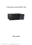
EA980 User Manual EA980 Series User Manual 10~60kVA DC±192V 1 EA980 User Manual Content Section I: EA980 Product System Overview ................................................................................ 3 1.1 Introduction ........................................................................................................................... 3 1.1.4 Separate bypass input ............................................................................................ 5 1.1.5 Static transfer switch............................................................................................... 5 1.2 Running mode ....................................................................................................................... 6 1.2.1 Inverter mode ............................................................................................................ 6 1.2.2 Battery mode ............................................................................................................. 7 1.2.3 Bypass mode ............................................................................................................. 7 1.2.4 Maintenance mode (manual bypass) .................................................................. 8 1.2.5 Parallel redundant mode (system multiplication) ............................................ 9 1.2.6 Hot backup mode ..................................................................................................... 9 1.3.1 EA980 Series UPS performance features .......................................................... 9 1.3.2 Product specific parameters ............................................................................... 10 Table 1: Specification ......................................................................................................... 12 1.3.3 Detailed instruction of function features ......................................................... 12 2.1 Introduction......................................................................................................................... 25 Section III: Installation of Battery.................................................................................................. 32 3.1 Introduction......................................................................................................................... 32 3.2 Safety .................................................................................................................................... 32 3.3 Battery cabinet ................................................................................................................... 33 3.3.1 Introduction ............................................................................................................. 33 3.3.2 Environmental temperature ................................................................................. 34 3.4 Power cable of battery ..................................................................................................... 35 3.4.1 Installation of battery ............................................................................................ 35 3.4.2 Battery connection................................................................................................. 36 Section 4:Installation and Testing of Parallel System .......................................................... 38 4.1 UPS single machine of parallel system ....................................................................... 38 4.2 The procedure of parallel system testing ................................................................... 40 4.3 Testing item of parallel system ...................................................................................... 40 4.4 Special notice ..................................................................................................................... 41 Section V: Operation Procedure.................................................................................................... 41 5.5 Procedures of emergency power off (EPO)................................................................. 43 5.6 Automatic start-up ............................................................................................................. 43 5.7 Language select................................................................................................................. 43 5.8 Change current date and time ........................................................................................ 43 Section VI: Operational & Controlling Display Panel .............................................................. 45 7.1 Introduction......................................................................................................................... 45 2 EA980 User Manual Section I: EA980 Product System Overview 1.1 Introduction 1.1.1 Brief introduction of EA980 3/3 High Frequency UPS EA980 (DC±192V) series is dual-DSP control technology using high-performance, all-digital UPS, Rectifier with power factor correction, its performance indexes reach the industry leading level. Power level covers 10~ 60kVA. EA980 UPS connection between the mains and the critical loads, providing high-quality power for the load. It uses high-frequency dual-transform pulse-width modulation (PWM) and digital control (DSP) technology, whatever change and interference from the mains input voltage & frequency that can not affected the output voltage. 1.1.2 Main topology Figure 1: Main topology configuration for the single unit 3 EA980 User Manual 1.1.3 System configuration This series of UPS composing by input/output circuit breaker, input/output EMI filter, rectifier, inverter, static switch, batteries, maintenance bypass switch and so on. Shown in Figure 2, the main input AC power supply by the CB1, through the input EMI filter into the rectifier module, rectifier to transform alternating current to direct current then into the PFC power factor correction circuit, power to inverter, this inverter is transformed this DC power to a pure & uninterrupted AC power. If the mains power is out of range or power off, then connect the battery with the static switch, from the PFC to rise voltage to DC bus voltage, DC bus using inverter supply the load power. Inverter failure or overtime of overload, it still can supply the power from external AC bypass by input circuit breaker CB2 and static bypass to the load. In addition, for maintenance or repair of the UPS, it can supply power from the internal manually bypass by circuit breaker CB3 to the load. Please turn on all the switches (excluding the maintenance bypass switch), when the UPS running normal. The whole system is using the full digital DSP control, UPS inverter control. Phase synchronization, input rectifier control, logic control and so on, those are using DSP digital signal processing, therefore high precision, high speed, simple control circuit and high reliable 4 EA980 User Manual CB3 Bypass CB2 Filter Input REC PFC INV CB1 CB4 Output Bat. Charge Figure 2: Schematic diagram for the single system 1.1.4 Separate bypass input Figure 2 describes the schematic diagram for the EA980 UPS with the “separation of bypass power”(that bypass using the independent mains power input). In the separation of bypass power configuration, the static bypass and maintenance bypass using the same individual bypass power, connect with a individual power switch and dedicated bypass power. If without the individual bypass power, should be shorted connect the bypass and rectifier input power terminals. 1.1.5 Static transfer switch Figure 2 shows the “static switch” including electronic control switch circuit, allows the load connected to the inverter output, or connected to bypass power by the static bypass. Under normal circumstances, inverter supply the load power; there have been overload or inverter failure, the load will automatically switch to the static bypass supply. In normal operation, the inverter output and static bypass must be fully synchronized, then can achieve seamlessly switch between the inverter and static bypass. Using the inverter control circuit to achieved the inverter output and static 5 EA980 User Manual bypass synchronous. The inverter output frequency always tracking the static bypass power frequency by inverter control circuit (when the static bypass power frequency in the allowed synchronous range). UPS also provides the manual control of the maintenance bypass. UPS can using the maintenance bypass supply the critical loads power, when the UPS need routine maintenance and repair. 1.2 Running mode True online double conversion EA980 series UPS system has the following working mode: Inverter mode Battery mode Bypass mode Maintenance mode (manual bypass) Parallel redundant mode (system multiplication) Hot backup mode 1.2.1 Inverter mode Bypass Filter REC PFC INV Input Output Bat. Figure3:Inverter mode When the mains is normal, the input AC power is inverted by rectifier, then the UPS will provide load with pure and stable AC power through output static switch, meanwhile, the UPS charges the battery. 6 EA980 User Manual 1.2.2 Battery mode The battery through the Cell pressurization circuit into the inverter, and provide backup power to the load from the inverter, this operational mode calls battery mode. When the mains failure, the system will switch to battery mode automatically, continue providing load power. When the mains recover, the system will switch back to normal running mode automatically, no need manual intervention and the load power never interrupt. Bypass Filter REC PFC INV Input Output Bat. Figure 4:Battery working mode 1.2.3 Bypass mode When inverter is abnormal, such as overload or be turned off by manual, UPS will turn off the inverter automatically and turn on the bypass static switch and then the bypass will supply the power to load. 7 EA980 User Manual Bypass Filter REC PFC INV Input Output Bat. Figure 5:Bypass mode 1.2.4 Maintenance mode (manual bypass) When UPS is under the situation of reparation or maintenance, in order to make sure keep providing continuous power supply to the load, the user should make the UPS turn to bypass working mode and turn on maintenance bypass switch, then turn off the UPS input/output switch and battery switch, therefore the UPS will enter into maintenance mode, shows as the arrow indicated in the figure. It is safe to repair the UPS as there is no electricity in the inner UPS at this time. The manual bypass switch is located inside the standalone UPS, its capacity can meet the total load capacity requirement of UPS. Bypass Filter REC PFC INV Input Output Bat. S. Figure 6:Maintenance mode (manual bypass) 8 EA980 User Manual 1.2.5 Parallel redundant mode (system multiplication) In order to improve the system capacity or reliability, or to improve both of them, we can set couple of single UPS to parallel UPS, The parallel control logic in each single UPS can ensure all the single UPS divide the loading automatically. The parallel system can make up with 6 units single UPS at most. 1.2.6 Hot backup mode This is a 1+1 parallel mode, it can improve the system usability and reliability. Two units single UPS hot backup mode: UPS1 connects to the major loading, UPS2 connects to the bypass. The other AC inputs of the system connect to the utility power. UPS1 & UPS2 Output synchronization, ensure the load power do not interrupt when the load transferring between UPS1&UPS2. This mode can ensure the UPS meet the power requirement for specified load, meanwhile, it can offer stabilized voltage and frequency to the bypass. 1.3 EA980 Series Features 1.3.1 EA980 Series UPS performance features Three phase input and output to support the power system of 380/400/415V, 50/60Hz. Pure online double conversion to support the optimal power supply quality Applicable for all kinds of load and possess high overload capacity Double DSP fully digital control to realize the full digitalization of the IGBT rectification, inversion, charge and discharge converter. For the latest IGBT rectification technology, the input power factor is up to 0.99; features low harmonic current, green environmental protection, high efficiency and energy-saving. 9 EA980 User Manual Digital circulation technology with the small circulation and the parallel reliability is high Super wide input voltage anti-interference range to adjust to the rugged power system environment Intellectualized battery management to prolong the service life of the battery Self-diagnostic function; abundant and perfect fault protection function; possess 10000 historic records to be inquired Fully positive maintenance and install the equipment near to the wall to save the equipment room space Cooling fan redundant design of the power module to improve the system reliability Similar modular design and the site maintenance is convenient and rapid Ultralong mean time between failure (MTBF) (>200,000h) Short mean time to repair (MTTR)(<0.5 h﹚ Huge LCD interface display and friendly human-machine interface Two routing modes of top incoming and bottom incoming Whether equip the output transformer can be selected Options: Main path reverse protection, bypass reverse protection, battery leakage protection, battery cold start and lightning protection components 1.3.2 Product specific parameters Capacity(Power-KVA) Input voltage Main input 10 20 30 40 60 380V/400V/415V(line voltage) Input mode Three-phase four-wire Power factor >0.99 Total Harmonic Distortion, Harmonic current(THDI) <5% 10 EA980 User Manual Voltage Range (Phase voltage/Line voltage) 120/208V~284/492V 160/277V~284/492V,Full load 120/208V~160/277V,derating 50% load operation Frequency range 40~70HZ Input voltage Bypass input 380V/400V/415(line voltage) Input voltage range +20%~-50%(settable) Input mode Three-phase four-wire Frequency range 40~70HZ(settable) Steady state voltage precision (balanced load) Dynamic voltage transient Voltage distortion THDU (linear load) Voltage distortion (non-linear load) ±5%(0~100% variation in load) THD<3%(phase voltage) THDU Power factor Output ±0.5% THD<5%(phase voltage) 0.8(lag) Frequency tracking range 50Hz±3Hz Frequency precision (battery inversion) ±0.05Hz Three-phase separation Frequency tracking rate Inverter overload capacity 120±0.5°(balance or unbalance load)) 0.5Hz/s~5Hz/s(settable) 105% load, long time operation; 125% load,transfer to bypass after 10 minutes; 150% load,transfer to bypass after 1 minutes; >150% load,transfer to bypass after 1 minutes; 11 EA980 User Manual Bypass overload capacity <150% load,long time operation; 150%<load< 180% ,last for more than 1 minutes; load>180%,last for more than 1 minutes. Normal switching time utility battery:0ms,bypassinverter:0ms Overall working efficiency Normal:>90%,ECO mode: 98% Display LCD+LED EMI IEC62040-2 EMS IEC61000-4-2(ESD) IEC61000-4-3(RS) IEC6100-4-4(EFT) IEC6100-4-5(Surge) Noise (1m) <60dB Insulation resistance >2M(500VDC) Insulation strength (Input and output ground) 2200Vdc; leakage current is lower than 3.5mA, 1min without flashover Surge protection Meet System the Ⅳ installation location requirement of IEC60664-1, that is, the ability of bearing 1.2/50us+8/20us combination wave is not lower than 6KV/3KA Battery 12V battery 32 PCS (positive battery:+192VDC,negative battery:-192VDC) Connection mode Top and bottom incoming and outgoing Machine size,W×D×H(mm) N.W without battery(kg) 620*800*1445 220 Color black Protection degree IP20 240 250 260 280 (IEC 60529) Table 1: Specification 1.3.3 Detailed instruction of function features 12 EA980 User Manual 1.3.3.1 Rectifier: (1)、 Power factor correction Rectifier possesses the power factor correction function. Under the condition of output full load, the input power factor is larger than 0.98 and the input current THD is smaller than 8%. Figure 7: Input voltage and current waveform (2) DC bus soft start-up Rectifier can realize the soft start-up of the direct current bus voltage to ensure that no impact current to the bus capacitances (3)Protection and alarm of rectifier Main input abnormal If any phase voltage of input is lower than 160V or higher than 280V, the rectifier will be closed, UPS will switch to the battery mode and the LCD will display the alarm messages. Input frequency abnormal If the input frequency exceeds the range of 40~70Hz, the alarm single of the input frequency abnormity will be reported, the rectifier will be closed, UPS will switch to the battery mode and the LCD will display the alarm messages. Phase sequence reverse protection function of the main input If the input phase sequence reverse is detected before the starting of the rectifier soft start, the rectifier will not start and the LCD will display the alarm 13 EA980 User Manual messages. DC bus low voltage and over-voltage protection Software protection point: When the voltage of the positive bus or negative bus is lower than 290V, UPS will switch to the battery mode. If the voltage of the positive bus or negative bus is lower than 290V or higher than 410V, the rectifier will be closed. Hardware protection point: When the voltage of the positive bus or negative bus is higher than 410V, the rectifier, inverter and battery converter will be closed. If the bypass is within the protection range, the load will switch to the bypass power supply. The LCD will display the alarm messages. Pulse by pulse current limitation If the rectifier current is larger than 3 times of the peak value of the rated input current, the rectifier will undergo wave chasing and current limiting. Heatsink over- temperature protection Each IGBT temperature is monitored. If the IGBT base plate temperature is higher than 85±5℃, the rectifier will be closed and the LCD will display the alarm messages. Over- temperature protection of the input inductance When soft start finished ,but positive bus and negative bas still lower than rectifier voltage or battery voltage, it will showing soft start fault and alarm Input over current protection If the input current of the rectifier is larger than 4~6 times of the IMAX current limit (effective value), the rectifier will switch to the battery mode to supply the power. The LCD will display the alarm messages 1.3.3.2 Battery (1) Charge When the rectifier is running, the battery converter intelligently charges to the battery under the normal commercial power. 14 EA980 User Manual The conversion of the constant-current charge, constant voltage charge and float charge can be realized automatically and smoothly. The battery type includes the valve-regulated lead acid battery, nickel-cadmium battery and wet battery. (2) Discharger When the rectifier is closed or under the condition of the input over current, the battery converter will supply the power to inverter. (3)Protection and alarm Battery discharge interruption (EOD) protection If the battery voltage is lower than EOD shutdown point, the battery converter will be closed. The EOD shutdown point is 1.75V If battery charger temperature higher than 85 ±5℃, battery charger will be turn off. If battery charger voltage abnormal, it will alarm also and also showing the alarm information. 1.3.4 Inverter and Bypass (1) Inverter has big strong overload capability: 105% load, working normally 110%--125%load,after 10 mins to switch to bypass; 125%--150% load, after 60s to switch to bypass >150% load, after 1s to switch to bypass Between 105% to 50%, close inverter according to overload curve 15 EA980 User Manual Figure 8:overload curve Overload capacity is so strong: <180% load,working normally, Load >180%,work for 1s (2) Inverter use advanced modern digital control mode, with a variety of load capacity, and the output voltage distortion become small: Figure 9:Inverter PF vector graph 16 EA980 User Manual Figure 10: Inverter with resistive load and rectifier load voltage and current waveform (3) Bypass range A. Switch Range Definition of the scope switch, inverter and bypass in order to achieve continuous and intermittent switching between the judge. Including the voltage amplitude range and frequency range. When the bypass voltage amplitude or frequency over range, the scope of all that pass beyond the switch. Voltage amplitude range is fixed at 187-253V range. Frequency range defined below. B. Bypass can track the scope When the bypass is within the scope of traceability, the mean bypass and inverter are synchronized state. Including the range of voltage amplitude and frequency can be within tracking range. When the bypass voltage amplitude or frequency range than can be tracked, all that could be tracked beyond the scope of bypass. Tracking range can bypass the default value is ± 5Hz. (4) Bypass is the scope of protection The scope of protection means can be available, when the bypass is in this state, any time bypass can’t supply power. Including amplitude and frequency range can protect the scope of protection. When the bypass voltage amplitude or frequency range than can protect all that can bypass beyond the scope of protection. Bypass may include a limit on the scope of protection and a lower limit. (5) Function A. Inverter on / off control Inverter can be opened manually by the user, or use the keyboard to clear the fault to open, or electricity restored automatically. Inverter can be closed manually by the user, or system failure shut down automatically. Some serious problems, 17 EA980 User Manual such as static switch failure may permanently close the inverter until the systems power. B. Output switching logic The system automatically switching logic for each switch the selection mode, switching logic synthesis bypass state, the inverter status and fault information to determine the switch mode. If the inverter is synchronized with the bypass state, then the inverter and bypass the phase difference between the less than 5 degrees. C. Parallel operation This series UPS supports up to six units to be parallel. Flexible and reliable operation of logic and computer system can guarantee high reliability and load stability. Parallel logic can coordinate all the inverter parallel system operating behavior (6) Protection and alarm Anti-bypass phase sequence protection If the bypass reversed phase sequence, then the system will default that bypass is super state protection, at any time the load can’t be powered by the bypass. Fault alarm has been existed until the systems power. Inverter heat sink over-temperature protection For each IGBT temperatures were monitored, if the inverter IGBT substrate temperature exceeds 85 ± 5 ℃, inverter will be shut down, turned to bypass the load power. IGBT temperature was down, the system automatically switch to main. LCD will display the alarm information. Inverter fault protection When the inverter has been opened after a certain time, if the inverter output voltage in excess of CBEMA curve, there will be that the inverter fault, the inverter will be shut down, the LCD will display the alarm information. UPS will switch to bypass. Inverter IGBT protection If any phase of the inverter appears (IGBT over-current), the inverter will 18 EA980 User Manual immediately shut down. LCD will display the alarm information. DC bus over-voltage or low voltage fault If any bus voltage higher than 410V, or less than 290V, and for some time, the inverter will be shut down, UPS will switch to bypass. Inverter overload switch Inverter overload situation, required sustained through some time, UPS will supply power through inverter switch to bypass. After Switched, the inverter is in hot standby. When overload disappears, the system will automatically switch inverter power supply. Inverter limited current little by little When the inverter rated output current of the peak current greater than 2 to 3 times as the inverter will be limited current. For example, after the output short circuit, the protection will work. Inverter is non-synchronized If the inverter can’t be synchronized with the bypass, will report this warning message. The current of Parallel system isn’t on average, If any UPS system in the uneven flow of a single degree of more than 30% will report this warning message. 1.3.5 Monitor 1. UPS basic information ●UPS Name ●UPS Model ●Working mode ●UPS Error information ●UPS Alarm information ● Current date and time The parameters listed below should be displayed on the LCD screen. All displayed 19 EA980 User Manual values should be refreshed within 5 seconds. The discrepancy between displayed value and actual value is less than 2% 2. Real-time data A. Mains input ● Voltages three phases of mains input ● Currents on three phases of mains input ● Frequencies on three phases of mains input B. Bypass input ●Voltages three phases of bypass ● Currents on three phases of bypass ● Frequencies on three phases of bypass C. UPS output ● Phase voltages on three phases of output ● Currents on three phases of output ● Load percentages on three phases of output ● Frequencies on three phases of output 5. Load information ● Active power on three phases of output ● Apparent power on three phases of output 6. Battery ● Positive battery voltage ● Negative battery voltage ● Positive battery current ● Negative battery current ● Single battery voltage 7. Bus bar ●Positive voltage of bus bar ●Negative voltage of bus bar 8. Working status 20 EA980 User Manual ● Working mode ● Voltage mode ● System running status ● Error information ● Alarm information 9. Record of the historical event ●When the fault appears, the record of the historical event should be updated immediately. 10. System setting ●Language selection(support 2 languages: Chinese and English) ● Date and time ● Communication setting 11.Manufacturer information ● Manufacturer ● UPS Model ● Capacity ● Controlling software ● Display software (2) LED display The power flow direction of the system is displayed by five LED. ● INPUT ● BAT ● BYP ● INV ● OUTPUT The green LED means UPS is working on AC mode, the yellow LED means UPS is working on battery mode and other 3 LED are for alarming. ●OVERLOAD 21 EA980 User Manual ●WARNING ●FAULT Yellow LED is for warning; Red Led is used for the fault alarm (3) Key-press There are seven keys on the panel which include four menu keys, inverter start-up key, inverter turn-off key, Emergency Power Off key ( EPO) ● The four menu keys can be used for choosing the menu screen displayed by the LCD. ● Inverter start-up key is used for starting the inverter. ● Inverter close key is used for turning off the inverter. ● Emergency power off key is used for the rapid shutdown in the urgent situation. (4) External interface UPS provide several interface communication methods including by RS232 one to one communication, long distance communication by RS485, and monitoring by dry contact. UPS have extended communication port which allows connections to SNMP card, SMS alarm management module, temperature and humidity monitoring module (options) in order to achieve long distance alarm and networking management. Communication software is mainly used for monitoring UPS working status, sending email, controlling of UPS and alarm records, timing on-off service functions and so on. Below are the instructions for each interface: ● RS232 communication instruction RS232 is for close communication one to one, normally the distance is less than 10meter, and pin functions are defined as below: DB9 port pin 1 2 3 4 5 6 7 8 9 NO RX TX NO GND NO NO NO NO no. definition 22 EA980 User Manual ● RS485 communication instruction: This UPS adopts communication method of dual line, several points, and dual directions, it allows long distance many to many monitoring; output communication cable adopts twisted-pair connection, three output lines are A (485+)、B(485-) and GND. ● USB communication instruction: UPS is with standard USB communication port including communication cable, it can meet the requirement of communication if there have no RS232, it is convenient to monitor and manage UPS in real-time. ● Dry contact communication instruction: The voltage and current of electrical independent contact is: AC 120VAC/1A or DC 24V/1A, output signal instructions are as below: Signal OVER BAT.LOW INPUT BYPASS definition FAULT BAT. LOAD Always Always Always Always Always Always open + open + open + open + open + open + always off always off always off always off always off always off Output UPS Battery overload abnormal mode action action actions Interface terminal Low AC input is battery Instruction Bypass normal voltage action action actions ● SNMP instructions SNMP card supports SNMP 、HTTP、TCP/IP protocol etc. It complete UPS monitoring thru monitoring software, NMS and Web browser (IE and NetScape etc) ● The instruction of SMS alarm management module UPS SMS Alarm Management Module not only with SNMP network management 23 EA980 User Manual function but also with SMS alarm function to meet these customer’s request on long distance management who is Inconvenient or does not build the network for monitoring adapter, and now urgent need for UPS remote management. SMS Alarm Management Module with UPS can solve the problem of no network for remote monitoring function of the UPS. When the UPS alarm condition occurs, when the to UPS will send alarm by text messages via cell phone GSM network to the administrator, without using wide area network. Figure 12:Networking topology structure and networking building solution diagrammatic sketch 24 EA980 User Manual Section II:Installation of Single Machine System 2.1 Introduction This section introduces the necessary requirements for UPS placement and wire routing. For the particularity of each site, this section does not introduce the detailed installation procedure but support the general instructional installation steps and methods to customers. The installation personnel need to manage it according to the specific situation on site. 2.2 Environment Selection ·Operation temperature:0-40℃ ·Storage temperature:-40-70℃(No battery connected) -20-55℃(Battery connected) ·Relative humidity:0%~95%,(No-condensing) ·Altitude:1500m,(comply to GB3859.2-93 standard) ·Tolerance of verticality:no vibration、jounce,vertical gradient <5° UPS system installation environment should be cool and clean enough with good ventilation, dust-free and low humidity. The optimal working environmental temperature for UPS is 20~25℃, while humidity is 50% or so. Power descending usage is advised and referred as below at altitude above 1500m. Altitude(m) 1500 2000 2500 3000 3500 4000 4500 5000 100% 95% 91% 86% 82% 78% 74% 70% Descending coefficient 2.3 Placement AC power provided in UPS room should meet the requirement of UPS working. Equipped with dedicated input and output circuit breakers, UPS can not share breakers with other power units or equipments. UPS should be installed as close as possible to the AC power distribution 25 EA980 User Manual outlet. The floor taken the UPS should be able to stand the weight and dimension. Any other dangerous installation is forbidden. In UPS room,fire fighting equipments are required while storage of flammable, explosive and other dangerous goods is forbidden. Keep good ventilation around UPS to prevent obstructing the cooling channels of UPS. Keep adequate space all around the UPS for future free maintenance and operation.(1 meter at least) It is recommended that there should be a professional or technician for UPS room management, non-professional or unqualified people is forbidden to enter in. 2.4 Unpacking Before unpacking, inspect if any damage on the package due to the transport process and check the product model label. Unpack the package and check if all the accessories are included and real product inside is right for you. 2.4.1 Accessories User manual, 1pc; CD for monitoring software, 1pc; Cables for RS232 and USB interface, each 1pc; 2.4.2 UPS specification confirm Make sure the following parameters can meet your requirements,such as UPS capacity, voltage and frequency of input and output , phase of input and output, DC voltage and so on. 2.5 Structure instruction 26 EA980 User Manual Fig.13 Overall profile The air flow inside of the UPS is directed from bottom and side to coping. Please keep adequate space for good ventilation. Place the UPS well and then stamp down the brake near the front wheel to prevent shifting itself. 2.6 Breaker, Cable’s selection The cable for different capacity of UPS has different grade, unsuitable cable or air circuit-breaker will cause danger. The selection principle for power cable’s density is: 3-5A/mm2 for middle and small power UPS, 2.5-3A/mm2 for big power UPS. Meanwhile, note that the maximum voltage within the power cables to be chosen should be not more than 3V. There are neutral wires both for input and output of UPS system. For the UPS with triple phase in and out, the cross-sectional area of input neutral wire should be 1.5-1.7 times of phase wire or live wire. UPS system has grounding wires for safety protection and lightning protection 27 EA980 User Manual whose cross-sectional area should be 0.5-1.0 times of phase wire and not less than 6mm2. 2.6.1 Breaker selection Input Model voltage Max Max input input current current A A Output voltage V AC Input Output breaker breaker A A V AC EA9810 220 220 22 15 50 50 EA9820 220 220 44 30 63 63 EA9830 220 220 66 45 80 80 EA9840 220 220 88 60 100 80 EA 9850 220 220 110 75 125 100 EA9860 220 220 132 90 150 125 Note: Abandon the breakers with leakage protection. 2.6.2 Power cable selection(Unit:mm2) E R Output S T 6 6 6 6 6 6 10 10 6 6 6 6 6 6 6 10 10 10 10 10 10 10 10 10 10 20 20 16 16 16 16 16 16 16 16 16 30 30 EA 9850 25 25 25 25 25 25 25 25 25 50 50 EA 9860 25 25 25 25 25 25 25 25 25 50 50 Model Input T N R S EA9810 6 6 6 EA9820 6 6 EA9830 10 EA9840 BAT N + - Note:The real cable applied should be no smaller than the figures in the table above. 2.7 Terminals instruction All the terminals are on the front panel and bottom of UPS case. See the figure below for details on terminals plate: 28 EA980 User Manual Fig.14 Terminal blocks profile 2.8 Installation and Checking 2.8.1 UPS checking After UPS installation, please inspect following items: Whether the brake near the front wheel fixed, steady or skew. Whether scratch or hit damage on he UPS. Whether there are sundries around the UPS body. 2.8.2 Cables’ connection After the complete position of the UPS, link the power wires as below: 1. Completely cut off all input distribution switches and UPS circuit breakers. Stick the warning mark in these switches to avoid other people operating them. 2.Open the UPS door and take down protection cover downside the UPS, viewing the copper bars for the power cables connection. 3. Connect the protection grounding cable or other necessary earthing cable with the earthing copper bar at the bottom of UPS, making the whole UPS cabinet grounded at user’s site. 29 EA980 User Manual Note: The connection of the ground wire and the nutral wire should comply with the relevant standard from local and the state. Choosing either of the following two steps, mark and connect the input cables based on installation type: Choosing either of the following two steps, mark and connect the input cables based on installation type: Mutual input connection With rectifier input and bypass input sharing the same power source, customer need to connect the AC power cables with the UPS rectifier input terminals (main Live path A-B-C, input N). Ensure the correctness of the phase sequence. Separate bypass connection For the rectifier input and bypass input with separate or different power source, connect one group power cables to the rectifier input terminals (main path A-B-C) while connect the other to the bypass input terminal (bypass A-B-C). Ensure the correctness of the phase sequence. Note:For the later system with bypass and rectifier input using separate or different power source, dismantling the copper bars short connected between the bypass and the rectifier input and connecting the neutral wire of the bypass input and rectifier input together is required. System output connection Connect the system output cables between the UPS output terminals (output A-B-C- N)and load. Present commissioning engineer should properly manage to make the terminal of the system output cables safely insulated well if the load is not ready to accept power. External battery connection Connect battery cables between the battery terminals (+\-) of UPS and battery switch on battery cabinet. Pay attention to the polarity confirmation.. Note: Linking from battery switch to battery terminals is considered as the normal 30 EA980 User Manual procedure. 2.8.3 Double checking after connection 1) The input and output power distribution switches should be fit for the UPS. Both input and output terminals on PDU are supposed to be canonical and regulated. 2) Make sure the input and output power cables connected or fixed well with correct phase sequence and label. 3) Make sure battery cables fixed well with correct polarity link after batteries placed steadily. 4) Make sure system wiring canonical and regulated for free maintenance and expansion in the future. 31 EA980 User Manual Section III: Installation of Battery 3.1 Introduction UPS assembled battery is connected by several batteries in series to provide the rated DC input voltage for UPS inverter. The required battery backup time (duration of load power supply when the utility is interrupted) is restricted by the ampere hours of battery. So it needs to connect several batteries in parallel sometimes. The provided battery cupboard has the following forms: 1. Complete set containing battery cupboard, battery and protection components; 2. Only contain battery cupboard and protection components-no battery; 3. Only contain battery-no battery and switch It may need to disconnect the battery and UPS when maintain or repair the equipment. The switch of the battery can be disconnected or closed manually. The switch off control can be realized through the under-voltage coil of battery switch or release. 3.2 Safety The operation of the battery of EA980 UPS system shall be particularly careful, because the voltage of the battery is deadly when connect all the single batteries. With regards to safety, the external battery shall be installed in the cabinet with lock or special designed battery chamber to separate from the personnel (except for the qualified engineer) Note: The note related to the use and maintenance of battery is instructed in the battery manual provided by the manufacturer. The note relevant to battery safety mainly includes the necessary events in the installation and designing process; it may be adjusted according to the local situation. Warning: 32 EA980 User Manual The user cannot operate the parts that needed the tools to open behind the protection lap, only the qualified personnel is permitted to open this type of protection lap. Besides, please disconnect the internal battery before operating the isolation terminals used for connecting external battery. The following safety notes shall be paid attention when use battery: 1. There is the electric shock when use battery. Large short circuit current can cause fire danger. 2. The voltage of the assembled batteries is 480Vdc with deadly danger, so please comply with the safety notes of high voltage operation. 3. Only the qualified personnel can install and maintain the battery. 4. Wear the eye shield to avoid the accidental injury of arc. 5. Take down the ring, watch, necklace, bracelet and other medal ornaments. 6. Use the tools with insulated handle. 7. Wear the rubber glove and apron when use battery. 8. The leaked or damaged battery shall be put in the sulfate resistant container, and it shall be disposed as scrap according to local regulations. 9. Immediately clean the skin if it contacts the electrolyte. 10. Scrap disposal of the battery shall comply with the local environment laws. The quantity of new battery and old one shall be the same when replace the battery. 3.3 Battery cabinet 3.3.1 Introduction This battery cupboard can be used together with other machine cabinets, so that it can contain more batteries to provide the system longer backup support time. If there are two or more battery cupboards, which shall be installed side by 33 EA980 User Manual side and mutually connected. Besides, it suggests connecting the batteries in the general output end in series after paralleling the breakers output end of battery cupboards. 3.3.2 Environmental temperature Valve control lead accumulator is very sensitive to temperature, so the valve control battery shall be used within the temperature of 15℃~25℃. When the temperature is below 25℃, the environmental temperature increases 1℃, the battery capacity will increase 1%. Therefore, use the battery above the temperature of 25℃ will shorten its service life. If the battery and UPS are installed in one room, the maximum design environmental protection shall be determined by the battery, not UPS. That is to say, if use the valve control battery, the indoor temperature shall be within 15℃~ 25℃, not 0℃~40℃ (it is the regulated working temperature range of main equipment). The temperature is allowed the deviation in a short time on the premise that the average temperature doesn’t exceed 25℃. 3.3.3 Structural map of battery cabinet 34 EA980 User Manual Fig. 15:Structure of battery cabinet 3.3.4 Battery connection diagram Fig. 16:Battery connection 3.4 Power cable of battery 3.4.1 Installation of battery 35 EA980 User Manual 1.Generally, the space between the vertical surface and the sides shall be at least 10 mm, which can make the surrounding air freely flow. 2.There shall be a certain space between battery top and the above barricade to facilitate the monitoring and maintenance of battery. 3.The battery shall be installed from the bottom to the top to avoid the top-heaviness. 4. There shall be retained more than 1 meter’s space around the battery cupboard, which can facilitate the maintenance and air flow. 3.4.2 Battery connection 1.When the battery cupboard is installed on the elevated floor, the power cable of battery and the battery switch-controlled cable can enter UPS cabinet from the bottom. If UPS is installed adjacently to the battery cupboard on the solid floor, these cables can pass through the machine cabinet through the underside incoming hole of battery cupboard. 2.Generally, it suggests connecting the cables between the same-layer batteries first, and then connecting the cables between the layers, finally connecting the battery switch and battery terminals. 3.Install the insulating cover to the terminals after connecting the battery terminals. 4.Connect the switch end first when connect the battery terminal and cables between the battery switches. 36 EA980 User Manual 37 EA980 User Manual Section 4:Installation and Testing of Parallel System The installation of parallel machine shall comply with the installation procedures of the single machine system and the requirements of this section. 4.1 UPS single machine of parallel system Put single machine side by side, and install them according to the Fig. 1. Because of no external bypass cabinet, so we should connect input and output of every UPS together. Pay attention to the correction of the phases connection. That’s to say the input phase A of 1#UPS should connect to the 2#UPS’s,the input phase B of 1#UPS should connect to the 2#UPS’s, the input phase C of 1#UPS should connect to the 2#UPS’s. The sequence of the phases A,B,C is the same with the single UPS. And the same way to connect the output phases, then connect the loads. The connection way of battery cabinet is the same with the single UPS. They can’t share battery pack. 38 EA980 User Manual Fig. 1:Typical 1+N system principle diagram All the parallel cables is double insulated shielding parallel controlled cable with 25 pins, it can form a closed loop as the Fig. 2 shows. Paralleling panel 39 EA980 User Manual Fig. 2:Schematic diagram of parallel signal cable’s connection 4.2 The procedure of parallel system testing 1. Connect the input cable 1) Turn off the mains breaker and connect the AC power to the terminal of each UPS in the correct phases order. Each UPS should connect the battery (the connection method is the same with the single UPS). 2) The parallel cable is the standard double insulated shielding parallel controlled cable for the machine. Use the parallel cable connect all the UPS refer to the Fig. 2. 3) The output power cable of each machine is connecting to the load .(The connection method is the same with the input.) 2.The test of start-up 1) Turn on the N switch, AC-input breaker and bypass breaker of all the UPS. Turn off output breaker of all the UPS. The power boards start to work and the LCD will show welcome interface. The “INPUT” light up, when you turn on the bypass switch, the “BYP” light and “OUTPUT” light up. The UPS will change to the BYPASS mode. 2) Start-up. Pressing the ON button more than 1 second, after 10 seconds UPS will be inverter output, the “INV” light up. 3) Measure the each phase voltage in the output breaker, and compare the relative phase voltage with the other UPS. If the voltage difference within 0.5V, you can turn on the output breaker of all the UPS. Then the machines can work normally with load. 4.3 Testing item of parallel system 1) Test the equalized current Check the display panel after the parallel system with load, the difference of the load capacity for each machine is less than 5%. 2) Test of turn-off The two machines take 50% load after parallel, turn off one of them, the other should take the entire load. After we restart the machine which was 40 EA980 User Manual off , they can share the load again. 3) Transfer between AC and battery After parallel, two UPS take 50% load ,transfer mains and battery of them .When connect the AC at the battery mode, should turn off the battery breaker after 2 seconds(it needs 2 seconds for testing after connecting to the AC in order to make sure the AC is in normal, not disturb ). 4) It is the same way when you connect more than 2 machines. 4.4 Special notice 1) Never pull out the parallel cable when the parallel system is under the normal operation. 2) Try your best to turn on all the machines after all of them connect to the AC. If you can’t do this, you need to behave hot-plug, turn off all the inverters (switch to the bypass output mode) before you get a new UPS parallel. 3) It is forbidden for the parallel system to share the battery pack. 4) The full load capacity of parallel system should not take the full load capacity of N-1 UPS. For example, the load capacity of 2 parallel UPS shouldn’t be more than the full load capacity of one UPS, the 3 parallel UPS shouldn’t over the full load capacity of 2 machines ,the 4 parallel machines shouldn’t over the full load capacity of 3 machines . The function of the parallel redundancy system will be no use when the load capacity is over. Section V: Operation Procedure After installing and debugging of the authorized maintenance engineer, UPS can be run according to the mode of Section II. This Section describes the operation procedures in various running modes for the operator, including the start-up procedures of UPS, the operation procedure to shift the load to bypass and the power-off procedures of UPS. Note 1: Please see the user’s operational key and LED display related to the operation procedure in Section VI Note 2: Please see all the power supply switches in UPS cabinet (visible when open the front door of cabinet, with lock ) in Fig. 14. 5.1 Preliminary of start-up 1) Make sure all connection wires and power source is correct before start-up. 41 EA980 User Manual 2) Check if input voltage and frequency is within UPS range. 3) Check if all the UPS switch is under close-up status. 5.2 Start-up procedure 1) Turn on battery switch. 2) Turn on AC input switch, the power supply board start to work, LCD display “welcome”, “INPUT” lights up. Turn on bypass switch, bypass “BYP” lights up, output “OUTPUT” lights up, UPS gets into bypass status. 3) Start UPS. Press key ON longer than 1 second, After about 10 seconds, UPS switch to inverter output, “INV” lights up. 4) Turn on output switch. 5.3 Procedures of power off 1) Close up output switch. 2) Shut down UPS. Press key OFF longer than 1 second. 3) Shut down battery switch. 4) Shut down bypass switch. 5) Shut down AC input switch. 5.4 Procedures of maintenance bypass This procedure must be operated by professionals, unauthorized person are forbidden to do this work, offenders at their own risk. 1) Turn off inverter. Press key OFF longer than 1 second, UPS switch to bypass power status, BYPASS lights up. 2) Open the rear cover board of circuit breaker, start upwards the manual maintenance switch. 3) Turn off UPS input switch, battery switch, bypass switch and output switch. 42 EA980 User Manual 4) Do and finish UPS maintenance work. 5) Turn on UPS output switch. 6) Turn on bypass switch, input switch and battery switch. BYPASS lights up. 7) 8) Turn off manual maintenance switch. Turn on inverter. Press key ON longer than 1 second, after 10 seconds, UPS gets into normal working mode. 5.5 Procedures of emergency power off (EPO) The emergency power off (EPO) switch is used in the emergent situation (such as fire and flood, etc.) to turn off UPS. The system will turn off the rectifier and inverter, and immediately cut off the load supply (including the inverted and bypass output). Moreover, the battery stops charging or discharging. If there is still the Mains power input to UPS, the control circuit of UPS is still electrified, but the UPS output is turned off. If it needs to completely shift the commercial power supply of UPS, the external input switch of commercial power shall be disconnected. First, it needs to completely disconnect UPS, it is to disconnect the input switch manually, and then UPS can exit the emergent power off situation. 5.6 Automatic start-up When the Mains power is interrupted, UPS supplies the load through the battery system, until the battery discharge reaches to the end-of discharge voltage (EOD), UPS stops the output. When the Mains power recovers, UPS can start up automatically and recover the output supply. 5.7 Language select LCD menu and data have both English and Chinese display. The setting can be selected through the menu of panel. 5.8 Change current date and time This can be set up through the menu of panel. 43 EA980 User Manual 44 EA980 User Manual Section VI: Operational & Controlling Display Panel 7.1 Introduction UPS’ operation display screen is in front panel; user can set and check all UPS’ parameter, UPS & battery working status, event and alarming information. It can divide into three parts according to function difference: simulation state diagram, LCD display and menu key, and control & operation key. 7.2 Functional operation key (5( (6( (7( (4( (3( INPUT (2( (8( (9( BYP BAT INV OUTPUT OVERLOAD WARNING FAULT (10( (11( ESC EPO (1( UP ON DOWN OFF (12( (13( (14( (15( (16( ENTER Fig. 20: UPS operation & control and LCD display panel (1)— Display UPS working parameter and status. (2)— Battery output indicator (blue), light when battery supply power to UPS. (3)— Mains power input indicator (blue), light when mains power normal. (4)— Bypass output indicator (blue), light when UPS output is in bypass mode. (5)— Inverter output indicator (blue), light when Inverter is working. (6)— Output indicator (blue), light when inverter or bypass work normally. (7)— Overload warning indicator (yellow), light with alarm when UPS overload in bypass or inverter mode. (8)— Warning indicator (yellow), light with alarm when UPS has fault at working. (9)— Fault warning indicator (red), light with alarm when UPS has fault. (10)— “Back” button, press it to back to last page or exit, used to back to last 45 EA980 User Manual menu or cancel the parameter setting. (11)— “EPO” , press it for turn off UPS in emergency. (12)— “Scroll up & select key", use to scroll up and browsing multiple lines text. (13)— “ON” , press it more than 1 second, the UPS will start. (14)— “Scroll down &select key", use to scroll down and browsing multiple lines. (15)— “OFF” button, press more than 1 second, the UPS will turn off. (16)— “Enter”, press to confirm where the cursor points or parameter setting. 7.3 Menu description (1)When UPS connect with Mains power, LCD screen show as below Clarification: after 2sec, it will enter “WELCOME” interface. TO BE A SUSTAINABLE GLOBAL BRAND ONLINE UPS PLEASE WAIT! (2)“WELCOME” interface. Clarification: every interface hold on more than 5min, or press “ESC” in sub-interface, it will back to “WELCOME”. If UPS system has fault, it will highlight corresponding fault. (3)Main Menu interface Clarification: through up and down key to select the sub-interface, then press “ENTER” to access to it, the selected one will be highlight. 46 EA980 User Manual ON-LINE UPS ON-LINE UPS INPUT AC STATUS INPUT BYPASS HISTORY LOG OUTPU SYSTEM SET LOAD MANUFACTURE INFO BATTERY BUS (4)Input Mains parameter ((( I N P U T ( VOLT (R AC (S (T 2 2 0V 2 2 0V( 2 2 0V (((((( 5 0 . 0Hz ( ( : (( FREQUENCY ( I ( : 2 . 0A ( MAX VOLT ( : 2 8 0V ( MIN VOLT : 1 8 0V ( (5)Input bypass parameter ((( ( VOLT INPUT BYPASS (R (S (T 2 2 0V 2 2 0V( 2 2 0V (((((( 2 . 0A ( ( : (( FREQUENCY ( I ( ( : 5 0 . 0 Hz ( ( ( (6)Output parameter 47 EA980 User Manual (((((( ( OUTPUT ( (R (S ( VOLT 2 2 0V 2 2 0V( 2 2 0V (((((( ( 0 A((0 I ( FREQUENCY LOAD ( ( (T A 0 A 5 0 . 0 Hz ((( 0 0 0% 0 0 0% (( 0 0 0% (( (7)Load parameter (((((( ( (R LOAD ( (S (T ( ((((( ( ACTIVE POWER (KW(: 00 . 0 0 0 . 0(( 00 . 0 APPARENT POWER(KVA): ( (( 00 . 0 0 0 .. 0(( ( 00 . 0 (( (8)Battery parameter ((((( BATTERY ( ( POSITIVE ( NEGATIVE BATTERY ( (( ( BATTERY ( ( DISCHARGE CURRENT ( CHARGE CURRENT ( (((((((( ( BATTERY CAPACITY ( ( ( (9)Bus parameter 48 EA980 User Manual ((((( BUS ( POSITIVE BUS : V ( +3 6 0 ( ( NEGATIVE BUS : - 3 6 0V (( ( (((((((( (((((((( ( ( ( (10)Working status 49 EA980 User Manual STATUS WORK MODE : POWERON VOLTAGE MODE : 3IN 3OUT SYSTEM FAULT : NORMAL CODE : 000 WARNING CODE : 000 (11)Historical record interface Clarification: it can keep 500pcs historical record, the latest record show on the first, showing method: month+day+hour+minuit+second+event code, if record more than 500pcs, the earliest one will be cover., each page shows 6 record, user can press “UP” and “Down” to check more record. ((((( H I S T ORY ((((((( 02 - 21 18 : 1 8 : 11 UPS OF F 0 2 - 21 18 : 17 : 1 1 BAT MODE 02 ((((( - 21 18 : 16 : 11 BAT T E S T MODULE 02 - 21 18 : 15 : 1 1 RS I NV . V SHORT ( (12)Setting interface 1)Main interface of setting 50 EA980 User Manual ((((( SETTING ( > ( LANGUAGE SELECT (( DATE&TIME SET COMMUNICATION SET ( ( 2)Interface of language selecting ((((( ( LANGUAGE (( ( ( () ( > (( ( CHI NESE ) ENGL I SH( (( ) ( ( 3) Interface of time setting DATE&TIME SET ((((((((( ( ( DATE : 1 0 - 0 3 - 0 3 > (( WEEK ((( F R I TIME : 1 0 : 1 0 : 0 0 (( ( ( 4)Interface of communication setting 51 EA980 User Manual COMMUNICATION SET ((((((((( ( ( ( ( ( EA MODBUS PROTOCOL > ( COM ADDR (( BAUD RATE 1200 : 021 ( bp s ) : 2400 4800 9600 ( 52 EA980 User Manual Section VII: Daily Maintenance 7.1 Battery use and maintenance 1) Please assure battery working environment temperature is 20-25℃, it can extend battery span life. 2) Please regularly check battery pole and battery head, see whether it’s firm connect. 3) Please clear dust on battery regularly to avoid short circuit. 4) Please use wet cloth when clearing battery, do not use organic solvent. 5) Please regularly check single cell, see whether cell voltage normal, if not, please replace in time. 6) Please regularly check battery, see whether it’s bulge or leakage, if had, please replace in time. 7) Please use same brand and same capacity battery as previous one when replacing battery, do not mix old and new. 8) If long time no mains power failure, please do regularly artificial discharge once per 4~6 month, and discharge capacity should be controlled around 50% of battery capacity 9) Do not discharge battery by small current, to prevent small current deep discharge to damaged battery 7.2 UPS maintenance 1) Please regularly check UPS input/output wire, see whether connect well, any damage. 2) Please regularly check UPS working situation 3) Please regularly check UPS fan, to avoid debris blocked outlet. 4) Please regularly clear UPS inside, to avoid UPS failure caused by too much dust. 7.3 Safe step of maintenance Proper maintenance operation can keep UPS working at the best condition; extend UPS span life, also safeguard security of person, so maintenance 53 EA980 User Manual operation must been carried out by professional, please note the following: 1) Operator must familiar with contents of user manual, and know well of the equipment. 2) Please be caution of UPS inner high voltage, must assure UPS inside has no electricity before maintenance. 3) Please take off gold/silver jewelry, watch etc before maintenance operation. 4) Maintenance operation must use special tools and test equipment 5) During maintenance, operator should make relevant mark and record when necessary. 7.4 Trouble shootings Abnormal phenomenon UPS alarm when connect to battery Fans stop running UPS cannot startup UPS no output when main power off UPS cannot get normal communication Fault diagnosis Battery anode and cathode connection in reverse Fan failed or fan speed-control PCB damaged Circuit breaker is turn on Power supply PCB failed Battery Breaker is turn on or damaged Battery capacity is not sufficient to provide power Communication software setting fault or communication cable damaged UPS cannot start by main power, but can start by battery main power soft start parts damage UPS charge current too small charge board fault Buzzer alarm for long time and fault LED indicator on Heat sink of inverter is over temperature UPS internal fault Solution Check and reconnect battery Contact technician for repair Check circuit breaker Contact technician for repair Check Circuit breaker Contact technician for repair Reset or replace communication cable Contact technician for repair check whether input fuse on charge board is damaged Check whether heat dissipation is normal Contact technician for repair 54 EA980 User Manual Battery are normal, UPS cannot turn on when connect to main power Main power N line drop Check whether main power normal, N line drop 55