1
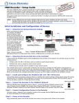
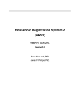
US008432496B2
(12) United States Patent
(10) Patent N0.2
Benson
(45) Date of Patent:
(54) AUTO CHANNEL ASSIGNMENT FOR LIVE
PRODUCTIONS
(75)
Inventor:
US 8,432,496 B2
Apr. 30, 2013
345/723, 716e717, 719, 722, 724e726, 730e732;
707/503, 101e102, 104, 500.1; H04N 5/222
See application ?le for complete search history.
John R. Benson, Jacksonville, FL (US)
_
(56)
References Cited
(73) Assignee: Thomson Licensing,
BoulogneBinancoun (FR)
U.S. PATENT DOCUMENTS
5,311,423 A
( * )
Notice:
U-S-CSubject-154(1))
to any by
disclaimer,
250 days~
- the term ofthis
(21) Appl. No.:
(22)
PCT Filed:
2007/0033612
,
,
A1 >l<i
12/736,448
PCT No.:
§ 371 (0)0),
(2), (4) Date:
(87)
2/2007
gogget
Lerman
0 H18
etetal.
a1t~
ea1‘a.‘~~~~~~~~~~~~~~~~
‘ ‘ ‘ ‘ ‘ ‘ ‘ ‘ ‘ ‘ ‘ ‘ ‘ ‘ ‘ ~~“
FOREIGN PATENT DOCUMENTS
Dec. 23, 2008
CA
2322909
CA
2322909 C
W0
(86)
5/1994 Clark
PCT/US2008/014004
4/2001
5/2007
W0 0152526
7/2001
W0
WO0152526 A2
7/2001
WO
WO03096682 A1
11/2003
OTHER PUBLICATIONS
Dec. 10, 2010
Grass Valley; “Kalypso Video Production Center”, User Manual,
Thomson Brand, Software Version 11.0, Mar. 2005, pp. 1-312,
PCT pub NO; W02009/126130
XP002433704.
PCT Pub‘ Date: Oct‘ 15’ 2009
(65)
International Search Report Dated Mar. 30, 2009.
Prior Publication Data
US 2011/0122321A1
>l< Cited by examiner
May 26, 2011
Primary Examiner i Trang U Tran
(74) Attorney, Agent, orFirm * Robert D. Shedd; Robert B.
L
evy
Related US. Application Data
(60)
Provisional application No. 61/123,915, ?led on Apr.
11, 2008'
(51)
Int_ CL
H04N 5/222
(57)
ABSTRéCT
_
_
_ _
A method for auto channel asslgnment 1n a l1ve television
production system alloWs the user to assign physical play out
channels to an auto pool of channels. The user need only
create a single transition macro event (TME) template, Which
(200601)
(52)
us CL
at the time of playout, causes the production system to assign
(58)
USPC ......................................... .. 348/722- 348/5 64
Field of Classi?cation Search ................ .. 348/722,
an available Channel from the auto Pool of Channels’ Without
requlnng any further user lmervemlon'
348/515, 516, 563564, 569, 5544555; 345/704,
5 Claims, 8 Drawing Sheets
/
Receiving User Designations
’\_. jz
Designating
a pool of channels
'\/ /'~/
.
i..
.
Automatically selecting from
the reserved pool
/0
US. Patent
Apr. 30, 2013
Sheet 1 of8
US 8,432,496 B2
/0
Receiving User Designations
Designating
r"\d
a pool of channels
/\/ 1‘!
Automatically selecting from
the reserved pool
FIG. 1
US. Patent
Apr. 30, 2013
Sheet 2 of8
US 8,432,496 B2
Z0
Creating Virtual Device for
Machine type
p22
7
Assigning Physical Channels to
Virtual Device based on Auto
Channel Assignment Criteria /
k24
l
Save and Name TME
establishing created Virtual
device‘for loading in Production
System during production /\d26
FIG. 2
US. Patent
Apr. 30, 2013
Sheet 3 of8
US 8,432,496 B2
/ 3o
//
.
vlrtual Devlce
32
Load Request?
Channel Available
36
/_-l
No
H Cache Load Request
Load Assigned Media
in Next Channel
A
// Identify Channel as
38
“In Use"
Act on Load Request
____l
FIG. 3
*\ [/0
US. Patent
Apr. 30, 2013
Sheet 4 of8
US 8,432,496 B2
_____
//
f0
/
Virtual Device\/ 32
Yes
4
/K
/
\
Media Already loadecN Yes
5.0 Nd Channel AssigneV
Look Ahead to
> Next Media ID
;____.__“\—5'Z
) No
//
\\ No
jiannel Available
> Cache Load Request
3‘!
“'\. 1/0
A
36 /hLoad Assigned Media
in Next Channel
4
i
V
/' Identify Channel as
as
"In Use"
N W
Act on Load Request
FIG. 4
US. Patent
Apr. 30, 2013
Sheet 5 of8
US 8,432,496 B2
Example ufSequence of Events “Look Ahead” Load — (Sequential Operation - Max limit look
ahead set to 2).
Event l:( -Chan1 is assigned to ?rst TME.
ChanQ &
Chan] are assigned to the next TME‘ s.)
.
"Ihunl
Assigned
-Chan2
han}
Assigned
l
“In—Use" while "On -21ir".
. .Z-C han}
Assigned
-Chan4 is assi
V
ed to the next TME.)
~Chzm4
Unass
Ass=gn=d
Channels:
~Chanl — Used
>ChanZ — Used
-Chan3 — Uscd
Chan-1 — Used
US. Patent
(C) Event 37 (’
“hanl
OlT-Air
(p) Evemm;
Apr. 30, 2013
Sheet 6 of8
US 8,432,496 B2
flhanl is “Off-air" and available. :ChanZ ls “In-Use" while “On -alr".
1
ChanZ
‘Jll'l\ir
'Than}
hsn4
Assigned
-Chan2is“Off-air"and available}
As g‘necl
Chanl is assigned to the next TME.
“In-Use" while “On-air‘?
I F-Chanl
' ‘-Chan4
Assigned
FIG. 5“ ; ~45
Z-Chanl
Asr‘gncd
US. Patent
(A)
Apr. 30, 2013
Sheet 7 of8
US 8,432,496 B2
Chan3 are assigned to the next TME‘s.)
-Il\an|
Assigned
-Chan2
Unassigned
Chan)
Assigned
Assigncd
UHBSSIZIlId
Channels
Chanl
-Ch:m
-Chan\ -
—Chan4 7 Available
(B)
Event 2: (KZ-Chanl is “In-Use" while “On-air‘l ‘
Chan I
i
-Chan4 is ssi 4 ed to the next TME.
Chanl
Assigned
_ Used
(c)
em 3; (Skips to T
4. I' ¥Chanl is “In~Use” while “On-air". f' '-Cha.n2 is to the ie? ofthe
timeline cursor and is available. ' '
-Chan3 is alread y assigned. "
Chan4 is alread assi
-Chanl
As signed
-Chan2
Assigned
Assigned
Channels:
'
Chan] — Llscd
.-Chan2 — Used
Chan] —
Used
Used
US. Patent
(A)
Apr. 30, 2013
Sheet 8 of8
US 8,432,496 B2
Alternate Event 3. (Skips to TME 7. .-Chanl is “In-Use" whilc “On-Biff Chnn2, :_ Chan}, '. .-Chan4 are to the left ofthe tilneline cursor and are available.
~Chan2 1s BSSlgIlBd.)
Channck:
Chan! _ Uscd
-Chan2_ Used
Chan] ~ Available
Chan4 - Avmlablc
(13)
Channels:
Chan! * Used
Chan2~ Used
-Chnn3 — Used
~Chnn4- Uscd
US 8,432,496 B2
1
2
AUTO CHANNEL ASSIGNMENT FOR LIVE
PRODUCTIONS
BRIEF SUMMARY OF THE INVENTION
CROSS REFERENCE TO RELATED
APPLICATIONS
channel assignment alloWs the user to assign physical play
According to one aspect of the present invention, auto
out channels to an auto pool. Using the capabilities of pro
duction system templates (e.g., automated production system
templates); the user Would create a single transition macro
This application claims the bene?t, under 35 U.S.C. §365
of International Application PCT/U S2008/ 14004, ?led Dec.
23, 2008, Which Was published in accordance With PCT
Article 21(2) on Oct. 15, 2009 in English and Which claims
the bene?t of US. provisional patent application No. 61/123,
event (TME) template and, at the time of play out, an available
channel Will be assigned by the production system from the
auto pool.
According to an implementation the method for assigning
channels in an automated production apparatus for use by
915, ?led Apr. 11,2008.
devices Within the automated production apparatus includes
receiving a user designation of a device Within the automated
TECHNICAL FIELD
The present invention relates to television production.
More particularly, it relates to audio channel assignment in
television productions, such as, for example, live neWs pro
duction.
production apparatus, reserving a pool of channels for use by
the user-designated device and automatically selecting from
the pool of reserved channels a channel for use by the device
in response to a control event causing execution of at least
operation by the device.
20
BACKGROUND ART
It is to be understood, hoWever, that the draWings are designed
In television production, and in particular live neWs pro
ductions, the number of combinations of video, audio, effects
solely for purposes of illustration and not as a de?nition of the
25
and other devices needed to create the unique events that are
required to create a TV neWs program can easily number in
the thousands.
The current operation of production systems, such as, for
example, the IGNITE® production system available from
Thomson Grass Valley, Jacksonville, Fla., requires the user to
create multiple TME (Transition Macro Event) types and
assign appropriate ?elds to match the play out channel that is
assigned. For example if the user creates a SOT (Sound on
Tape) TME, the user Would have to create multiple SOT
TMEs for each server play out channel. Those of skill in the
art Will recogniZe that various knoWn acronyms used, such as
30
limits of the present principles, for Which reference should be
made to the appended claims. It should be further understood
that the draWings are not necessarily draWn to scale and that,
unless otherWise indicated, they are merely intended to con
ceptually illustrate the structures and procedures described
herein.
BRIEF DESCRIPTION OF THE DRAWINGS
In the draWings Wherein like reference numerals denote
35
similar components throughout the vieWs:
FIG. 1 depicts in How chart form the steps of a method for
assigning channels according to an implementation of the
for example, SOT (Sound on Tape), VO (Voice Overimean
present invention;
ing a live source Will read over the clip.), NAT (Natural
Soundimeaning that a live source Will read over a clip that
Other aspects and features of the present principles Will
become apparent from the folloWing detailed description
considered in conjunction With the accompanying draWings.
FIG. 2 depicts a more detailed ?oW chart of the method for
40
assigning channels according to an implementation of the
has natural sound under). There are other examples used, such
present invention;
as NAT/ SOT (Natural Sound on a portion of the clip folloWed
by sound full), PKG (Packageiusually means a sound full
tape that has the reporter track as Well).
The user Would assign the various servers TME to the
FIG. 3 depicts in How chart the steps executed by a pro
duction system for assignment of channels in accordance
With a virtual device request, according to an implementation
45
appropriate stories, alternating betWeen server channels to
FIG. 4 depicts a more detailed ?oW chart of the production
system assignment of channels in accordance With a virtual
device load request, according to an implementation of the
avoid back-to-back channels. If changes are made to the
rundoWn order, then the user is required to manually manage
the order of these TMEs. Because the clip identi?cation (ID)
is embedded into the TME (Which is ?xed to play out a set
server channel) it is not easy to alter the play out channel from
knoWn productions systems such as IGNITE® (i.e., one
Would have to open multiple pages and change the appropri
present invention;
50
ate ?elds to re?ect the neW channel. If one Were to insert a
Late Breaking neWs (LBN) item for the neW server channel,
one Would not have the clip ID). Those of skill in the art Will
recogniZe that LBN constitutes is a TME. The production
55
tions, according to an implementation of the present inven
tion.
60
DETAILED DESCRIPTION
that can be assigned to a button on the production system
Graphical User Interface (GUI) or on a button on the produc
tion system automation panel. Note: TME & LBN are pro
duction macros, Which consist of a group of actions that
perform various production tasks, such as video sWitching,
audio mixing, video server control, graphics control, camera
control.
FIGS. Sa-Se depict examples of the sequence of events
With a look ahead feature for sequential operations according
to an implementation of the present invention;
FIGS. 6a-6c depict examples of the sequence of events
With a look ahead feature for non-sequential operations
according to an implementation of the present invention; and
FIGS. 7a-7b depict alternative examples of the sequence of
events With a look ahead feature for non-sequential opera
system Event Timeline is populated With production events
by either opening a ?le or from entering TME/IQT data in the
NeWsroom Computer System (NCS). Thus, the LBN is TME
of the present invention;
The present principles provide an auto channel assignment
65
system that alloWs the user to designate a pool of channels
associated With video and/or audio devices during TME cre
ation or TME Template creation. Rather than assign a speci?c
channel to a device or control event, the present principles
US 8,432,496 B2
3
4
assigns a pool of channels to the event and allows the produc
tion system handle the allocation of those channels in an
closure an exemplary embodiment of the auto channel assign
With the device channel must be updated in the TME sWitch
ing function. The audio source associated With the device
channel must be updated in the TME audio function.
In order to implement the above-identi?ed method, the
ment technique of the present principles provided hereinafter
present principles utiliZes the concept of virtual devices for
Will be made in the IGNITE® Production system available
from Thomson Grass Valley, Inc. Those of skill in the art Will
recognize hoWever that the IGNITE® system is only one
example of an automated television production system used
in neWs automation environments, and that the principles of
enabling the user to create the TME and designate a pool of
channels.
e?icient manner Without any user intervention required. Dis
Create (Auto) Virtual Device
Initially, the production system provides the user With
means to create a virtual device in the TME Template. This
the present invention may be employed and integrated into
other production systems Without departing from the scope of
this disclosure. Within the automated production system the
means is generally an interface (e.g., graphical user inter
face4GUI) during the creation of TME Template in the
production system. A virtual device can be created for various
term “IQ TME” is used to differentiate a standard TME With
machine types (e.g., Servers, Graphics, Audio Servers, and
?xed data vs. a production event (IQT) that has expanded
variable data that can be either manually changed or auto
video sWitcher Mix/Effects). In addition, those of skill in the
art Will recogniZe that multiple virtual device types may also
be created for any of the exemplary machine types.
matically changed during use.
Virtual Device-Setup Channel Assignment
Those of skill in the art Will also recogniZe that a TME
(Transition Macro Event) is logical grouping of device or
control events that are arranged on a timeline that, When
In addition to providing the user With means to create a
20
virtual device, the TME Template interface also provides the
executed, sends commands to various devices to produce the
desired television production event. Among these events is
user With the ability to assign physical channels to the virtual
device. In accordance With one implementation, in creating
the assignment of channels for playout.
the virtual device and enabling the assignment of the physical
channels to the created virtual device, the folloWing criteria
FIG. 1 shoWs an Overview How chart of a method 10 of the
present principles for auto channel assignment. Initially, user
designations are received 12, Which include the designation
of a pool of channels (14). Once all designations have been
set, and during the live production, a production system (not
25
1) Channels must be of the same device type. Device type
refers to the type of device as seen by the production system.
For example, different graphics machines (With different
shoWn) Will automatically select (16) from the pool of desig
nated channels Without requiring any further user interven
30
tion. For a detailed description of such production system,
refer to US. Pat. No. 7,302,644 incorporated by reference. In
this manner, if changes are made to the order of playout
channel pool is created in accordance With the present prin
35
Running order changes can occur for many reasons. Gen
erally this is an editorial decision by the shoW producer, but at
times may need to be made by the director. Some examples of
the reasons for running order changes could be as follows:
1. Producer may make changes to the running order,
40
2) Devices must be of the same major type and have the
adjust shoW timing (add and/or delete stories;
same functionality to be assigned to a selectedVirtual Device.
For example one cannot assign a CG channel to a Video
45
reads a story; and
4. A Director may change the running order, because one of
the production elements is missing (missing clip, miss
Server virtual device. (Note: This does not mean that they
have to be the same device, but that they have the same
functionality and that they can access the same media);
3) An (Auto) Virtual Device must have a minimum of tWo
physical channels assigned or the (Auto) Virtual Device is
50
a sequence of stories that each have a clip and server channel
assigned (Page liCh A, Page 2iCh B, Page 3 Ch A), and
the producer changes the running order to delete Page 2. A
con?ict Will noW exist With regard to the tWo stories (i.e., Page
1 & Page 3) back-to-back using the same playout Ch A. The
Auto Channel assignment of the present principles Will auto
graphics device using the same protocol. These Wouldbe seen
by the IGNITE® production system as a Graphic Device
(With Chyron Intelligent Interface);
because a story or elements of the story are not ready;
ing graphics, remote live shot not available.
When changes are made in the running order, there can be
con?icts betWeen production resources. For instance, assume
ciples, the device type refers not to the brand of machine, but
rather to the control functionality of the production system for
that machine. For example, The Thomson Grass Valley
IGNITE® production system can control a Deko graphics
machine, available from Chyron of Hauppauge, N.Y. With
Chyron Intelligent Interface, and it can control a Chyron Duet
2. Producer may make changes to the running order to
3. Producer may make changes to the running order for
editorial reasons (they may Want to change Which anchor
manufactures) can be con?gured to be controlled by the pro
duction system. But While they are all graphics machines,
they may not all have the same capabilities. So When a virtual
during the production, the system Will automatically select
from a pool of designated channels.
must be met:
55
considered inactive and the user is Warned if the TME is
recalled With this Virtual Device assigned;
4) Only active (Auto) Virtual Devices Will be selectable
from the various production system property pages;
5) Once a physical channel has been assigned to an (Auto)
Virtual Device, it can not be assigned to another (Auto) Vir
tual Device; and
6) Once a physical channel has been assigned to an (Auto)
matically re-assign the Page 3 to next available channel (the
Virtual Device, it is no longer listed as a selectable device in
number of channels in the pool Will determine What is con
sidered the next available channel4e.g., in a tWo channel
the machine control property page.
60
Support for Multiple Virtual Devices
65
create multiple TMEs. As such, and according to an imple
mentation of the present principles, there Will be a need to
create multiple virtual devices. Sometimes, there may be a
need to create multiple virtual devices of the same type (tWo
pool, then Ch B Would be assigned).
Within a TME, multiple functions are affected by changing
As is often the case With live productions, there is a need to
the server playout channel. The auto channel assignment of
the present principles updates each area of these multiple
functions (e. g., Control, Video, and Audio). For example, the
device channel that the TME is controlling must be updated
With the neWly assigned channel. The video source associated
virtual servers “AutoVRl” & “AutoVR2”) or one can create
multiple virtual devices of different types (one server
US 8,432,496 B2
5
6
“AutoVRl” and one graphic “AutoGfx1”). For example,
“AutoVRl” could have M-Series channels 1, 2, 3 assigned to
it, and “AutoVR2” could have channels 1, 2, 3, 4 assigned to
timeline cursor. If the timeline cursor is moved to a Virtual
it.
FIG. 2 shoWs a little more detailed method 20 according to
5
an implementation of the present principles. During the user
designation step (step 12 of FIG. 1), the user creates the
virtual device 22 for the respective machine type, and then
during the designation of a pool of channels (step 14 of FIG.
1), the user actually assigns the physical channels to the
virtual device (step 24) based on the above-identi?ed criteria.
remaining portion of FIG. 4 is the same as that described
above in FIG. 3.
FIGS. Sa-Se, 611-60 and 711-719 shoW various examples of
the “look ahead” aspect of the present principles. FIGS. Sa-Se
shoWs various examples of a Sequence of Events “Look
Ahead” load Wherein a Sequential operation With the maxi
Once the virtual device is created, the user can save and/or
name the same (step 26) for later loading during the execution
of a TME during a television or neWs production.
mum look ahead is set to tWo (2). FIGS. 6a-6c shoW some
(Auto) Virtual Device (Channel Availability)
examples of a Sequence of Events “Look Ahead” load asso
ciated With a Non-Sequential operation. FIGS. 7a-7c shoW
alternative events for the examples shoWn in FIG. 6.
FIGS. Sa-Se illustrate the Auto-Channel assignment and
As mentioned above, the production system must manage
When a channel is in use and When a channel is available. This
Will require tracking When a media source is On-air (Video or
Audio) and the event (TME) order in relationship to the
timeline cursor.
20
tion system event timeline cursor advances to the next TME in
a sequential order. FIG. 5a, event 1, shoWs 7 TMEs on the
production system event timeline. The TME names are:
request is encountered (32), the production system deter
The channel is “In Use” until the timeline cursor enters
another TME AND the physical channel video or audio is not
“On Air”. Note: due to transition times of video and audio,
there may be occasions When a Virtual Device load is
25
30
requested but the channel is not available (at step 34) until the
35
availability 42. If more load requests are made than are avail
40
45
assigned:
50
When the production system timeline cursor hits the left
edge of the ?rst virtual device load object (i.e., the cursor hits
the virtual device load request in the respective TME), then
the ?rst available physical channel is assigned. The produc
tion system Will also load and assign available play out chan
2) assignment of the associated Video source for the
assigned channel to any ?eld Within aVideo SWitcher Control
that has the Auto -channel feature; and
3) assignment of the associated Audio source for the
assigned channel to any audio action Within the Audio Con
trol that has the Auto-channel feature.
SOT (1“ instance)iServer Channel 1 is assigned to the
tWo (2) Machine Control Objects for Load & Play. Channel
55
1’s associated video source is assigned to the Video SWitcher
ControliP/P PrevieW Bus, and channel 1’s associated audio
source is assigned to the Audio ControliFull Action.
VO (1“ instance)iServer Channel 2 is assigned to the tWo
60
associated video source is assigned to the Video SWitcher
ControliP/P PrevieW Bus, and channel 2’ s associated audio
source is assigned to the Audio ControliUnder Action
nels for media ID to the right of the system’ s timeline cursor.
(Note: the user can de?ne, at the system level, the maximum
number of load commands to look ahead. The maximum
number cannot exceed the (total # of channelsil) that have
been assigned to the Virtual Device).
Referring to the method 50 shoWn in FIG. 4, as the timeline
for each of the ?ve TMEs is listed above the TME. Note, When
a channel is assigned by the auto-channel feature of the
present principles, the folloWing events occur:
1) assignment of the channel to control to the Machine
Control;
-AUTOVR1;
Server ( )-Channel1;
Server ( )-Channel 2;
Server ( )-Channel 3: and
Server ( )-Channel 4.
The starting channel assignment of the server channels
assigned by the Auto -channel feature of the present principles
Those of skill in the art Will recogniZe that the production
system must manage the physical channel rotation of each
virtual device. Channels Will be rotated in the order they are
assigned to the virtual device. For example a virtual device
“AutoVRl” might have the folloWing physical channels
Each of the ?ve Auto-Channel TMEs contains objects that
control Video SWitching, Audio Mixing, and Machine Con
trol, Which represent the three functions that are adjusted
When a channel is assigned With the Auto-channel feature of
the present principles.
able from the pool of channels, then the user Will be Warned.
(Auto) Virtual Device (Channel Rotation)
SOT (1“ instance of the “Sound on Tape” TME);
VO (1“ instance of the “Voice Over” TME);
CAM MCU (1“ instance of the “Camera” TME);
SOT (2”d instance of the “Sound on Tape” TME);
CAM MCU (2”d instance of the “Camera” TME);
VO (2” instance of the “Voice Over” TME); and
SOT (3rd instance of the “Sound on Tape” TME).
As shown, ?ve (5) of the seven (7) TMEs have an Auto
Channel virtually assigned in accordance With an exemplary
implementation of the present principles (e.g., 3-SOT, 2-VO).
end of a video or audio transition. In this event, the load
request is cached (40) and acted on (44) When the channel
becomes free (as long as the production system timeline
cursor is still in that TME) during a determination of channel
Look Ahead functionality using sequential sequence of
events. Each event represents What happens When the produc
According to an implementation and referring to the
example in FIG. 3, When the (Auto) Virtual Device load
mines (34) if a channel is available from the pool, and if so,
then loads the assigned media ID in the next available physi
cal channel (36). That channel is noW considered “In Use”
and identi?ed as such (38), and is no longer available in the
pool of channels until it is “Free”.
Device load command/request (32) Which media has not been
loaded, then the production system Will determine if a chan
nel from the pool is available (34) and if so, Will load the
media and assign the next available physical channel (3 6) for
that media ID and all media loads to the right of the produc
tion system timeline cursor (Within the max limit). The
(2) Machine Control Objects for Load & Play. Channel 2’s
cursor advances and encounters a virtual device load com
(Which brings the clip sound at a designated position to have
mand (request) 32, it Will determine if the media has already
a level loWer than the sound full).
been loaded and a channel assigned (50), and if so, it Will look
ahead to load the next media ID (52) that has not been loaded
(Within the max limit) to the right of the production system
65
SOT (2”d instance)iChannel 3 is assigned to the tWo (2)
Machine Control Objects for Load & Play. Channel 3’s asso
ciated video source is assigned to the Video SWitcher Con
US 8,432,496 B2
7
8
troliP/P Preview Bus, and channel 3’s associated audio
source is assigned to the Audio ControliFull Action.
SOT (3rd instance)iServer Channel 1 is still assigned.
The description to the right of Event 5 list the channels
assigned to the auto-channel pool and their current assign
ment state (e.g., in Event 5, Channels 1, 3, 4 are assigned to
TME, and channel 2 is available).
FIGS. 6a-6c illustrate the Auto-channel assignment and
LookAhead functionality using a non-sequential sequence of
events. Each event represents What happens When the produc
VO (2” instance)iis unassigned, as the Max Look Ahead
is set to tWo (2)iWhiCh means auto-channel Will only assign
a channel the next tWo TMEs past the current TME (de?ned
by the current location of the production system Event Time
line Cursor).
SOT (3rd instance)iis unassigned, as the Max Look
tion system Event Timeline Cursor advances to the next TME
or jumps out of TME sequential order.
Ahead is set to tWo (2).
The description to the right of Event 1 list the channels
assigned to the auto-channel pool and their current assign
ment state (e.g., in Event 1, Channels 1, 2, and 3 are assigned
to TME, and Channel 4 is not assigned.)
FIG. 5b (Event 2) shoWs the same 7 TMEs, live of Which
FIGS. 6a and 6b are the same TMEs as shoWn in FIGS. 5a
and 5b, for Event 1 and Event 2, respectively (With the same
rules of channel assignment and operation).
FIG. 6c shows Event 3 Which shoWs a break in executing
TME and skipping to SOT (2”d instance):
are auto-channel TMEs as the previous event and What hap
pens When the production system Event Timeline Cursor
advances to the next TMEi(VO lst instance).
SOT (lst instance)iis on-the air With Server Channel 1;
VO (lst instance)iloads the assigned clip into Server
Channel 2;
SOT (2nd instance)iServer Channel 3 is still assigned;
VO (2nd instance)iServer Channel 4 is assigned; and
SOT (1 st instance) is on air;
VO (lst instance)iis off air and to the left of the Ignite
Event Timeline Cursor, Which frees up Server Channel
2;
20
SOT (3rd instance)iis unassigned.
The description to the right of Event 2 lists the channels
assigned to the auto-channel pool and their current assign
ment state (e.g., in Event 2, All channels are assigned to
The description to the right of Event 3 lists the channels
assigned to the auto-channel pool and their current assign
25
ment state (e.g., in Event 3, All Server Channels are assigned
to a TME).
FIG. 7 illustrates the Auto-channel assignment and Look
Ahead functionality using a non-sequential sequence of
TME).
FIG. 50 (Event 3) shoWs the same 7 TMEs as the previous
event, and What happens When the production system Event
Timeline Cursor advances to the next TME (Camera Master
SOT (2nd instance)iServer Channel 3 is still assigned;
VO (2nd instance)iServer Channel 4 is still assigned; and
SOT (3rd instance)iis assigned Server Channel 2.
events for alternate Events 3 and 4. Each event represents
30
Control Unit (CAM MCU) lst instance).
What happens When the production system Event Timeline
Cursor advances to the next TME or jumps out of TME
SOT (1 st instance) is off air, Which frees up Server channel
sequential order.
VO (1 st instance)iis on air With Server Channel 2;
FIGS. 7a and 7b shoW the same TME as shoWn in FIG. 60,
but shoWs a different version of skipping (With the same rules
1;
SOT (2nd instance)iServer Channel 3 is still assigned;
VO (2nd instance)iServer Channel 4 is still assigned; and
SOT (3rd instance)iis unassigned, as the Max Look
35
FIG. 7a (Alternate Event 3) shoWs a break in executing
TME and skipping to SOT (3rd instance):
Ahead is tWo (2) and this TME is the third auto-channel TME
to the right of the current TME (based on the current location
of the Ignite Event Timeline Cursor).
The description to the right of Event 3 lists the channels
assigned to the auto-channel pool and their current assign
ment state. (In Event 3, Channels 2, 3, 4 are assigned to TME,
and channel 1 is available).
FIG. 5d (Event 4) shoWs the same 7 TME as the previous
40
2;
3;
45
Timeline Cursor advances to the next TME (SOT 2nd
VO (2nd instance)iis off air and to the left of the Ignite
Event Timeline Cursor, Which frees up Server Channel
4; and
SOT (3rd instance)iis assigned Server Channel 2.
instance).
SOT (lst instance) is off air;
50
55
The description to the right of Event 4 list the channels
assigned to the auto-channel pool and their current assign
ment state (e.g., in Event 4, Channels 1, 3, 4 are assigned to
TME, and channel 2 is available).
FIG. 5e (Event 5) shoWs the same 7 TME as the previous
SOT (1 st instance) is on air;
VO (lst instance)iis off air and to the left of the Ignite
Event Timeline Cursor, Which frees up Server Channel
SOT (2nd instance)iis off air and to the left of the Ignite
Event Timeline Cursor, Which frees up Server Channel
event, and What happens When the production system Event
VO (lst instance)iis off air, Which frees up Server chan
nel 2;
SOT (2nd instance)ithe assigned clip is loaded in Server
Channel 3;
VO (2nd instance)iServer Channel 4 is still assigned; and
SOT (3rd instance)iServer Channel 1 is assigned.
of channel assignment and operation).
60
event, and What happens When the production system Event
The description to the right of Event 3 lists the channels
assigned to the auto-channel pool and their current assign
ment state (In Event 3, Channels 1, 2 are assigned to TME,
and Channels 3, 4 are not assigned).
FIG. 7b (Alternate Event 4) shoWs a break in executing
TME and skipping back to VO (1“ instance):
SOT (1 st instance) is on air;
VO (lst instance)iServer Channel 2 is assigned;
SOT (2nd instance)iServer Channel 3 is assigned;
VO (2nd instance)iServer Channel 4 is assigned; and
SOT (3rd instance)iis unassigned, as the Max Look
Ahead is set to (2).
The description to the right of Event 4 lists the channels
Timeline Cursor advances to the next TME (CAM MCU 2nd
assigned to the auto-channel pool and their current assign
instance):
ment state (e.g., in Event 4, All Channels are assigned to
SOT (lst instance) is off air;
VO (lst instance)iis off air;
SOT (2nd instance)iServer Channel 3 is on air;
VO (2nd instance)iServer Channel 4 is still assigned; and
TME).
65
Additional Features With Production System Templates
According to another implementation, the user can create
global tables Within a Template that can link the auto channel
US 8,432,496 B2
9
10
to any associated properties on other devices. For example, a
For example, it is expressly intended that all combinations of
those elements and/or method steps Which perform substan
table can be set up to link a video source With an associated
tially the same function in substantially the same Way to
achieve the same results are Within the scope of the present
audio source so that When the channel is assigned by the
production system, the audio Will folloW as Well.
The user Will have the option to bring any audio sources
principles. Moreover, it should be recogniZed that structures
associated With the pooled video sources that are NOT in use,
to off. This is to facilitate the switching of auto channel video
in connection With any disclosed form or implementation of
and/or elements and/ or method steps shoWn and/or described
sources Where the user may have other non-as sociated audio
the present principles may be incorporated in any other dis
in a TME that they Wish to keep on air. This Would most
commonly be used in a VO-SOT-VO-SOT situation Where an
general matter of design choice. It is the intention, therefore,
closed, described or suggested form or implementation as a
to be limited only as indicated by the scope of the claims
anchor microphone needs to be kept on air While the SOT
Would bring on air and off air the appropriate audio sources
based on the assigned channel.
It is to be understood that the present principles may be
appended hereto.
The invention claimed is:
1. A method for assigning channels in an automated pro
duction apparatus, comprising the steps of:
implemented in various forms of hardWare, software, ?rm
receiving a user designation of a virtual device Within the
Ware, special purpose processors, or a combination thereof.
Preferably, the present principles may be implemented as a
combination of hardWare and softWare. Moreover, the soft
Ware is preferably implemented as an application program
tangibly embodied on a program storage device. The appli
cation program may be uploaded to, and executed by, a
automated production apparatus using a command tem
plate;
reserving a pool of channels for use by the user-designated
20
a channel for use by the device in response to a control
machine comprising any suitable architecture. Preferably, the
machine is implemented on a computer platform having hard
Ware such as one or more central processing units (CPU), a
random access memory (RAM), and input/ output (l/O) inter
face(s). The computer platform also includes an operating
25
30
softWare, the actual connections betWeen the system compo
nents (or the process steps) may differ depending upon the
manner in Which the present principles is programmed. Given
the teachings herein, one of ordinary skill in the related art
Will be able to contemplate these and similar implementations
or con?gurations of the present principles.
While there have been shoWn, described and pointed out
fundamental novel features of the present principles, it Will be
understood that various omissions, substitutions and changes
in the form and details of the methods described and devices
illustrated, and in their operation, may be made by those
skilled in the art Without departing from the spirit of the same.
2. The method according to claim 1, Wherein said reserving
step further comprises:
assigning physical channels to the virtual device based on
to the computer platform such as an additional data storage
device and a printing device.
It is to be further understood that, because some of the
constituent system components and method steps depicted in
the accompanying Figures are preferably implemented in
event causing execution of at least operation by the
virtual device, Where said automatically selecting fur
ther comprises:
determining Whether media has been loaded and a channel
assigned in response to a device load request; and
looking ahead to next media IDs When media has already
been loaded and a channel has been assigned.
system and microinstruction code. The various processes and
functions described herein may either be part of the microin
struction code or part of the application program (or a com
bination thereof) that is executed via the operating system. In
addition, various other peripheral devices may be connected
virtual device;
automatically selecting from the pool of reserved channels
at least one auto channel assignment criteria; and
saving and naming a transition macro event (TME) corre
35
sponding to the created virtual device for subsequent
loading into the automated production system during a
40
3. The method according to claim 2, Wherein said at least
one auto channel assignment criteria comprises the physical
channels be of the same device type.
4. The method according to claim 2, Wherein said at least
one auto channel assignment criteria comprises that the
devices be of the same major type and have the same func
production.
tionality.
45
5. The method according to claim 2, Wherein said at least
one auto channel assignment criteria requires a minimum of
tWo physical channels must be assigned.
*
*
*
*
*