1
SNET to USB Interface 35954U User Manual
Version: 1.3.0.0
Page 1 of 98
Technical Specifications 3595 4U IMP Interface
Inputs:
Power requirement: 24-48Vdc External Power Supply
Power connection: Panel mounted 9 pin D sub plug
Outputs:
Output: SNET IMP power supply - serial communication network.
Output connection: Panel mounted 9 pin D sub socket.
Panel mounted USB "B" connection
Network Cable Details:
Cable Spec: Screened single pair cable 100Ohm impedance. 12-24AWG depending on network
length and number of IMPs
Maximum No IMPs: 50
Operating Conditions :
Temperature range: -20 to +50C
Relative humidity:(0 to 40C) <90%
Mechanical:
Casing: Aluminium sealed to IP55
Size (w x d x h) 170 x 116 x 36mm
Weight: 2kg
Accessories:
•USB Cable
•SNET network terminator on interface unit
•24-48VDC power supply (not included)
Page 2 of 98
1. Part 1
1.1. Chapter 1- Introduction to 35954U Interface
1.1.1.
THE INTERFACE
The 35954U Interface is operable with any host computer that is fitted with a USB compatible
interface. The Interface allows the host to communicate with a maximum of 50 IMPs via an S-Net
cable.
The Interface provides all the hardware, timing control, error checking and data protocol necessary for
reliable communication between the host computer and the S-Net system.
1.1.1.1.
The 35954U Interface
Page 3 of 98
1.1.1.2.
Front Panel
1.1.1.3.
Rear Panel
Page 4 of 98
1.1.2.
THE MANUAL
This manual explains how to install and operate the 35954U Interface.
Part 1 of the manual relates to the Interface itself:
Chapter 1
Introduces the various facilities of the 35954U Interface
Chapter 2
Relates to the installation of the 35954U Interface. Explains how to:
•
Connect the Interface to IMPs, via S-Net,
•
S-Net Termination
•
Connect up an external power supply
•
Connect to a PC
Chapter 3
Details the cabling and power supplies required for your particular system
Chapter 4
Describes the syntax, function and response of each of the Interface commands. The
commands relate specifically to the 35954u Interface.
Part 2 of the manual contains details of the IMP commands and responses.
Chapter 1
Describes the syntax, function and response of each of the IMP commands.
Chapter 2
Describes the format of the results and error messages received from the IMPs.
Page 5 of 98
1.1.3.
DATA STREAMS
To categorise data the S-Net protocol operates four separate data types called streams. Each stream
uses a different data format. This allows an application program to attach different priorities to data
types and so to improve the speed with which high priority data (such as event timing) is handled. The
steams are arranged as follows:
Stream 0
Data in response to a command to measure all channels (a scan) or long numeric
responses.
Stream 1
Data in response to a command to measure one channel or short numeric responses.
Stream 2
Event information.
Stream 3
Character (ASCII) data, in response to some commands (status information or
confirmations etc.).
1.1.4.
INTERFACE AND IMP COMMANDS
Commands are used in the form of ASCII character strings. For example, the RESET command is
RE.
A command may be made more specific by using it with a number. For example, the command CL2
means ‘clear event totalize counter on channel 2’. Multiple commands may be sent in strings to IMPs.
They must be separated by semicolons. For example:
ST;CL2
A directory of Interface commands is presented in Part 1, Chapter 4, and a directory of IMP
commands is given in Part 2, Chapter 1 of this manual.
Page 6 of 98
1.2. Chapter 2 – Interface Installation
This chapter outlines the installation of the 35954U Interface. It details how to:
•
Connect the Interface to IMPs, via S-Net
•
S-Net Termination
•
Connect an external power supply
•
Connect to a PC
1.2.1.
CONNECTING THE INTERFACE TO IMPS VIA S-NET
The 35954U Interface unit is connected to the S-Net via a 9-way female ‘D’ type connector on the rear
panel of the unit (labeled ‘S-Net’). The connections to this are listed in Table 1.1 below.
1.2.1.1.
Table 1.1 S-Net Connections
Pin
1,2,6
3,4,5
7,8,9
1.2.2.
Function
Screen
SNET+
SNET-
S-NET TERMINATION
The IMPs, and S-Net Interface within the 35954U Interface, are high impedance devices, whilst the SNet cable which interconnects them has a characteristic impedance of approximately 100Ω.
Therefore, to avoid signal reflections, the S-Net cable must be correctly terminated at both ends.
The way in which the S-Net cable is terminated depends on where the 35954U Interface is placed in
the S-Net system. An S-Net terminator is fitted in the Interface. A pair of terminators for use on the
IMPs are supplied with the 35954U Interface.
Where the interface is placed at one end of the network (Fig 1.2) the terminator in the IMP Interface
must be connected. A terminator should also be fitted to the IMP at the other end of the network.
Page 7 of 98
1.2.2.1.
Figure 1.1: The 35954U Interface placed at end of S-Net
IMP
1
CONTROLLER
IMP
2
IMP
3
IMP
4
IMP Interface Unit
USB
*
To fu r th er I MPs fi re quir ed *
S-Net
To further IMPs if required
*S-Net terminators should be fitted to the IMP
Interface and to the IMP at the end of the S-Net
Where the Interface is placed in the network (Fig. 1.2) the terminator in the 35954U Interface should
be disconnected and the IMPs at either end of the network should each have a terminator fitted.
1.2.2.2.
Figure 1.2: The 35954U Interface placed between IMPs on the S-Net
CONTROLLER
IMP Interface Unit
USB
IMP
1
IMP
2
IMP
4
IMP
3
IMP
5
IMP
6
IMP
7
S-Net
To fu rt her IM sP i f r equ ri ed *
To fu rt her IM Ps i f r equ ri ed *
To further IMPs if required
To further IMPs if required
*S-Net terminators should be fitted to the IMPs at
either end of the S-Net cable
Page 8 of 98
1.2.2.3.
1.2.2.1 INSERTING OR REMOVING THE TERMINATOR JUMPER
The S-Net terminator within the 35954U Interface Unit is connected via an internal jumper. To
disconnect the terminator you simply remove the jumper. The configurations which decide whether or
not the terminator is to be connected are described on the previous page. The procedure for
accessing the terminator jumper is as follows.
1. Remove and retain the 4 screws from the rear panel (where the S-Net and Power Connections
are located) of the Interface.
2. With care, slowly slide out the panel. You do not need to remove the panel from the housing
completely.
3. In the top right hand corner you will see the jumper (See Fig. 1.3 for assistance). To remove the
jumper, simply lift it out of the PCB. The jumper should be retained for future use. To reinsert the
jumper, push it firmly into the PCB.
4. Slide the panel back into the housing unit and with care, secure the 4 screws.
Figure 1.3: Location of the terminator jumper on the main PCB of the 35954U Interface
Power
S-Net
Terminator Jumper
1.2.3.
CONNECT EXTERNAL POWER SUPPLY
Where the power is supplied to the IMPs down the S-Net cable, this power is generated by an
external supply. The external power supply is connected via a 9-way ‘D’ Type connector located at the
rear of the unit. The connections to this are located in Table 1.2
1.2.3.1.
Table 1.2 External Power Connections
Pin
1-5
6-9
Function
GND
+24 to 48V
Page 9 of 98
The cable requirements for S-Net power, for either the internal or external power supply, are detailed
in Chapter 3 as are the requirements for the external supply.
1.2.4.
CONNECT TO A PC
The 35954U Interface connects to a PC via a USB “B “cable. To install the Interface on your machine,
follow the steps below for the appropriate operating system.
1.2.4.1.
Windows XP
If you are installing the Interface for operation on Windows XP you will need to download and install
the appropriate virtual COM port drivers. These drivers are available from www.solartron-imp.com, or
from http://www.ftdichip.com/Drivers/VCP.htm.
When you have downloaded the drivers, please follow the steps below.
1. Ensure the 35954U Interface Unit is placed securely.
2. Download the virtual COM port drivers save it where you can access it easily
3. Connect the Interface to your machine using a USB “B” cable
4. When prompted, choose to install the drivers manually
5. Navigate to the folder you downloaded in Step 2 and click ok.
6. The drivers for the Interface will now be installed.
7. Once completed you should now see the Interface appear in your device manager under “Ports”
1.2.4.2.
Windows Vista
1. Ensure the 35954U Interface Unit is placed securely.
2. Connect the Interface to your machine using a USB “B” cable
3. Windows Vista should automatically detect and install the drivers for the Interface. If not,
please download the driver from our site, choose manual install, navigate to the downloaded
file and click ok.
4. The drivers for the Interface will now be installed.
5. Once completed you should now see the Interface appear in your device manager under
“Ports”
Page 10 of 98
1.2.4.3.
Windows 7
1. Ensure the 35954U Interface Unit is placed securely.
2. Connect the Interface to your machine using a USB “B” cable
3. Windows 7 should automatically detect and install the drivers for the Interface. If not, please
download the driver from our site, choose manual install, navigate to the downloaded file and
click ok.
4. The drivers for the Interface will now be installed.
5. Once completed you should now see the Interface appear in your device manager under
“Ports”
Page 11 of 98
1.3. Chapter 3 – Cabling and Power Supplies
1.3.1.
S-NET CABLE
IMPs are linked to the 35954U Interface by S-Net, a serial communications network. The S-Net cable
consists of a twisted par of multi-stranded wires with a screen around them and has a nominal
characteristic impedance of 100Ω. Unscreened cables may be used, but in electrically hostile
environments S-Net signals may be subject to interference. In most applications signals and IMP
power a both delivered via the S-Net cable, which is connected to a D-type connector on the
Interface. The connection details are given in Chapter 3.
Table 1.1 lists the cables selected as being particularly suitable for liking IMPs to the Interface. The
cables are intended for general purpose use.
Table 1.1: Cables recommended for S-Net
Gage
(single
conductor)
AWG
12
14*
16
18*
20
24
Type
Brand-Rex T12459
Brand-Rex CD8920204
Brand-Rex T12460, Alpha 9820, Belden 9860
Brand-Rex CD8920251, Belden 9250
Brand-Rex BC57207, Alpha 9818, Belden 9207, Belden 9815 (direct burial)
Brand- Rex BI56641, Alpha 2400, Belden 8641
* The large diameter of these cables necessitates special consideration when making connections to the IMP.
For details see the IMP Installation Guide.
Approximately 10 meters of 24 AWG Belden 8641 cable are provided with each module. This is
sufficient for small data acquisition systems or for testing purposes. The connections are: S-NET + ve
= black and S-Net – ve = white.
1.3.2.
POWER SUPPLY
Each IMP consumes approximately 1W (1.2W at power-up). (35951D Analogue output IMPs can, in
some applications, require more. In these circumstances they need special consideration, refer to the
3595 Series IMP Installation Guide for details.)
IMPs may be supplied with power in one of two ways:
1. From an external 24V-50V dc power supply connected to the external power plug on the Interface
via the S-Net cable. The location and the pin numbering of this external power plug are shown in
Chapter 3, “Electrical Installation of the 35954U Interface”. This method allows up to 50 IMPs to
be operated with a maximum cable length of 1km. See Section 1.3.3.2 “Cable Selection When
Using the Interface External Supply”.
2. Directly from a power supply local to the IMP(s). For further information refer to the 3595 or 3596
Series IMP Installation Guides
Page 12 of 98
1.3.2.1 EXTERNAL POWER SUPPLY REQUIREMENTS
Operation is automatically switched to the external supply when a voltage over 43V is applied to the
external power plug on the Interface.
An external power source must fulfil the following requirements:
(a) Current limited to 3A-4A, or protected by a 4A fuse.
(b) Voltage 43V-50V. This depends on the wire gage, the cable length and the number of IMPs
connected to the cable.
(c) Supply ripple less than 100m V rms.
It is permissible for a battery operated S-Net system to have a charger permanently connected.
Batteries generally provide sufficient output smoothing.
It is important that external power supply is able to supply maximum current on short circuit without
folding back. Foldback is performed by the 35954U unit itself.
1.3.3.
CABLE SELECTION
Cable selection depends on two cable characteristics:
1. The a.c. attenuation of the cable. This affects the digital communications running back and forth
along the cable, between the IMPs and the Interface. There are two specific points to consider:
(a) The high a.c. attenuation of the 24 AWG cable means that S-Nets using this cable cannot be
longer than 660 meters.
(b) The low a.c. attenuation of the 14 and 18 AWG cables means that the S-Nets using these
cables cane be extended up to 1.5km. The large diameter of these cables necessitates
special consideration when making connections to the IMP. For details see the IMP
Installation Guide.
2. The d.c. resistance of the cable. This, and the voltage of the power supply, determines the
maximum number of IMPs that can be powered via the cable. Generally, if any IMPs on the
network are powered from the Interface via the S-Net cable, it is important that a cable of
adequate gage is used. The optimum cable size depends on the number of IMPs to be powered
via the S-Net cable, the cable length required and the power supply voltage. Information on
choosing the cable, either for power provided internally from the interface or from an external
supply via the Interface, is given below.
Page 13 of 98
Table 1.1: Maximum Cable Lengths for IMPs Using the Interface Internal Supply
No. of
IMPS
1
2
3
4
5
6
7
8
9
10
11
12
13
14
15
16
17
18
19
20
21
22
23
24
25
12 AWG
2
(3.4mm )
1000
1000
1000
1000
1000
1000
1000
1000
1000
1000
1000
1000
1000
1000
1000
1000
1000
1000
1000
1000
933
755
577
400
222
Maximum Cable Length (Metres)
16 AWG
20 AWG
2
2
(1.3mm )
(0.5mm )
1000
1000
1000
1000
1000
1000
1000
1000
1000
1000
1000
900
1000
772
1000
675
1000
600
1000
540
1000
491
1000
450
1000
415
1000
384
923
352
841
321
758
290
676
258
594
227
512
196
430
164
348
133
266
101
184
70
102
39
24 AWG
2
(0.2mm )
660
660
660
534
427
356
305
267
237
213
194
178
164
151
139
127
114
102
89
77
65
52
40
27
15
1.3.3.2 CABLE SELECTION WHEN USING THE INTERFACE EXTERNAL SUPPLY
When IMPs are powered from an external supply connected to the Interface it is possible to use
longer lengths of S-Net cable than those listed in Table 4.2/ It is important, however, that the core of
the cable is of an adequate gage. The actual gage required depends on the number of IMPs to be
powered, their distribution along the cable and the power supply voltage.
To select a suitable wire gage and supply voltage for a given system, refer to the cable selection
graph (Fig. 4.1). This graph assumes the worst case distribution of IMPs, i.e. all IMPS grouped at the
far end of the cable, ad incorporate a safety factor.
1.3.3.2.1 EXAMPLE OF THE USE OF THE CABLE SELECTION GRAPH
Say, for example, that the supply voltage has been fixed at 50V and 10 IMPS are to be powered via
the S-Net cable. The total cable length is expected to be around 400 metres. Refer to Fig. 4.1 and
determine the point on the graph where ‘10 IMPs’ and ‘0.4km’ intersect; in this case, the 20 AWG
region. This is the smallest gage cable that can be used. Therefore, the 20, 16 or 14 AWG cables are
suitable.
Page 14 of 98
Fig. 3.1
Graph showing recommended minimum wire gage for 50V external supply
(current limited to 3A with minimum voltage at IMP of 100V)
Page 15 of 98
1.4. Chapter 4 – Interface Commands
1.4.1.
INTRODUCTION
This chapter describes the commands that are used to control the 35954U Interface. The commands
used to control the IMPs on the S-Net are described in Part 2 of the manual.
1.4.1.1.
COMMAND STRINGS
The following rules apply to command strings:
1. Individual commands within a command string must be separated by semi-colons. Any number of
commands may be strung together in this way. The commands are executed in order, left-to-right
across the string, and the responses are returned in the same order.
2. Command strings must not contain unnecessary spaces, or lower case characters.
1.4.1.2.
COMMAND TYPES
Command strings are built from three basic command types:
1. Interface Commands. Used only to control the 35954U and not routed to IMPs on the S-Net. These
commands always start with “I_”
2. General IMP Commands. Applicable to most IMPs in the system.
3. Specific IMP Commands. Applicable only to a specific type of IMP. For example, the EV command
applies only to the 35952A Digital IMP.
The IMP commands are detailed in Part 2 of the manual.
1.4.1.3.
NUMBERS IN COMMANDS
The majority of commands require one or more numbers to further specify the command. For
example, the I_IA command must be specified with an IMP address. Unless noted otherwise in the
command directory, these numbers are ASCII (keyboard) characters and not numeric variables. For
example: I_IA15.
Values for parameters such as gauge factors and offsets should be sent in ASCII decimal format or
ASCII HEX IEEE format. The ASCII decimal values must be enclosed in single quotes and the ASCII
hex must also be preceded with a dollar sign ($) or an ampersand (&), e.g.
‘-2.25’,’$40A00000’,’&40A00000’
In the above example the ASCII hexadecimal numbers, i.e. ‘$40A00000’,’&40A00000’, are in the
compressible format mentioned in Section 1.1. Binary information should be sent in ASCII Hex format, enclosed in single quotes, and preceded with “$“or “&”. Page 16 of 98
1.4.1.4.
EXAMPLES OF COMMAND STRINGS
A command string, which consists of a sequence of two or more commands, can be sent by inserting
semi-colons between individual commands. Each command is then executed, in turn, by the interface.
Each complete transmission should not exceed 256 characters in length, including semi-colons.
Two examples of useful command sequences are:
(a) Fetch status from the IMP at address 5:
I_IA05; ST; I_SR05312
The first command contains the address of IMP5; the second command is a “Request Status” IMP
command (sent by the interface to IMP5) and the third command reads the 12 character status from
IMP 5, stream 3.
(b) Fetch data continuously from IMP-05:
1_IA05; SE; CO; TR
The first command sets the IMP address for communication with IMP 05.
The next two commands
(i) Set the IMP channels to either Volt dc auto ranging (analogue IMP) or digital status (digital IMP),
(ii) Enable continuous measurement
1.4.1.5.
INCORRECT INTERFACE COMMANDS
Any commands received at the interface that do not start with an I_ are routed through to the S-Net.
Therefore, it is possible to send an IMP a command which it is not capable of complying. This may
have no noticeable effect if the command does not instruct an immediate response. A subsequent
command to perform a measurement can then give an error message or an incorrect reading.
It is the responsibility of the application program to check that any commands sent are of the correct
syntax and that the IMP or interface is capable of complying with them.
Page 17 of 98
1.4.2.
INTERFACE COMMAND SUMMARY The function of each interface command is summarised in Table 1.1. Details of the commands are
given in Section 1.3.
1.4.2.1.
Table 1.1 Interface Command Summary
Command
I_IAaa
Purpose
Specifies the address of the IMP to be commanded
I_IN
Initializes the interface and applies power to S-Net
I_IP
Initializes the interface with a polling table and applies power to
S-Net
I_PO
Shuts down the interface and switches off power to S-Net
I_PS
Returns the product serial number in hex
I_SRaasn
Reads a single data block from IMP aa stream s as ASCII.
I_TIDD-MM-YY hh:mm:ss.th
Loads the time and date
I_TI?
Requests a time readout
Page 18 of 98
1.4.3.
COMMAND DIRECTORY
In this directory the commands appear in alphabetical order.
Each command description is headed with the command code, and the command title in brackets,
e.g.
I_SR (Stream Read)
The command syntax is shown by a flow diagram, which includes any command variables, e.g.
I_SRaasn
aa is the IMP address.
s is the stream number.
n is the number of S-Net bytes to be returned from stream “s” at IMP address “aa”
Note that command codes are shown in upper case characters and variables in lower case. Only the
items in the box form part of the command string. A description of each command variable and its
limits appears under the flow diagram, as shown above.
After the flow diagram the following information is given:
Function:
Description of the command function.
Response:
What the IMP transmits to the host in response to the command.
Page 19 of 98
1.4.3.1.
I_IAaa (Imp Address)
I_IAaa
Function:
The Imp Address command specifies the address of the IMP that is to receive the
IMP commands. This address remains in force until changed by another IMP address
command. For normal operation, aa takes the values,
00 ≤ aa ≤ 50
To transmit to all IMPS, aa = 00: this is particularly useful for sending a broadcast
trigger. The default setting for aa is 01.
Response:
None
NOTE:
A transmit error (S50) is not indicated should an IMP fail to receive a command
transmitted to all IMPs, i.e. when aa = 00.
1.4.3.2.
I_IN (Initialize)
1.4.3.3.
I_IP (Initialize with Poll Table)
Function:
I_IN
I_IP<0 or 1 for 50 Imps>
The Initialize command initializes the interface, which, in turn: initializes the S-Net.
The default set-up obtained on initialization is as follows:
(a) Crystal-derived time synchronisation.
(b) Terminator is Carriage Return/Line Feed for the Serial and USB ports.
(c) The output to the other port is disabled, whilst the port receiving the INitialize
remains enabled.
(d) IMP address is set to 1.
Page 20 of 98
(e) Configured for all 50 IMP addresses.
Response:
1.4.3.4.
Initialize acknowledge. The acknowledge message contains the status and issue of
the firmware in the interface. It has the format S01 status CX where C is the status
and X is the issue. The acknowledgement is preceded by a sequence of three nulls
and a terminator to terminate any line that the interface may be sending when the
interface interprets the I_IN command.
I_PO (Power Off)
I_IN
Function:
The Initialize command shuts down the interface, which, in turn: shuts down the SNet.
Response:
S00 Powered down.
1.4.3.5.
I_PS (Product Serial Number)
I_PS
Function:
The product serial number commands returns the product serial number in hex.
Response:
S00 XXXXXXXXXXXXXXXX
1.4.3.6.
I_SRaasn (Stream Read in Acsii, imp address, stream and bytes)
1.4.3.7.
I_STaasn (Stream Test, imp address, stream)
1.4.3.8.
I_SBaasn (Stream Read in Binary, imp address, stream and bytes)
Function:
I_SRaasn
I_SRaas
I_SRaasn
The Stream commands instructs the interface to process a single block of data from
IMP address aa and stream s. The parameter n specifies the number of S-Net bytes
to be returned from this source.
Page 21 of 98
The I_SR command returns twice the number of bytes requested returned by the
interface, because of the output format used. Except for Stream 3, which uses
alphanumeric ASCII characters only.
The I_SB can return up to twice the number of bytes requested as control characters
in the range 0 to 0x1F are transmitted as 0x1F and 0x20+byte.
The ranges of the values that can be assigned to aa and s are as follows:
00 < aa ≤ 50
0≤s≤3
The value of n (see Table 5.2) depends on the stream and the application.
These commands are particularly useful for reading data from streams 2 and 3, since
data in these streams is returned asynchronously. An appropriate single read can be
put on each IMP and stream after initialization. On receipt of any data, no more data
need be received until the interface has processed the present data and issued
another single read.
Response:
For stream test and ascsii read H<number of bytes>
The data is returned as specified or an error is returned for reception errors.
(See section on output formats)
1.4.3.9.
Function:
I_TI (command TIme)
I_TIDD-MM-YY hh:mm:ss.th
The “command TIme” command loads the time and date into the real-time
clock/calendar of the interface.
DD = day (00-31), MM = month (00-12), YY year (00-99), hh = hour (00-24), ss =
seconds (00-60), th = Tens and hundredths of seconds (00-99)
Response:
None
1.4.3.10.
I_TI? (command TIme request)
I_TI?
Page 22 of 98
Function:
The “command TIme request” command requests the interface to return the time and
date.
Response:
A message with the format:
S00 DD-MM-YY hh:mm:ss.th
where the parameters have the same meaning as in the I_TI command above.
If the time has not been set since either an I_IN command or since power up, then
the response will be:
S00 00-00-00 00:00:00.00
Page 23 of 98
1.4.4.
OUTPUT FORMATS
The blocks of ASCII data, known as messages, that are output from the Serial and USB ports of the
interface may contain S-Net measurement/status data or interface error/status information. The first
byte in a message identifies the message type.
S-Net measurement results from Streams 0, 1 and 2 are sent as HEX characters. Stream 3 data,
which consists normally of ASCII characters, is sent as received. Error/status data from the interface
consists of an error/status number plus additional information in accordance with the circumstances.
When data is requested from Streams 0, 1 and 2, twice the number of requested bytes are actually
received. This is because the four-byte IEEE measurement data read from the IMPs are converted by
the interface to eight-byte ASCII IEEE format. In fact, any byte received from these three streams is
converted to the two-byte ASCII hex equivalent, e.g. “8AH” is converted to “38H, 65H” which are the
ASCII codes for the characters ‘8’ and ‘A’.
The reason for this conversion is that the bytes sent by an IMP could, if relayed without conversion to
the serial and USB ports, be misinterpreted as ASCII control characters, e.g. ODH (carriage return)
and 3H (Xoff).
1.4.4.1.
S-NET MEASUREMENT/STATUS FORMAT
The first line of the message contains the header identifier ‘H’, IMP address aa, and the stream
number s. Subsequent lines contain the results, with each line containing up to eighty bytes (ten
results).
isaa < terminator(s)>
b0, b1, b2, b3, b4, b5, b6, b7...bn <terminator(s)>
b0, b1, b2, b3, b4, b5, b6, b7...bn <terminator(s)>
where
i = ‘H’ for header identifier
s = stream number
aa = ‘01’ to ‘50’ for IMP address
b0 - bn = bytes of(up to ten) results
Page 24 of 98
and the terminators depend on the port and the Set Interface command e.g.
H101 <terminator(s)>
40A00000< terminator(s)>
1.4.4.2.
INTERFACE ERROR/STATUS FORMAT
The message consists of an identifier to indicate a status message and an error/status number which
identifies the particular error or status information. Additional information may also be sent in the
remaining bytes.
innb0, b1, b2....bn <terminator(s)>
where
i =‘s’ for error/status
nn = ‘00’ to ‘49’ for status numbers
or ‘50’ to ‘99’ for error numbers
b0 - bn = bytes of information depending on the error/status
number.
The terminators used depend on the port and the Set Interface command, e.g.
S00dd-mm-yy hh:mm:ss.th <terminators>
The data returned may contain time information, as in the above example, or the IMP address and
stream information.
When using the ENQ/SOH protocol on the Serial port the complete response from the stream is
terminated after the last byte with the ETX control character, e.g.
H101 <terminator>
40A00000 <terminator(s)> ETX.
Page 25 of 98
1.4.5.
MESSAGES
Messages may be generated either as a result of errors at the IMP or the interface or in response to a
valid command. These messages are presented on the current port, either USB, serial or both. The
full complement of messages is contained in Tables 1.2 and 1.3.
For more information on the result and error formats refer to Part 2 of the manual.
1.4.5.1.
Table 1.2 Responses to Valid Commands
Displayed Message
Number
S00
Descriptive String
DD-MM-YY HH:MM:SS.
TH
S01
Status XY
1.4.5.2.
Number
S50
Comments
Returned in response to I_TI? command
Returned in response to I_IN command, X = status,
Y = issue
Table 1.3 Error Messages
Displayed Message
Descriptive String
XX
Comments
IMP command string fails to arrive at IMP XX
S51
XXY
Requested data from stream Y of IMP XX is either
corrupted during reception or nothing is received at
all
S54
S-Net command too long
A single S-Net command has been issued that
contains more than 256 characters, after any
numbers contained in the command have been
converted.
S62
Command string too long
This error is received when a command string of
more than 256 characters is sent to the interface.
When this happens the interface discards the entire
command string
S70
Invalid number
Some S-Net commands require the parameter
values to be in IEEE format. Error S70 means that
the IEEE format has not been used.
S71
Invalid hexadecimal
This error is returned when an invalid ASCII hex
number has been sent to the interface
S72
Unknown internal command
The initial code of a command, e.g. I_XX, is not
recognised.
S73
Parameter error
Indicates an interface command with invalid
parameters.
Page 26 of 98
2. Part 2
2.1. Chapter 1 – IMP Commands
2.1.1.
INTRODUCTION
This chapter provides information on the use of IMP commands, a summary of commands, a detailed
command directory, and suggested command procedures.
2.1.1.1.
COMMAND STRINGS
The following rules apply to command strings:
a. They must not contain more than 256 characters (bytes).
b. They may contain a number of individual commands, as long as they are separated by
semicolons.
c. Commands are executed in order, left-to-right across the string, and responses are returned
in order.
d. They must not contain unnecessary spaces or lower case characters.
e. If a command includes some binary-coded information, all bytes of this data must be included.
f. Omissions can cause both the command involved, and subsequent commands, to be
misinterpreted.
2.1.1.2.
IMP COMMAND TYPES
Command strings are built from two basic command types:
General Command
Specific Command
2.1.1.3.
-
applicable to most IMP types
applicable to a particular type of IMP. For example, the EV
command applies only to the digital and switch IMP devices
NUMBERS IN COMMANDS
The majority of commands require one or more numbers to further specify the command. For example
the ME (measure) command must be specified with a channel number. Unless otherwise stated in the
command directory, these numbers are ASCII (keyboard) characters and not numeric values.
2.1.1.4.
EXAMPLES OF COMMAND STRINGS
A string of two or more commands may be sent by inserting semicolons between individual
commands. On receipt of a command string, the IMP executes each command in turn, left-to-right.
Each command string should not exceed 256 characters (bytes) in length, including semicolons.
As an example, the command sequence SE; TR provides a quick measurement set-up:
1. On an IMP other than the Universal IMP ‘1H and ‘1J, it selects ‘volts dc auto-ranging’ (for
analogue versions) or ‘digital status’ (for digital and switch versions).
2. It arms the IMP to make measurements.
3. It tells the IMP to take a scan – that is, measure on all channels.
Page 27 of 98
Other useful command sequences are:
a. RE ; CHnMO103 ; MEn (For analogue IMP and Universal IMP)
This command resets previous settings; sets channel n to ‘volts dc 2V range’, and tells the
IMP to take a measurement on channel n.
(On an IMP other than the UIMP, channel n can be any channel; on the UIMP, channel n can
be any channel from 1 through 18)
b. RE ; CHnMO902; MEn (For digital IMP and Universal IMP)
This command resets previous settings, sets channel n to ‘frequency measurement – gate
time 1 second’, and then tells the IMP to take a measurement on channel n.
(On an IMP other than the UIMP, channel n can be any channel; on the UIMP, channel n can
be any channel from 19 or channel 20)
c.
SE ; CO ; TR (For any IMP)
This command sets every IMP (all channels) to either ‘volts dc auto-ranging’ (analogue IMP)
or ‘digital status’ (digital or switch IMP) and enables measurements, enables continuous
measurement scanning, and then starts the scanning (measuring on all channels). Scans will
continue being until the buffers available are full or until the HA (halt) command is issued.
d. Examples (a.) and (b.) can be extended to setting up every channel on an IMP and begin
scanning. To do this, use CH MO entry in the Command Directory to decide the required
function for each channel. The string together all the appropriate CH MO commands (one for
each channel). As an example, IMP type 1A would have twenty CH MO commands sent to it
in order to configure every channel.
RE; CH1MO100; CH2MO500; ………; CH20MO310; AR; TR
e. RE ; CH1MO600 ; CH1GAn1n2n3n4 ; IN1 ; ME1 (for analogue IMP 1B only)
Where:
n1….n4
n1
= IEEE 754 floating-point number
= most significant byte
For a strain gauge factor of, say, 2.25,
First byte
Second byte
Third byte
Fourth byte
n1 = 010000002
n2 = 000100002
n3 = 000000002
n4 = 000000002
equivalent to 6410
equivalent to 1610
equivalent to 0
equivalent to 0
This command sequence:
•
•
•
•
•
Resets previous settings,
Sets channel 1 to measure strain using a 1/2 –bridge (4mA) configuration on autoranging,
Uses a strain gauge factor of 2.25 in strain calculations
Initializes the strain gauge, and
Tells the IMP to take a measurement on Channel 1
A detailed explanation of how to convert the decimal number ‘2.25’ into a binary number in
IEEE 754 floating-point format is given in Chapter 2.
Page 28 of 98
2.1.1.5.
INCORRECT COMMANDS
The IMP checks command strings for correct syntax. If it finds a command that it does not
understand, it ignores the command and moves on to the set of characters after the next semicolon
(or the next command string if the message ends before a semicolon occurs).
For example, if the following command string is sent to an IMP:
HELLO; TR
The first five characters, HELLO, mean nothing to an IMP and it will ignore these. The command TR
will then be processed and executed.
However, it is possible to send an IMP a command that it understands, but can’t obey. For example,
the command may specify an invalid mode or range. In such a case, the IMP stores an appropriate
error code and returns this when it next receives a measure or trigger command for the affected
channel(s). Thus, when the command string does not instruct an immediate response, the error is not
immediately reported; this may lead to confusion.
Therefore, it is important that the application software checks that each command sent has the correct
syntax and that the parameters are valid.
2.1.1.6.
COMMAND DELAYS
To ensure that an IMP correctly executes commands, it is good practice to insert a delay of 100ms
between command strings and a delay of 500ms after each of the following commands: REset,
TRigger and HAlt.
Page 29 of 98
2.1.2.
2.1.2.1.
COMMAND SUMMARY
Table 2.1 IMP Command Summary
Applicable to … (3595 1A, 1B, etc.)
Purpose
Sect.
Command
1A 1B 1C 1D 1E 1H 1J 2A 2B
AR
Arms an IMP
3.1
*
*
*
*
*
*
*
*
CH MO
Sets channel mode
“
*
*
*
*
*
*
*
*
CO
Continuously scan channels
“
*
*
*
*
*
*
*
*
DI
Cancels the AR command
“
*
*
*
*
*
*
*
*
HA
Halts all measurements
“
*
*
*
*
*
*
*
*
LO
Loads saved set-up information
“
*
*
*
*
*
*
*
*
ME
Takes a single measurement
“
*
*
*
*
*
*
*
*
RE
Sets all IMP settings to default
“
*
*
*
*
*
*
*
*
*
SA
Store set-up data
“
*
*
*
*
*
*
*
*
SE
Quick set-up of all IMPS
“
*
*
*
*
*
*
*
*
SP
Set scan period
“
*
*
*
*
*
*
*
*
ST
Request information on IMP
“
*
*
*
*
*
*
*
*
*
TR
Request data from (armed) IMP
“
*
*
*
*
*
*
*
*
CA
Calibration on specific ranges
3.2
*
*
*
*
*
*
DR
For test purposes only
“
*
*
*
*
*
*
FR
Sets the integration time
“
*
*
*
*
*
*
KA
Calibrate ON
“
*
*
*
*
*
*
*
UN
Selects units of Temperature
“
*
*
*
*
*
*
AM
Ambient temperature reference
3.3
*
*
*
*
*
TE
Sets reference temperature
“
*
*
*
*
*
TC
Sets thermocouple check for o/c
“
*
*
*
*
*
CH GA
Loads IMP with gauge factor
3.4
*
CH OF
Sets the strain gauge offset
“
*
IN
Sets strain gauge parameters
“
*
CH RA
Sets the sample rate
3.4
*
*
*
CH TI
Sets the time-out period
“
*
*
*
CL
Clear event-totalling counter
“
*
*
*
EV
Enables event capture
“
*
*
ES
Event status
“
*
*
HW
Enable/Disable hardware w/dog
“
*
*
*
SF
Status format, IEEE/compressed
“
*
SW
Enable/Disable
software
w/dog
“
*
*
*
CH VO
Sets channel to voltage
3.6
*
CH IO
Sets channel to current
“
*
CH CV
Calibrates voltage channel
“
*
CH CI
Calibrates current channel
“
*
OS
Request info on o/p channels
“
*
Abbreviations used: “w/dog” = watchdog, “o/c” = open-circuit, “o/p” = output, “info” = information
Page 30 of 98
2.1.2.2.
Command
Table 2.2: Additional commands for the 3595 1H and 1J IMP
Purpose
CH LR
Returns the loop resistance of a thermocouple
CH UC
Converts a measured parameter into alternative units. With the function y = mx + c.
UT
Defines a set of coefficients to be used for thermocouple linearisation.
(These are applied by selecting the appropriate channel mode.)
CH PL
Enables a measured parameter to be linearised into alternative units.
PL
Defines coefficients of the polynomial applied by CH PL.
CH HL
Defines a high limit for channel alarm checking.
CH LL
Defines a low limit for channel alarm checking.
CH GO
Defines a group of alarm channels to be used with a digital output channel.
AS
Enables an IMP to start automatically after a hard reset.
RM
Selects the result mode from real-time, time tagged, historical.
Page 31 of 98
2.1.3.
COMMAND DIRECTORY
In this directory, the IMP commands are classified under the following headings:
Commands for Analogue and Digital Measurements
Commands for Analogue Measurements Only
Commands for Thermocouple Measurements
Commands for Strain Gauge Measurements
Commands for Digital Measurements Only
Commands for Analogue Outputs
Additional Commands for the Universal IMP
In each section, commands appear in alphabetical order.
Each command description is headed with the command code and the command title in brackets.
For example:
CH MO (set CHannel MOde)
The command syntax is shown by a flow diagram, which includes any command variables.
For example:
CH
n
MO
m
Where:
n is an integer that defines the channel number:
in the range 1 ≤ n ≤ 20 for IMP types 3595 1A, 1C, 1E, 1H, 1J and 2A,
in the range 1 ≤ n ≤ 10 for IMP type 3595 1B, and
in the range 1 ≤ n ≤ 32 for IMP type 3595 2B
m is a 3-digit code which defines the channel mode
Note that the command codes are shown in bold UPPER CASE characters and variables in lower
case Italics. Only the items in boxes form part of the command string. A description of each command
variable, and the variable limits, appear under the flow diagram as illustrated above. Following the
flow diagram, the following information is given:
Note
Function
Response
See also
Detailing specific IMP devices when appropriate
Description of command function
What the IMP transmits to the PC in response to the command
Other related commands
In some cases, an example of use is also given.
Page 32 of 98
2.1.4.
2.1.4.1.
COMMANDS FOR ANALOGUE AND DIGITAL MEASUREMENTS
AR (ARm)
AR
Note
This command does not apply to IMP types with analogue outputs (i.e. the 3595 1D).
Function
Arms an IMP. Only an armed IMP can respond to a TR (Trigger) command for
scanning all channels. This allows individual IMP devices to be armed and only they
will then respond to broadcast TR (Trigger) command. Once an IMP is armed, it will
continue to respond to a TR command until disarmed with DR command.
Response
None.
See also
TR and DI
2.1.4.2.
CH MO (set CHannel MOde)
CH
MO
n
m
Note
This command does not apply to IMP types with analogue outputs (i.e. the 3595 1D).
Function
Sets the channel mode (measurement function and range) on specified channel. See
Table 2.3 through Table 2.7 for encoding details.
Response
If an IMP is given a channel mode command with which it is unable to comply, it will
return the error message ‘unknown mode, type or range’, but only when instructed to
measure.
Any channel can be set to ‘skip’. The channel is then not measured and returns the
error message ‘not measured’, instead of any data requested. Channels set to ‘skip’
can be left without termination. Channels set to a particular mode (other than ‘skip’),
but not used, should be shorted-out at the connector block.
Note
By using an HV connector block (type ‘3D), the 10V range can be converted into a
250V range. If the HA (attenuated) input is used, results from the IMP must be
multiplied by 50
Example
The command CH1MO330 configures channel 1 of an addressed IMP type 3595 1A
(or 1C) to measure K type thermocouples.
Page 33 of 98
Table 2.3: Mode Codes for IMP Types 1A, 1C and 1E
Code, m
Mode Set
000
100
101
102
103
104
Skip
Volts, dc, auto-ranging
Volts, dc, 20mV range
Volts, dc, 200mV range
Volts, dc, 2mV range
Volts, dc, 10mV range
310-314
320-324
330-334
340-344
350-354
360-364
370-374
380-384
Thermocouple type E
Thermocouple type J
Thermocouple type K
Thermocouple type R
Thermocouple type S
Thermocouple type T
Thermocouple type B*
Thermocouple type N*
500
501
502
503
504
Current, dc, auto-ranging
Current, dc, 200µA
Current, dc, 2mA
Current, dc, 20mA
Current, dc, 100mA
Comments
The ‘10V range’ can extend to 12V
The third digit sets the range:
0 = auto-ranging,
4 = least sensitive range (10V)
*Type B and N thermocouples may be used only
with an IMP marked with product status C3
onwards
Channels used for current measurements require
the fitting of a 100Ω shunt. (See IMP Installation
Guide)
Page 34 of 98
Table 2.4: Mode codes for IMP type 1B (Strain)
Code, m
Mode Set
Comments
000
100
101
102
103
Skip
Volts, dc, auto-ranging
Volts, dc, 20mV range
Volts, dc, 200mV range
Volts dc, 2V range
200
201
202
203
Resistance, 4-terminal
0.8mA drive, auto-ranging
0.8mA drive, 25Ω range
0.8mA drive, 250Ω range
0.8mA drive, 2k5Ω range
210
211
212
213
Resistance, 3-terminal
0.8mA drive, auto-ranging
0.8mA drive, 25Ω range
0.8mA drive, 250Ω range
0.8mA drive, 2k5Ω range
400
411
412
413
RTD/PRT, 100Ω, 4-terminal
“auto-ranging
“20mV range
“200mV range
“2V range
410
411
412
413
RTD/PRT, 100Ω, 3-terminal
“auto-ranging
“20mV range
“200mV range
“2V range
600-603
610-613
620-623
630-633
640-643
650-653
660-663
670-673
There is no ‘10V range’
Strain Gauges:
½ - bridge 4mA dual current
½ - bridge, 0.8mA dual current
¼ - bridge, 4mA dual current
¼ - bridge, 0.8mA dual current
Full-bridge, 8mA drive
Full-bridge, 1.6mA drive
Three-wire, 4mA drive
Three-wire, 0.8mA drive
Page 35 of 98
*Only an IMP with a product status of
C6 (or higher) are able to comply with
an auto-ranging command
* Only an IMP with a product status of
C6 (or higher) are able to comply with
an auto-ranging command
The last digit in the code sets the
range:
0 = auto-ranging,
1 = 200mV range,
2 = 200mV range,
3 = 2V range
Table 2.5: Mode Codes for IMP type 2A (Digital)
Code, m
Mode Set
Comments
000
Skip
700
Digital status
740
741
742
Event count totalise:
-ve going edge.
+ve going edge.
+ve or –ve going edge
On receipt of a measurement trigger, keeps a
continuous count of events. This count may be
cleared either by the CL command or by setting the
channel mode again to event count totalise.
750
751
752
Event count increment:
-ve going edge
+ve going edge
+ve or –ve going edge
A continuous count of events is kept since the last
trigger. On receipt of the next trigger, the event
count is stopped, the result is sent to the PC and
another event count is begun.
760
761
762
Event capture:
-ve going edge
+ve going edge
+ve or –ve going edge
800
801
Switch output off (high)
Switch output on (low)
900
901
902
903
Frequency Measurement:
gate time = 10ms
gate time = 100ms
gate time = 1s
gate time = 10s
910
911
912
913
Multiple periods:
1 period
10 periods
100 periods
10000 periods
920
921
‘One-shot’ time:
-ve going start, +ve going stop
+ve going start, -ve going stop
Enabled by EV command only
For digital output, set channel to logic ‘1’ or ‘0’
Returns the time over which periods are counted.
Measurement starts on the negative-going edge.
Measures –ve pulse width
Measures +ve pulse width
Note:
-ve edge refers to a negative-going edge, a transition from high to low.
+ve edge refers to a positive-going edge, a transition from low to high.
Event Count
This facility permits a number of events to be counted. The events (transitions) to be
included in the count can be +ve, -ve or both. Two types of count are offered:
increment or totalise. These operate as follows:
Increment. On receipt of a measurement trigger, an event count is started. Then on
receipt of another measurement trigger, the event count is stopped. The result is sent
to the 3595 4C Interface card and another count begins.
Page 36 of 98
Totalise. On receipt of a measurement trigger, events are counted until an HA (halt)
command is received or until the channel mode is set to Event Count Increment. In
the latter case, the counter is cleared prior to starting the incremental count. If a CL
(clear) command is received at any time, the event counter is reset to zero. A new
count is started on receipt of the next measurement trigger. The event counter of a
particular channel is also cleared when that channel is set again to the totalise mode.
The maximum number of events that can be recorded per channel by the eventcounting circuitry is 16,777,215, after which the rolls over to zero. No indication of this
is given.
Table 2.6: Mode Codes for IMP type 2A (Switch IMP)
Code, m
Mode Set
000
Skip
700
Digital Status
760
761
762
Event capture:
-ve going edge
+ve going edge
+ve or –ve going edge
800
801
Switch output off (high)
Switch output on (low)
Note:
Comments
Enabled by EV command only.
For digital output, sets channel to logic ‘1’ or ‘0’
-ve edge refers to a negative-going edge, a transition from high to low.
+ve edge refers to a positive-going edge, a transition from low to high.
Channels 29 to 32 are digital input/output channels. Digital outputs are set when the
IMP devices receive the relevant CH MO command. For more details on each
individual mode, refer to the IMP Installation Guide.
Page 37 of 98
Table 2.7: Mode Codes for IMP type 1H and 1J
Code, m
Mode Set
Comments
000
Skip
100
101
102
103
104
Volts, dc, auto-ranging.
Volts, dc, 20mV range.
Volts, dc, 200mV range.
Volts, dc, 2V range.
Volts, dc, 10V range.
200
201
202
203
204
800/80μA drive, auto-ranging.
800μA drive, 25Ω range.
800μA drive, 250Ω range.
800μA drive, 2k5Ω range.
80μA drive, 25kΩ range.
Three-wire resistance ranges **
210
211
212
213
214
800/80μA drive, auto-ranging.
Not Used
Not Used
800μA drive, 1k5Ω range.
80μA drive, 25kΩ range.
Two-wire resistance ranges**
220
221
222
223
224
800/80μA drive, auto-ranging.
Not Used
Not Used
800μA drive, 500Ω range.
80μA drive, 25kΩ range.
Two-wire resistance ranges
Thermocouple, type E.
Thermocouple, type J.
Thermocouple, type K.
Thermocouple, type R.
Thermocouple, type S.
Thermocouple, type T.
Thermocouple, type B.
Thermocouple, type N.
Thermocouple, User TC 1.
Thermocouple, User TC 2.
Same modes for 1A, 1C and 1E
400
401
402
403
800μA drive, auto-ranging *.
800μA drive, -200°C to -180°C
800μA drive, -200°C to +400°C
800μA drive, -200°C to +600°C
Four-wire, 100Ω, RTD/PRT ranges**
410
411
412
413
800μA drive, auto-ranging
800μA drive, -200°C to -180°C
800μA drive, -200°C to -180°C
800μA drive, -200°C to +600°C
310-314
320-324
330-334
340-344
350-354
360-364
370-374
380-384
390-394
3A0-3A4
The third digit sets the range:
0 = auto-ranging
4 = least sensitive range (10V)
User defined linearisation. (See UT description
in Section 1.3.7, page 1-45)
**Three-wire and four-wire resistance and temperature measurements use a pair of channels (connected as shown in
Chapter 12 of the 3595 Series IMP Installation Guide). The channel mode is configured for the odd numbered channel
Page 38 of 98
(e.g. channel 1). Any configuration set-up for the companion even numbered channel (e.g. channel 2) is ignored, but, for
good practice, it is recommended that this channel is configured for ‘skip’ (code 000)
Code, m
Mode Set
Comments
500
501
502
503
504
Current, dc, auto-ranging
Current, dc, 200µA
Current, dc, 2mA
Current, dc, 20mA
Current, dc, 1mA
Channels used for current measurements
require the fitting of a 100Ω shunt. (See IMP
Installation Guide)
700
701
702
TTL logic levels
12V (3V/9V) logic levels
Two-wire, 25kΩ measurement
Digital status inputs
(Codes 701 and 702 apply only to channels 1
through 18)
(Same modes as for 1A, 1C and 1E)
1 = high (V or Ω) measured.
0 = low (V or Ω) measured.
(For channel 19 and 20, the only logical level
mode applicable is mode 700. Selection of the
TTL or 12V logic levels is made by split pads in
the connector block)
710
720
Reserved for internal use
Reserved for internal use
740
741
742
-ve going edge
+ve going edge
+ve or –ve going edge
Event count totalise.
A continuous count of events is kept, reset only
by the CL command
(Same modes as for 2A)
750
751
752
-ve going edge
+ve going edge
+ve or –ve going edge
Event count increment
A continuous count of events is kept since the
last trigger.
(Same modes as for 2A)
800
801
810
820
830
840
850
Switch output off (high)
Switch output on (low)
Alarm op high
Alarm op low
Hw watch
Sw watch
Hw & Sw
For digital output, set channel to logic ‘1’ or ‘0’;
Similar to modes as for 2A, except:
(a) Status of channel can be read back
(b) Outputs default to Off on power-up
900
901
902
903
Gate time = 10ms
Gate time = 100ms
Gate time = 1s
Gate time = 10s
Frequency Measurement
910
911
912
913
1 period
10 periods
100 periods
1000 periods
Multiple period measurement
Returns the time for one period, in seconds
(Same modes as for 2A)
Page 39 of 98
For status measurements in channels 1 through 18, the logic levels applicable are:
Mode 700 (TTL)
Mode 701 (3V/9V)
Mode 702 (25kΩ)
m < 0.8V = ‘0’;
m < 3V = ‘0’;
m < 100Ω) = ‘0’;
m > 2.4V = ‘1’
m > 9V = ‘1’
m > 1kΩ = ‘1’
In each of the above modes, the last value measured is maintained during the intermediate region (for
example, in Mode 700, where 0.8V < m < 2.4V).
For frequency and period measurements on channels 19 and 20 (modes 900 – 903 and 910 – 913),
the following conditions apply:
•
For continuous scans, a 3595 1H and 1J type IMP does not wait for a measurement to
complete, but returns the error code 0xFF8D (measurement pending) for all scans until a
result is available. When the measurement is complete, the result is returned in the next scan.
•
For a single scan, the results are not returned until the measurement is complete.
EXAMPLE:
1. Assume that the measured input is a 20Hz (nom.) square wave, and that mode 902 has been
selected. This means that the frequency of the square wave is to be measured for 1 second (the ‘gate’
time).
For continuous scanning, with a scan period of 100ms, error code 0xFF8D is returned in place of each
of the first nine results. On the tenth scan, a valid measurement result (≈20Hz) is returned. This
sequence is repeated whilst continuous scanning is in operation.
For a single scan, the result (≈20Hz) is returned on completion of the one-second (1s) ‘gate’ time.
2. Assume that the measured input is a 200Hz (nom.) square wave and that mode 901 has been
selected. This means that the frequency of the square wave is to be measured for 100ms.
For continuous scanning, with a scan period of 100ms, a valid measurement result (≈200Hz) is
returned for each scan.
For continuous scanning, with a scan period of 1s, a valid measurement result of the same accuracy
is returned every second.
For a single scan, the result (≈200Hz) is returned on completion of the 100ms ‘gate’ time.
Page 40 of 98
CO (COntinuous measurement)
2.1.4.3.
CO
Note:
This command does not apply to a type 1D IMP.
Function:
Instructs an ARmed IMP, upon receiving a TRigger, to continuously scan all channels
and return data.
An IMP can hold the measurement results of two complete scans in a pair of output
buffers. When continuous measurement starts, the IMP puts the result of the first
scan in the first buffer and then puts the results of the second scan in the second
buffer. If the scan period is set to 0ms (default value) and the PC is able to read the
results of the first scan by the time the second scan is complete, the results are
placed in the first buffer. This sequence continues and allows the IMP to continuously
scan inputs, without waiting for scan data to be read by the PC. If the scan period is
defined, the start points of successive scans are separated by this period. Also, if the
PC is unable to read the scan data as fast as the IMP provides it, the IMP ‘hangs’
whilst to PC catches up.
Note that Universal IMP type 1H and 1J do not ‘hang’ in the historical mode, but
continues scanning even when the output buffer is full. This is to allow the alarm
inputs to continue to be monitored. Until the PC reads the data from the buffer, the
data presently stored is not overwritten and the most recent results are discarded.
For more information in buffering, refer to part 1 of this manual.
Response:
As TRigger, subsequent scans are loaded into the IMP output buffer as previous
scans are accepted by the PC.
See also:
TR, AR, SP and RM
DI (Disarm)
2.1.4.4.
DI
Note:
This command does not apply to type 1D IMP devices.
Function:
Cancels the ARm command.
Response:
None.
See also:
AR
Page 41 of 98
HA (Halt)
2.1.4.5.
HA
Note:
This command does not apply to type 1D IMP devices.
Function:
Cancels the continuous measurement mode. If an IMP is making measurements
when the HA command is received, it completes the scan and sends the results to
the PC before halting. If no measurements are made, the IMP halts immediately.
The HA command does not alter the scan period (set with the SP command).
Response:
Stream 3. Single character ‘H’ confirms that measurement has stopped.
LO (Load set-up data to IMP)
2.1.4.6.
s
LO
d1
d2
dn
Where:
s is the database:
• 1, 2 or 3 for IMP types 1A, 1B, 1C, 1E, 2A and 2B, and
• 1, 2, 3, …, 7 for the Universal IMP (UIMP) types 1H and 1J.
d1, d2, …, dn are n data bytes where n is dependent on the IMP type and on the
database.
Note:
This command does not apply to type 1D IMP devices.
Function:
Loads previously SAved set-up information into the database of the IMP. This allows
the same channel configurations and values to be used after an IMP is powereddown.
Response:
None.
See also:
SA, (and for 1H and 1J IMP types) SA and RD
Page 42 of 98
2.1.4.7.
ME (MEasure a channel)
n
ME
Where:
n is an integer which defines the channel number:
• in the range 1 ≤ n ≤ 20 for IMP types 1A, 1C, 1H, 1J and 2A, or
• in the range 1 ≤ n ≤ 10 for IMP types 1D or 2B
Note:
This command does not apply to type 1D IMP devices.
Function:
Instructions an IMP to take a single measurement on a specified channel. On IMP
types other than the 1H and 1J, the channels set for event capture, skip, or digital
output are not affected by this command, but returns the error message ‘not
measured’ instead. However, the digital channels (19 and 20) on the 1J and 1H IMP
types, when set for digital output, respond to a ME command by returning the present
status.
MEasure starts the counting on a single channel set to ‘event count increment’ or
‘event count totalise’, provided that counting has not already started. An initial result
of zero is then returned. If counting has already started, the result returned is the
number of events the IMP has recorded in that channel so far. MEasure does not
reset any counters.
Response:
Stream 1, one 4-byte result.
See also:
RM (for the 1H and 1J IMP types)
Page 43 of 98
2.1.4.8.
RE (REset)
RE
Function:
Sets all IMP settings to their default values – this normally assumed on first powerup:
• COntinuous ‘off’.
• Not armed.
• Defined scan period set to 0ms.
• KAlibration ‘on’.
• DRift correct ‘on’.
• External temperature ‘on’.
• AMbient temperature reference ‘on’.
• All channels to ‘skip’.
• Time-out 2 seconds.
• Temperatures returned in °C.
• Integration time set to 20ma (FR0).
• Voltage and current outputs set to default values (see installation guide).
• Sets scan to be sent over stream 0.
• Sets digital sample rate to default.
• Event counters cleared.
• User conversions cleared and disabled.
• Both user thermocouples cleared.
• Both user post linearisations cleared.
• All channel alarm conditions cleared and disabled.
Response:
None
Page 44 of 98
2.1.4.9.
SA (SAve set-up)
s
SA
Where:
s is the database:
• 1, 2 or 3 for IMP types 1A, 1B, 1C, 1E, 2A and 2B, and
• 1, 2, 3… 7 for the Universal IMP (UIMP) types 1H and 1J.
Note:
This command does not apply to type 1D IMP devices.
Function:
On IMP types other than the 1H and 1J, the set-up data (mode, strain gauge data,
etc.) is stored in one of three databases in the IMP.
Database 1 contains the set-up data selected by the AR, CO, UN, DR, KA, AM, FR,
and TE commands. Database 2 contains the set-up data for individual channels
mode, strain gauge values, etc. Database 3 contains the scan period defined by the
SP command. (Note that when the scan period is loaded by the IO command, with
the IMP in continuous scanning mode, the new scan period takes effect from the
beginning of the next scan.)
On the 1H and 1J Universal IMP, the set-up data is stored in seven databases. This
is described in Appendix A of Part 2.
SA instructs the IMP to transmit this data to the PC. The complete output buffer
capability of the IMP is needed to transmit this data. Therefore, the user must ensure
that no data is waiting (for transmission) at the IMP. In addition, if two SA commands
are sent in quick succession, the IMP may ignore the second one due to shortage of
buffer space. This problem can be overcome by putting another command, for
example STATUS, between the two SA commands.
If the IMP is powered-down, it loses the contents of the databases. The LOad
command, in conjunction with previously SAved data, allows set-up data to be quickly
reloaded into an IMP database.
The general procedure for storing and loading an IMP database is:
1. Stop all measurements in progress by the IMP
2. Read all data available
3. Send a SA command
4. Store the next stream 0 response from the IMP
5. Repeat steps 3 and 4 for each database to be saved
6. Power-down and, if required, disconnect the IMP
7. Power-up and, if required, reconnect the IMP
8. Send the following string to the IMP: ‘LOn’ + bytes originally returned by SAn
command
9. Repeat step 8 for each database to be loaded into the IMP.
Response:
Stream 0, n bytes of data.
Page 45 of 98
SD and RD.
See also:
Table 2.8: Database bytes (1A, 1B, 1C, 1E, 2A and 2B IMP types)
IMP Type
1A, 1C & 1E (Thermocouple)
1B (Strain)
1A (Digital)
2B (Switch)
No. of bytes in
Database 1
11
6
2
2
No. of bytes in
Database 2
63
163
100
97
No. of bytes in
Database 3
80
80
80
80
Table 2.9: Database bytes (1H and 1J IMP types)
IMP Type
D1
12
1H and 1J (Universal)
2.1.4.10.
Number of bytes in Database Dn
D2
D3
D4
D5
D6
D7
86
165 146 182 180 180
SE (SEt-up to test condition and arm)
SE
Note:
This command does not apply to type 1D IMP devices.
Function:
Quick set-up of most IMP devices in the system, for test purposes:
• All analogue input channels are set to ‘volts DC auto-ranging’.
• All digital channels are set to ‘digital status’.
• The IMP is armed.
When all channels are set-up in this way, unused channels should be shorted-out at t
he connector block.
Response:
None.
Page 46 of 98
2.1.4.11.
SP (Scan Period)
SP
Where:
.
Note:
Function:
p
p is a 4-byte floating-point number that defines the scan period in the range 0ms
through 16777215ms
This command does not apply to type 1D IMP devices.
The SP command defines the period between start points of successive scans in the
continuous measurement mode and this allows scan data to be sent to the PC at a
defined rate.
Defined scan periods are intended for an IMP in the fast scanning mode. (See entry
for the FR command.) For example, a 3595 1A IMP could be set to make a fast scan
of 20 thermocouples every second, the duration of each scan being 300ms (FR2):
Figure 2.1: Scan Period Command
Defining the scan period gives two advantages: (a) it provides a manageable amount
of useful data for the PC, and (b) the data becomes available at predictable intervals,
thus simplifying the reading of the data.
On power-up, the scan period is set to the default value of 0ms, which allows the IMP
to output scan data at the fastest rate possible. With this, however, the intervals at
which data becomes available are unpredictable and, if the PC is unable to cope with
the large amount of data produced, the system may hang. To make scanned data
more manageable and predictable, the scan period defined by the SP command
should also allow the PC enough time to process each block of scan data as it
occurs. For a guide, the average scan times for the various types of IMP and their
measurement modes are listed in Table 2.10.
The scan period may be re-defined at any time. If a defined scan period is in
operation, the new period effectively merges with the old one. (See note on exception
to this.) For example, consider a scan with a defined period of 5 seconds that has
been running for one second. Commanding a new scan period of four seconds
causes the next scan to start in three seconds.
Conversely, if the new scan period is one second or less, the next scan starts
immediately on completion of the present scan. Note that a scan is never terminated
by re-definition of the scan period.
Note:
When a new scan period is loaded with the LO command (with continuous scanning),
the new period takes effect from the beginning of the next scan.
An IMP can not be made to output data faster than the inherent measurement rate. If
the defined scan period is less than the actual scan time, the IMP outputs the scan
data at the maximum uncontrolled rate.
Page 47 of 98
The defined scan period is not effective for single scans. With the continuous mode
inoperative, scans start immediately on trigger. To ensure long term repeatability of
the defined scan period, the analogue type IMP has its’ internal calendar clock
synchronised to the time in the 4C Interface card. Synchronisation occurs every
second. (Due to the uncertainty of the clock in the PC/4C Interface card, a small
number of scans may be lost or gained over a 24-hour period. This number is ≤
2500÷scan period, where the scan period is in milliseconds.)
Table 2.10: Average scan times for Fast Integration IMP devices
IMP type
3595 1A
3595 1B
3595 1C/1E
3595 1A
3595 1C/1E
3595 1A
3595 1C/1E
3595 1B
3595 1B
3595 1B
Measurement mode
Voltage
Voltage
Voltage
Thermocouple
Thermocouple
Thermocouple with OCTD
Thermocouple with OCTD
Strain
Resistance
Temperature (PRT)
Average * Scan Time (ms)
FR2
FR3
FR4
FR5
189
159
81
71
176
155
95
84
225
196
112
111
300
292
270
269
337
328
311
309
403
385
338
335
474
454
408
408
360
328
238
221
284
254
168
151
355
322
234
121
Notes on Autoscan Firmware
1. IMP types not fitted with Autoscan firmware will ignore the SP command.
2. IMP types that have the Autoscan firmware are:
3595 1A/3595 51A
3595 1B/3595 51B
3595 1C/3595 51C
3595 2A/3595 52A
3595 1E/3595 51E
3595 2B/3595 52B
3595 1H
3595 1J
Mod. Strikes C13/A9
Mod. Strikes C17/10
Mod. Strikes C16/A9
Mod. Strikes B12/A10
Mod. Strikes A1
Mod. Strikes A1
Mod. Strikes A1
Mod. Strikes A1
3. IMP devices that may be fitted retrospectively with the Autoscan firmware are:
35952A
359552A
Mod. Strike B11, Issue X
Mod. Strike A9. Issue X
4. All IMP interfaces must be fitted with the correct issue of firmware – that is, firmware to issue AE.
The type 4B and types 9A/9B/9D will always have the correct issue of firmware fitted.
Page 48 of 98
Example:
An example of a command string, in IMPVIEW, using the SP command is:
AR;SP’100’;CO;TR
Where:
AR arms the IMP,
SP’100’ sets a scan period of 100ms,
CO enables the continuous mod, and
TR triggers the IMP
This command string instructs the IMP to scan all channels of the IMP, continuously
every 100ms.
SCAN SYNCHRONISATION OF THE 1H AND 1J IMP TYPES
To make it possible for scans to be synchronised, the 1H and 1J IMP types are able to delay the start
of a scan from the trigger. This is so that, in each IMP, the scan begins at a pre-defined subdivision
boundary of a second, minute or hour. Each IMP clock is synchronised to that of the PC. Therefore,
all scans will start at the same point in time. The time subdivision used for scan synchronisation
equals the scan period, where this is an integral sub-multiple of 100ms (1s), 60000ms (1m) or
3600000 (1h).
The algorithm that each 1H and 1J IMP uses for scan synchronisation operates as shown in Figure
2.2.
Page 49 of 98
Example:
Figure 2.2: Scan synchronisation of 1H and 1J IMP types
The command SP ‘250’ is given, which specifies a scan every 250m.
1000÷250 = 4 (remainder 0). Therefore, depending on the time at which the trigger occurs, the scan is
delayed until 0ms, 250ms, 500ms or 750ms past the second:
Figure 2.3: SP ‘250’ Command Example
A scan starts within 50ms (worst case) of the required time.
Only the first scan is aligned. Thereafter, scans are started at the beginning of each scan period –
unless the system runs out of output buffers, in which case scan alignment will be lost.
Page 50 of 98
ST (STatus)
2.1.4.12.
ST
Function:
Instructs the IMP to respond with information on type of IMP, connector block, and
firmware fitted.
Response:
Stream 3, 12 characters:
x
x
b
c
r
f
n
n
y
z
Where:
Example:
xx
IMP code; indicates IMP type (See Table 2.11)
b
Connector block code; indicates connector block type. (See Table 2.12)
c
Bit function depends on the type of IMP. For the 35951D Analogue Output
IMP, c indicates the minimum output current, ‘0’ for 0A or ‘4’ for 4mA. For all
other IMP types, c is set to ‘A’ if the IMP is capable of responding to a SP
command.
r
binary counter of the number of communication retries.
f
If f = F, the IMP is capable of responding to an FR0 or FR1 command.
nnyz
The software number, status and issue. The software numbers are related to
the IMP type and are listed in Table 2.11.
A response of 1CDA—F-03FB indicates a ‘3595 1G reed relay thermocouple’ IMP
with a ‘3595 3D attenuator’ connector block and firmware version 03FB. The IMP can
respond both to the SP command and to the FR command.
Table 2.11: IMP Codes
IMP Code
(xx)
1A
1B
1C
1D
1E
1H
2J
2A
2B
Software No.
(mm)
01
02
03
11
25
30
30
04
18
IMP Type
Solid State (thermocouple)
Strain Gauge
Reed Relay (thermocouple)
Analogue Output
500V Reed Relay (thermocouple)
Universal IMP (200V ch-ch isol.)
Universal IMP (500V ch-ch isol.)
Digital
Switch
Page 51 of 98
Software IMP
Part Number
3595 1A
3595 1B
3595 1C
3595 1D
3595 1E
3595 1H
3595 1J
3595 2A
3595 2B
Table 2.12: Connector block codes
Connect Block
Code (b)
A
B
C
D
E
F
J
W
Y
Z
?
2.1.4.13.
Connector Block Type
Thermocouple
Strain Gauge
Digital
Reed Relay Attenuator
Analogue Output
Switch
Universal
Universal Calibration
Analogue Output Calibration
Calibration
Unknown
Connector Block P/N
Standard Block
Glanded Block
3595 3A
3596 3A
3595 3B
3596 3B
3595 3C
3596 3C
3595 3D
3595 3E
3595 3F
3595 3J
3595 3W
3595 3Y
3595 3Z
-
TR (TRigger scan)
TR
Notes:
This command does not apply to type 1D IMP devices.
If trigger ‘broadcasting’ is to be used, please read the relevant sub-section in Chapter
A of the 3595 4A, 3595 4B, or 3595 9A/9B/9D Operating Manual, before
implementation.
Function:
Instructs an ARmed IMP to make a measurement scan. An IMP must already be
ARmed to respond. If CO has already been transmitted, continuous scanning will be
started by the TR command.
On IMP types other than the 1H and 1J, the channels set for event capture, skip, or
digital output, are not affected by this command, but return ‘not measured’ instead.
However, the digital channels (19 and 20) on the 1H and 1J IMP types, when set for
digital output, respond to an ME command by returning the present status.
TRigger will start counting on all channels set to ‘event count increment’ or ‘event
count totalise’, provided counting has not already started. If counting has already
started, Trigger will return to number of events recorded so far; additionally, channels
set to ‘event count increment’ will begin counting from zero.
Response:
Stream 0. Each IMP transmits a 4-byte result for each of its’ channels. If the statusdata-format command instructs the Switch type IMP for compressed data, this data
will appear over stream 3 as a 9-byte quantity.
See also:
AR, EV, SF and (for 1H and 1J IMP types) RM.
Page 52 of 98
2.1.5.
2.1.5.1.
COMMANDS FOR ANALOGUE MEASUREMENTS ONLY
CA (CAlibrate)
r
CA
Where:
r is an integer (1 ≤ r ≤ 8) which defines the analogue input range to be calibrated.
Note:
This command does not apply to 1D, 2A or 2B IMP types.
Function:
Allows calibration of a specified measurement range on an IMP. Calibration should
normally be left to Measuresoft or to those users with specialist reference equipment.
Equipment and Procedure: These are detailed in the operating manual entitled
‘Calibration of the 3595 Series Analog IMPs’ (P/N: 35952233).
2.1.5.2.
SR (DRift correct)
d
DR
Where:
d = 0, continuous update (default setting)
d = 1, fixes drift correct value to existing setting
d = 2, sets drift correct value to a nominal test value
Note:
This command does not apply to 1D, 2A or 2B IMP types.
Function:
This command is intended for diagnostic and test purposes only. An analogue IMP
continuously corrects for drift in between measurements. By using the DR command,
the correction may be continuously updated, frozen at the last value or set to a
specific test value.
Response:
None.
2.1.5.3.
FR (Set integration time)
f
FR
Where:
f = 0 20.00ms integration time for 50Hz (or 400Hz supply areas).
f = 1 16.67ms integration time for 60Hz supply areas.
f = 2 5.00ms integration time for 400Hz supply areas.
f = 3 4.17ms integration time.
f = 4 1.25ms integration time.
f = 5 1.04ms integration time.
Note:
This command does not apply to 1D, 2A or 2B IMP types. Furthermore, IMP types 1A
and 1C must have software status ‘E’ onwards and IMP type 1B must have software
status ‘C’ onwards to be able to comply with the commands FR2, FR3, FR4 and FR5.
Page 53 of 98
Sets the integration time of all analogue measurements. It provides for optimum
rejection of 50Hz, 60Hz or 400Hz supply frequencies. Also allows a shorter
integration time to be selected for increased scan rates, at the expense of reduced
interference rejection. (Note: A ‘scan’ refers to the series of measurements made on
all IMP channels and obtained on data stream 0.) Typical scan rates (scans per
second) obtained with shorter integration times are show in Table 2.13.
Function:
The scan rates shown in Table 2.13 are for individual IMP devices on a fixed voltage
range. (See SP command for further information.) Mixing fast and slow IMP devices
in a large system may result in the fast IMP being slowed down.
xxxxxx shows the effect on the overall scan rate of increasing the number of fast IMP
devices (types 1A and 1B) in a five-IMP system. With a small system, such as this,
the fast IMP devices are not slowed down by the slow IMP devices. Actual
throughputs are also dependent on the PC and the application software.
Response:
Error FF87 ‘Unknown mode, type or range’ is returned instead of a measurement
value when an unsupported integration time is requested.
See also:
SP
Table 2.13: Scan rates V integration times for totally fast IMP system
Integration Time
20ms (FR0)
16.67ms (FR1)
5.00ms (FR2)
4.17ms(FR3)
1.25ms(FR4)
1.04ms(FR5)
Scans per second
3595 1A
3595 1B
3595 1C
1.56
2.01
1.48
1.88
2.38
1.78
5.41
5.85
4.48
6.45
6.63
5.16
12.95
11.33
9.10
14.83
12.50
9.38
Table 2.14: Scan rate (scan/sec) v no. of fast five-IMP system
No. of Fast
IMPs (FR2)
1
2
3
4
5
-
No. of Fast
IMPs (FR4)
1
2
3
4
5
Combined Scan
Rate of Fast IMPs
5
10
15
20
25
10
20
30
40
50
No. of Slow
IMPs (FR0)
4
3
2
1
0
4
3
2
1
0
Page 54 of 98
Combined Scan
Rate of Slow IMPs
4
3
2
1
0
4
3
2
1
0
Overall Scan
Rate
5+4=9
10 + 3 = 13
15 + 2 = 17
20 + 1 = 21
25 + 0 = 25
10 + 4 = 14
20 + 3 = 23
30 + 2 = 32
40 + 1 = 41
50 + 0 = 50
2.1.5.4.
KA (calibration off)
n
KA
Note:
This command does not apply to the digital IMP (types 2A and 2B).
Function:
With calibration ‘on’, measurements are corrected with the offset and scale factors
kept in EEPROM. These factors are determined during factory calibration, or changed
by the calibrate command (CA, CH CV or CH CI), and suit the individual IMP. This
function defaults to ‘on’.
With calibration ‘off’, the correction factors used assume perfect components. This
provides the user with a reference or a means to operate with a missing, corrupted, or
non-programmed non-volatile memory.
Response:
None.
See also:
CA, CH CV and CH CI
2.1.5.5.
UN (UNits of temperature)
n
UN
Note:
This command does not apply to IMP types 1D, 2A and 2B.
Function:
Decides the units of temperature used for:
1. Temperature measurement results (thermocouple and RTD).
2. Setting the external reference temperature with the TR command.
The IMP default is °C (on power-up).
Response:
None.
Page 55 of 98
2.1.6.
2.1.6.1.
COMMANDS FOR THERMOCOUPLE MEASUREMENTS
AM (AMbient temperature reference)
AM
Note:
This command applies only to IMP types 1A, 1C, 1E, 1H and 1J.
Function:
Instructs the IMP to use the ambient temperature as a reference for those channels
set for thermocouple measurement. The ambient temperature is sensed by a
thermistor in the IMP connector block. This is the default (power-up) condition.
To set an external temperature reference, use the TE command.
Response:
See also:
2.1.6.2.
None.
TE
TE (set external temperature reference)
b
TE
Where:
t is the external reference junction temperature, defined by an IEEE 754 floating-point
number in the range:
-30°C/-22°F ≤ t ≤ 80°C/177°F
Note:
This command applies only to IMP types 1A, 1C, 1E, 1H and 1J.
Function:
Sets the value of the external temperature reference into the IMP. For use only when
an external reference1 junction is to be used. The units used for temperature results
and references are set by the UN command.
Response:
None.
See also:
AM and UN
1
Historically, called the ‘cold’ junction. Now known more accurately as the reference junction.
Similarly, the ‘hot’ junction is now known as the measurement junction.
Page 56 of 98
2.1.6.3.
TC (set Thermocouple Checking for open circuit)
n
TC
Where:
n = 0, thermocouple checking off
n = 1, thermocouple checking on
Note:
This command applies only to IMP types 1A, 1C, 1E, 1H and 1J.
Function:
With checking enabled, a second measurement follows the thermocouple
measurement; thi is to confirm thermocouple integrity. Note that this may slow down
the data acquisition rate to less than 1 per second. When an open circuit is detected,
the measurement result is replaced with the error code. (See Chapter 2.)
Response:
None.
Page 57 of 98
2.1.7.
COMMANDS FOR STRAIN GAUGE MEASUREMENTS
CH GA (set CHannel GAuge factor)
2.1.7.1.
n
CH
g
GA
n is an integer that defines the channel number, in the range 1 ≤ n ≤ 10
Where:
g is an IEEE 754 floating-point number defining the strain gauge factor
Note:
This command applies only to IMP type 1B with strain gauge(s).
Function:
Loads the IMP database with the gauge factor required for a specified channel. A
strain gauge channel can’t perform measurements until it has been INitialised and the
gauge factor sent to the IMP.
Response:
None.
See also:
IN, CH OF, LO and SA
CH OF (set CHannel OFfset and initial voltage)
2.1.7.2.
n
CH
Where:
OF
o
p
n is an integer that defines the channel number, in the range 1 ≤ n ≤ 10
o is an IEEE 754 floating-point number defining the offset in volts
p is an IEEE 754 floating-point number defining the initial gauge voltage
Note:
This command applies only to IMP type 1B with strain gauge(s).
Function:
Sets the strain gauge offset and initial voltage values used by an IMP to calculate
strain results. These values will have been returned by the INitialise command and
should be stored in the PC. After an IMP has been powered-down, this command can
be used to set up a strain gauge channel to the original condition set by the previous
IN command.
This must be used in conjunction with the CH GA command before the strain gauge
can return data.
Response:
None.
Page 58 of 98
2.1.7.3.
IN (INitialise strain gauge parameters)
n
IN
Where:
n is an integer that defines the channel number, in the range 1 ≤ n ≤ 10
Note:
This command applies only to IMP type 1B with strain gauge(s).
Function:
Before a strain gauge channel can be used, the IMP must first know the initial voltage
of a gauge connected to a specified channel, to store this, and also transmit this data to the PC. The
IMP must then be informed of the gauge factor using the CH GA command. The IMP uses these
parameters to calculate strain results and unless the IMP holds these parameters, it will return the
error ‘strain gauge not initialised’ when commanded to measure.
The PC should be programmed to store the strain gauge data as a string and later (if
necessary) send it back to the IMP using the LO or CH OF commands. This allows a re-start after the
IMP has been powered down.
Response:
Stream 1, 8 bytes
o
o
o
o
r
r
r
oooo = out-of-balance voltage, represented by 4 bytes.
r r r r = initial gauge voltage, represented by 4 bytes.
See also:
CH GA, CH OF, SA and LO
Page 59 of 98
r
2.1.8.
2.1.8.1.
COMMANDS FOR DIGITAL MEASUREMENTS ONLY
CH RA (set CHannel sample RAte)
CH
Where:
n
RA
d
n is an integer that defines the channel number, in the range 1 ≤ n ≤ 20
d is an integer that defines the sample rate, in the range 1 ≤ d ≤ 4
Note:
This command applies only to IMP types 1H, 1J and 2A. In the case of the 1H and 1J
IMP types, the command applies only to channels 19 and 20.
Function:
Sets the sample rate for the specified channel. The sample rates selectable are listed
in Table 2.15. On power-up, the IMP selects the default sample rate. This rate is
suited to mode of operation, as shown in Table 2.16.
At the sample rates of 20Hz and 1kHz, a level change is detected only if four
consecutive samples are the sample value. This improves immunity against contact
bounce and similar effects. Note, however, that the time recorded for event capture is
four sample periods ‘late’ at the lower sample rates.
Response:
None.
Table 2.15: Sample rate settings
Rate setting (d)
0
1
2
3
4
Sample rate selected
Default (as on power up)
20Hz
1kHz
10kHz
100kHz
Table 2.16: Default sample rates
Mode
Digital status
Event counting
Event capture
Frequency
Period
One-shot time
Default Sample Rate
20Hz
1Hz
1kHz
100kHz
100kHz
100kHz
Page 60 of 98
2.1.8.2.
CH TI (set CHannel TIme-out)
n
CH
Where:
TI
p
n is an integer that defines the channel number, in the range 1 ≤ n ≤ 20
p is an integer that defines the time-out code, in the range 0 ≤ p ≤ 5
Note:
This command applies only to IMP types 1H, 1J and 2A.
Function:
For a specific channel, sets the time-out period for period measurements. The
settings available are listed in Table 2.17. The default period is 2 seconds (p = 1)
The time-out period is the maximum time any period or ‘one-shot’ measurement is
allowed to take. If the period to be measured exceeds this time, the error ‘period timeout’ is returned instead of a result. For single period measurement of cyclic signals,
the time-out period must be at least twice that of the measured signal. This ensures
both edges of the signal are within the time-out period.
Response:
None
Table 2.17: Time-out periods
Time-out code
Time-out Period
0
200ms
1
2s
2
20s
3
50s
4
70s*
5
130s*
* Available on 1H and 1J IMP types only
2.1.8.3.
CL (CLear event totalise counter)
CL
n
Where:
n is an integer that defines the channel number, in the range 1 ≤ n ≤ 20
Note:
This command applies only to the digital IMP (type 2A) and the Universal IMP (types
1H and 1J).
Function:
Instructs the IMP to clear its’ event totalise counter and to inhibit counting until the
next ME or TR command, for a specified channel only. The event totalise counter
keeps a continuously updated record of the number of events that have occurred
since an initial ME or TR command. It can only be cleared by a power-down or the CL
command. Maximum count value = 16,777,215.
Page 61 of 98
Response:
None.
Page 62 of 98
2.1.8.4.
EV (enable EVent capture)
e
EV
Where:
e = 0, stop event capture
e = 1, enable event capture
Note:
This command applies only to the digital IMP (types 2A and 2B).
Function:
Enables event capture on any channels in the IMP already set to ‘event capture
mode’. Event capture can be enabled or stopped only by this command.
TRigger, ARm or MEeasure commands have no effect on event capture.
Response:
Event data is sent to stream 2. For a detailed explanation on event result formats, see
Chapter 2.
See also:
CH MO and ES
2.1.8.5.
ES (Event Status)
ES
Note:
This command applies only to digital IMP (types 2A and 2B)
Function:
This command checks the configuration for channels selected for event capture, and
for each one, inserts an event status result with time tag into the event buffer. This
command operates independently, whether events are enabled or not. If the event
buffer is full, this command, in part or in full, is ignored. It will not affect the events lost
count.
Note: Only a digital IMP with a product status marked B4 onwards and the Switch
IMP are able to comply with this command.
Response:
Event Status data is sent in stream 2. For a detailed explanation on event status
formats, see Chapter 2.
See also:
CH MO and EV
Page 63 of 98
2.1.8.6.
HW (Hardware Watchdog)
n
HW
Where:
n = 0, to disable the watchdog
n = 1, to enable the watchdog
Note:
This command applies only to the Universal IMP (types 1H and 1J), and digital IMP
type 2B.
Function:
Enables or disables the hardware watchdog. Once the watchdog is enabled, the
watchdog output channel (channel 20 for UIMP or 32 for digital IMP) goes from a ‘0’
state to a ‘1’ (no alarm) state. If a time-out period passes without the IMP being
‘patted’, the output is set to a ‘0’ (alarm) state. The IMP is reset into the power-up
state. The watchdog can then be re-enabled by sending the HW1 command.
Disabling causes the output to go into the ‘0’ state. Once the watchdog is enabled,
power-down forces the output into the ‘0’ (alarm) state. The RE command does not
disable the watchdog.
Response:
None.
2.1.8.7.
SF (Status data Format)
n
SF
Where:
n = 0, for IEEE 754 floating-point format
n = 1, for binary compressed format
Note:
This command applies only to the Switch IMP type 2B.
Functions:
Command SF defines whether scan data is supplied as IEEE 754 floating-point
numbers (128 bytes) in stream 0 or as a binary compressed quantity (9 bytes) in
stream 3, for the single trigger or continuous mode of operation. The default value is
for IEEE 754 floating-point format.
The binary format consists of:
Response:
Byte 1
ASCII character ‘%’ (37 decimal)
Bytes 2-5
Binary inputs from channels 1 to 32, starting from bit 7 of byte 2 to bit
0 of byte 5 for channels.
Bytes 6-9
Control bytes (one bit per channel). A bit value of ‘0’ indicates that
the channel is set to status input. A bit value of ‘1’ indicates the
channel is ‘Not measured’ or ‘Unknown mode, type or range’.
None.
Page 64 of 98
2.1.8.8.
SW (Software Watchdog)
n
SW
Where:
n = 0, to disable the software watchdog
n = 1 to 255, to set the software watchdog time-out (in seconds)
Note:
This command applies only to the Universal IMP (types 1H and 1J), and digital IMP
type 2B.
Function:
Enables or disables the software watchdog. Once the watchdog is enabled, the
watchdog output channel (channel 20 for UIMP or 32 for digital IMP) goes from a ‘0’
state to a ‘1’ (no alarm) state. The IMP then expects the ST command to be sent
within every ‘n’ seconds. If a time-out period passes without a ST command being
received, the output is set to a ‘0’ (alarm) state. (The IMP is not reset.) Disabling
causes the output to go into the ‘0’ state. The RE command does not disable the
watchdog.
Note: Enabling either watchdog causes the output to go into the ‘1’ (no alarm) state.
For the output to be disabled from the watchdog, both the hardware and software
watchdogs need to be disabled.
Response:
None.
Page 65 of 98
2.1.9.
2.1.9.1.
COMMANDS FOR ANALOGUE OUTPUTS
CH VO (CHannel VOltage Output)
CH
Where:
n
VO
x
n is an integer that defines the channel number, in the range 1 ≤ n ≤ 4
x is the output voltage in 4-byte floating-point format, in the range -10 ≤ x ≤ +10
Note:
This command applies only to IMP type 1D.
Function:
Sets the specified channel to the specified voltage.
Response:
None.
See also:
OS.
2.1.9.2.
CH IO (CHannel Current)
CH
Where:
n
IO
x
n is an integer that defines the channel number, in the range 1 ≤ n ≤ 4
x is the output current (amps) in 4-byte floating-point format:
• in the range 0.000 ≤ x ≤ 0.02, or
• in the range 0.004 ≤ x ≤ 0.02, if the split pad on the converter block is made. (See
the IMP Installation Guide)
Note:
This command applies only to IMP type 1D.
Function:
Sets the specified channel to the specified current in amps.
Response:
None.
See also:
OS.
Page 66 of 98
CH CV (CHannel Calibrate Voltage)
2.1.9.3.
CH
Where:
n
CV
x
y
n is an integer that defines the channel number, in the range 1 ≤ n ≤ 4
x = the measured voltage value, corresponding to an non-calibrated 0V output
y = the measured voltage value, corresponding to an non-calibrated 10V output
Values x and y are both in volts, in floating-point format.
Note:
This command applies only to an IMP type 1D with a ‘3595 3Y’ connector block.
Function:
Allows voltage calibration of a specific output channel. This should normally be left to
users with specialist reference equipment.
Response:
Stream 3, 4 characters CnVe, where: n is the channel number and e represents the
calibration response, as shown in Table 2.18.
Equipment:
The calibration equipment required for IMP type 1D is:
a. An ‘analogue output’ connector block (P/N: 35953Y). This allows the IMP to
recognise the calibrate commands
b. A stable temperature environment of 20°C±3°C. The IMP should be powered-up
and allowed to stabilise at this temperature, ideally for 24 hours
c. An accurate multimeter to measure the output channels.
Procedure:
The procedure for calibrating the output voltage of a type 1D IMP is:
1. Fit all cables to the ‘3595 3Y’ connector block. PCB terminal connectors are as
shown in Figure 1.4.
a. The S-Net cable is connected to the ‘COMMS IN’ terminals. Strictly observer
+ to + and - to – polarity, and the S (screen) to S connections throughout the
network.
b. The multimeter is connected to the channel to be calibrated.
Note: To avoid signal reflections, a terminator connector (P/N: 35900222) must
be connected across the ‘COMMS OUT’ terminals of the last IMP in the system.
(The terminator connector is supplied with the S-Net host interface package.)
2. Set the rotary address switches on the ‘3595 3Y’ connector block PCB to a
number between 01 and 50.
3. Insert the ‘3595 3Y’ connector block into the IMP to be calibrated
4. Power-up the PC.
5. Turn the calibration mode off by sending the KA1 command to the IMP.
Page 67 of 98
6. Using the CH VO command, set the channel output voltage first to 0V and second
to 10V, and in each case, measure the voltage actually output by the IMP.
7. Using the measurements obtained in Step 6, send the channel calibrate voltage
command CHnCVxy. In this command, x is the actual voltage measured when 0V
was requested and y is the actual voltage measured when 10V was requested.
8. Check the calibration response in stream 3 (see Table 2.18) to ensure that the
IMP channel has been successfully calibrated.
Table 2.18: Calibration responses
e Code
Meaning
0
Calibration completed
1
Invalid range*
2
EEPROM fault: missing or not working
3
‘35953Y’ calibration connector not fitted
* e = 1 is caused either by an arithmetic error in calculating the calibration coefficients or by
the same coefficients not allowing the full range of the channel to be utilised. Either an
incorrect measurement was made or there is a faulty circuit in the IMP
Page 68 of 98
Figure 2.4: connections to ‘3595 3Y’ calibration block connector
CH CI (CHannel Calibrate current)
2.1.9.4.
n
CH
Where:
CI
x
y
n is an integer that defines the channel number, in the range 1 ≤ n ≤ 4
x = the measured current value, corresponding to an non-calibrated 0.004A output
y = the measured current value, corresponding to an non-calibrated 0.02A output
Values x and y are both in amps, in floating-point format.
Note:
This command applies only to an IMP type 1D with a ‘3595 3Y’ connector block.
Function:
Allows current calibration of a specific output channel. This should normally be left to
users with specialist reference equipment.
Response:
Stream 3, 4 characters CnIe, where: n is the channel number and e represents the
calibration response, as shown in Table 2.18.
Equipment:
Same as for CH CV command.
Procedure:
The procedure for calibrating the output current of a type 1D IMP is:
1–5
Same as for CH CV command.
6.
Using the CH VO command, set the channel output current first to 0.004A
and second to 0.02A, and in each case, measure the current actually output
by the IMP.
7.
Using the measurements obtained in Step 6, send the channel calibrate
current command CHnCIxy. In this command, x is the actual current
measured when 0.004A was requested and y is the actual voltage measured
when 0.02A was requested.
8.
Check the calibration response in stream 3 (see Table 2.18) to ensure that
the IMP channel has been successfully calibrated.
Page 69 of 98
OS (Output Status)
2.1.9.5.
OS
Note:
This command applies only to IMP type 1D.
Function:
This command returns the status of the analogue channels.
Response:
Stream 3, 12 characters:
3
0
d1
e
d2
e
d3
e
d4
e
Where:
digits d1 d2 d3 d4 relate to channels 1, 2, 3 and 4; they are either ‘V’ or ‘I’, depending
on whether the last command sent to that channel was CHnVOx or CHnCIx.
e represents the output status code as shown in Table 2.19.
For example, ’30 V0V0I0I0’ shows that channels 1 and 2 have been correctly set for
‘voltage output’ and channels 3 and 4 have been correctly set for ‘current output’
Table 2.19: Analogue Output Status codes
e Code
Meaning
0
OK (channel is correctly set)
1
Calibration mode ‘on’ but calibration data corrupt. (* and **)
2
Value requested is out of range (**)
* EEPROM not fitted or IMP not yet calibrated
** The last channel output command sent to that channel was not executed
Page 70 of 98
2.1.10.
2.1.10.1.
ADDITIONAL COMMANDS FOR 3595 IMP TYPES 1H AND 1J
DEFINITION OF TERMS:
Physical Channel
These are the twenty channels present on the IMP connector block, in the range of one through
twenty.
User Unit Conversion
A simple first-order conversion of the measurement unit (resulting from CHannel MOde) to required
unit.
User Linearisation
A fifth-order linearisation from the measurement unit (resulting from CHannel MOde) to required unit.
Real-time Mode
An IMP outputs data in this ‘standard’ mode. The messages are streamed and real-time results
appear without a timestamp in Stream 0. For IMP types 1A, 1B, 1C, 1D, 1E, 2A and 2B, this is the
only mode available. The same mode can also be selected for IMP types 1H and 1J, but there are two
additional modes available: time tag mode and historical mode. (See below)
Time Tag Mode
Same as real-time mode with an extended Stream 0 that includes a time tag.
Historical Mode
This mode is unique to IMP types 1H and 1J and does not use Streams 0 and 1. Stream 2 is enlarged
to fill the first 240 bytes of the receive page. All results, alarms, etc. from the IMP are passed through
with a timestamp. This mode must be used if buffering of IMP data during S-Net downtime is required.
Stream 3 is preserved to return status and error information. (Do not use the SA command while in
continuous historical mode, since this command uses Stream 0 and overlaps the same data space on
the 3595 4C Interface card.)
Logic States
When channels 19 and 20 are used for ‘digital status’ inputs, the logic states recognised are:
•
•
logic 1 = switch open (off) = high impedance
logic 0 = switch closed (on) = low (zero) impedance
When the IMP is powered off, the switch is high impedance and is read as a ‘1’ by another IMP. The
digital channel output maintains this state until changed by a set-up command.
Page 71 of 98
CH LR (CHannel Loop Resistance)
2.1.10.2.
n
CH
LR
Where:
n is an integer that defines the channel number, in the range 1 ≤ n ≤ 18
Function:
Reports the loop resistance, between high and low, of a thermocouple on channel n.
Channel n must be configured as a thermocouple type (MOde 310 – 3A4). If n is out
of range, the command does not return an error and is ignored.
Response:
In Stream 3:
CHnLR <4-byte result>
The result is in kohms – no time lag.
CH UC (CHannel Unit Conversion)
2.1.10.3.
CH
Where:
n
UC
m
c
e
n is an integer that defines the channel number, in the range 1 ≤ n ≤ 18
m is an IEEE 754 floating-point number defining the slop of a line,
c is an IEEE 754 floating-point number defining a constant (y-axis catersian
intersection)
e is an enable flag (1 = enable, 0 = disable)
Function:
Used to convert a measured parameter into alternative units with the function:
y = mx + c
Where x is the input parameter and y is the output.
Notes:
1. The input parameter is post Channel Mode. Therefore, if the required output is
pressure and the input is measured from a 4-20mA transmitter, two conversions
are possible:
a. From a measured voltage across a precision resistor, through which the current
flows (unit conversion is post CHannel MOde voltage).
b. From a measured current, through a 100Ω precision resistor (unit conversion is
post CHannel MOde current).
2. Once the measured parameter has been converted, it is no longer available (as
current or voltage for example)
Page 72 of 98
UT (User Thermocouple linearisation)
2.1.10.4.
I
UT
Where:
b5 –b0
a5 – a 0
< I > defines the user thermocouple as Thermocouple ‘1’ or ‘2’
a5 – a0 are IEEE 754 floating-point numbers for the coefficients of a fifth-order
polynomial
b5 – b0 are IEEE 754 floating-point numbers for the coefficients of a fifth-order
polynomial, butare the inverse of the a5 – a0 polynomial.
Function:
This command is used to apply a user-defined linearisation to a thermocouple
measurement. The aim is to cover any thermocouple type not covered by the
polynomials available in 3595 IMP types 1H and 1J). (Channel modes 390 – 394 use
the coefficients defined by UT1. Modes 3A0 – 3A4 use coefficients defined by UT2.)
2
The computation of reference junction compensation requires both the linearisation
polynomial and its’ inverse. User-defined thermocouple linearisation acts in the same
way as predefined thermocouple linearisation with respect to the AM, TR and TC
commands. (See mode codes 310 – 3A4 in Table 1.7, page 1-14)
Notes:
If a thermocouple is measured and the corresponding linearisation equation has not
been defined, the error code FF82xxxx is returned instead of the 4-byte result.
See also:
CH MO
CH PL (Post Linearisation)
2.1.10.5.
CH
n
PL
I
Where:
n is an integer that defines the channel number, in the range 1 ≤ n ≤ 18
< I > defines the user-defined linearisation equation to use, ‘1’ or ‘2’ (‘0’ disables post
linearisation on channel n)
Function:
Enables conversion of a measured parameter into alternative units, with the
linearisation function:
y = a5 x5 + a4 x4 + a3 x3 + a2 x2 + a5 x5 + a0
Where x is the input parameter and y is the output. The coefficients used are those
defined by the PL command.
Note:
The CH PL command can be used with channel unit conversion. Post linearisation is
applied first and then the unit conversion.
See also:
PL
Page 73 of 98
2
Historically, called the ‘cold’ junction. Now known more accurately as the reference junction. Similarly, the ‘hot’ junction is now
known as the measurement junction.
PL (Post Linearisation)
2.1.10.6.
PL
I
a5 – a 0
Where:
< I > defines the linearisation equation to use, ‘1’ or ‘2’
a5 – a0 are IEEE 754 floating-point numbers for the coefficients of a fifth-order
polynomial
Function:
Defines the coefficients of the polynomial that is applied by a CH PL command. If the
polynomial is undefined, the result returned is zero and not an error code
See also:
CH PL
CH HL (CHannel High Limit)
2.1.10.7.
CH
n
HL
limit
i
Where:
n is an integer that defines the channel number, in the range 1 ≤ n ≤ 18
<limit> is an IEEE 754 floating-point number that defines the limit in channel units
< i > is an IEEE 754 floating-point number that defines the limits for hysteresis (in
units)
Function:
Defines the high limit for alarm checking on a channel. This is used only in
conjunction with the CH GO command.
The effect of hysteresis is described in the following example:
1. The limit for a thermocouple is set to 100°C.
2. Hysteresis is set to 3
3. With a rising temperature, an alarm is signalled at 113°C. The signal remains until
the temperature falls below 107°C.
See also:
CH LL and CH GO
Page 74 of 98
CH LL (CHannel Low Limit)
2.1.10.8.
CH
n
LL
limit
i
Where:
n is an integer that defines the channel number, in the range 1 ≤ n ≤ 18
<limit> is an IEEE 754 floating-point number that defines the limit (in channel units)
< i > is an IEEE 754 floating-point number that defines the limits for hysteresis (in
units)
Function:
Defines the low limit for alarm checking on a channel. This is used only in conjunction
with the CH GO command.
The effect of hysteresis is described in the following example:
1. The limit for a thermocouple is set to 10°C.
2. Hysteresis is set to 3.
3. With a falling temperature, an alarm is signalled at 7°C. The signal remains until
the temperature rises above 13°C.
See also:
CH HL and CH GO
Page 75 of 98
2.1.10.9.
CH GO (CHannel Group alarm Output)
CH
Where:
n
HL
string
n is an integer that defines the digital output channel number, 19 or 20
<string> is a string defining on which the analogue channels an alarm check is
required.
The format for <string> is:
pA1A2A3…A36
p defines the output state of channel n for alarm detected:
•
•
•
p = 2, disable alarm checking on channel n
p = 1, FET on: switch closed, i.e. as MODE 80
p = 0, FET off: switch closed, i.e. as MODE 800
An is the identity of an alarm check and consists of an analogue channel number, in
the range 1 through 18, and the character H or L. The ‘H’ specifies a high limit alarm
check (See CH HL); ‘L’ specifies the low limit alarm check (See CH LL).
Function:
Defines the group of alarms to be associated with a digital output. If any of the alarms
are active (OR logic), the digital output will be active. Only the channels specified in
the last CH GO command are checked.
The CH GO command provides for alarm checking on all 18 analogue channels.
Checking is against the high and low limits defined by the CH HL and CH LL
commands. On all analogue channels, it is possible to specify a high limit alarm
check, or a low limit alarm check, or both. Specifying both alarm limit checks is
equivalent to specifying an ‘out-of-window’ check. (Note that it is not possible to
specify an ‘in-window’ check by specifying a high limit that is less than the low limit.)
See also: CH HL and CH LL.
Notes:
1. If n = 20, Watchdogs are disabled.
2. Alarm checking operates only for scanned channels, NOT for single measurements.
3. The CH GO command stays in operation, unless:
a. it is overridden by a CH MO command, or
b. another CH GO command is received, or
c. the Watchdog is enabled (channel 20 only). This command sets the MOde database to
MO80x,where x = the ‘Go’ state for the channel.
4. The state of the digital output may be read at any time by measuring or scanning the channel.
5. The group may consist of one alarm element only. If p = 2, no alarms need be specified –
alarm checking is disabled for all alarms previously specified
Page 76 of 98
6. On alarm, the defined digital output is active. ‘Active’ can be defined as ‘switch closed’ or
‘switch open’, depending on the value of p in the command string. This gives the option of an
active alarm when the IMP is non-functional.
Consider a requirement to disable a machine when off-limit readings are obtained for oil
temperature, oil pressure, or both, or monitoring equipment is non-functional. The oil
temperature should be in the range –10 to +95°C. The oil pressure should be in the range 1
to 3bar. The channel definitions for this scenario could be:
a.
b.
c.
d.
e.
Minimum acceptable oil temperature on channel 1 (low limit): CH1LL-10.
Maximum acceptable oil temperature on channel 1 (high limit): CH1HL95.
Minimum acceptable oil pressure on channel 2 (low limit): CH2LL1.
Maximum acceptable oil pressure on channel 2 (high limit): CH2HL3.
Define channel 19 associated with the above alarm group: CH19GO001L01H02L02H.
(Note that alarms use data post-unit conversion or post-linearisation.)
While the IMP is powered-down, the digital output is open, thus disabling the machine. When
the IMP first powers-up, the machine remains disabled. When CH19GO command is sent, the
output is switched into the alarm state (i.e. no change in this case) thus disabling the
machine. Once the IMP has read the machine parameters and determined that none are in
alarm, it closes the output switch and, thus, enables the machine.
AS (Auto Start)
2.1.10.10.
AS
n
Where:
n = 0 = False – do not auto-start (default)
n = 1 = True – do auto-start
Function:
When auto-start is set to true, the IMP automatically begins operations after a hard
reset (power-up or a hardware watchdog timeout).
After a hardware reset, and just before entering an idle loop, the IMP checks the
value of n in its’ non-volatile database. If n is true, the non-volatile database is
restored to the database proper, as if the RD command had been issued. A check is
then made on the CONTINUOUS_SCANNING Boolean variable: if this is true, a scan
is triggered automatically; if it is false, no further action is taken.
When auto-start is set to false, no action is taken.
Example: A typical AS command sequence is:
1.
2.
3.
4.
SE (set-up the IMP to default mode)
CO (set continuous triggering)
AS1 (set auto-start to true)
SD (save settings in non-volatile memory)
These commands prepare an IMP to respond to a hard reset by restoring its’
database and issuing a trigger command to itself.
Page 77 of 98
2.1.10.11.
RM (Result Mode)
n
RM
Where:
n = 0 = Real-time mode (default)
n = 1 = Real-time mode with time-tagging. (See page 1-45)
n = 2 = All results returned in Stream 2 (historical)
Function:
Mode 0 outputs data on Stream 0 in the same format as for all IMP devices. Mode 1
outputs the same data but with a time-tag. Mode 2 outputs historical data on Stream
2 and allows all 960 buffers to be used. Each buffer holds a scan of 20 channels. If,
for example, the scan period is set to 10s with the SP command, the 960 buffers will
be filled in 9,600 seconds (= 2hrs 40mins).
Historical mode buffering operates on a first-in, first-out basis (FIFO). If the IMP is
measuring faster than the PC can read results, the results are stacked in the FIFO
buffer (queue). When the buffer is full, the IMP continues measuring so that it can
monitor alarm inputs, but does not store new results in the buffer until space becomes
available.
2.1.10.12.
FB (Flush Buffers)
FB
Function:
Flushes the historical results (FIFO buffer) and returns the FIFO buffer to the ‘free
buffer list’. FB is a ‘one-shot’ command and has no persistent effect. For further
flushing, another FB command must be sent.
Page 78 of 98
2.1.10.13.
SD (Save Database) and RD (Restore Database)
RD
SD
Function:
The SD and RD commands provide for a quick set-up.
The SD command saves the database of a previously configured IMP into a Flash
PROM. Later, the RD command can be used to load the current contents of the Flash
PROM into the same database.
When the database is restored, two things happen:
1. The watchdogs are disabled and
2. If the channel mode is 80x, the output is set accordingly.
(Refer to Appendix A for details of the database format.)
Compared with the PC saving and restoring the IMP database over S-Net, the above
method is more convenient, but less flexible.
Response:
Stream 3. Single character ‘H’ (SD command only). This response confirms that the
database has been written.
Note:
Before storing the database in the Flash PROM, the SD command generates an
internal HA (halt) command. This does not change the state of the COntinuous Scan
Parameter.
While the database is being restored, there is no communication with the IMP and SNet. This causes polling errors, which stop when storage is complete.
It can take up to three seconds for the IMP database to be restored. Therefore after
sending the SD command, any software application should wait three seconds, then
clear the error flags from the 3595 4C Interface card, and then read Stream 3 for an
‘H’ character. Once this is received, the IMP is ready to resume normal operations.
Page 79 of 98
2.1.11.
SUGGESTED COMMAND PROCEDURES
Before an Imp can take a measurement, it must first be assigned a task and enabled (set-up). Only
then can an IMP be instructed to take a measurement. Each result must then be read, otherwise
buffer space will be filled until the IMP no longer has room to store new data and measurements will
stop.
The command language used by the IMP is very versatile, allowing great flexibility in the way each
channel can be configured and used. To assist in preparing a software application, suggested
command procedures are outlined overleaf. The detailed function and syntax of each command is
documented in the Command Directory. Once familiar with commands, procedures can be tailored to
suit a particular requirement.
Page 80 of 98
2.1.11.1.
SET-UP
Figure 2.5: Set-up and basic measurement
Page 81 of 98
2.1.11.2.
IMP SPECIFIC SET-UP
2.1.11.3.
STRAIN GAUGE SET-UP
Figure 2.6: IMP Specific and Strain Gauge Set-up
Page 82 of 98
2.2. Chapter 2 - Result and Error Formats
2.2.1.
INTRODUCTION
Table 3.1 summarises the result formats applicable to 3595 Series IMP types 1A, 1B, 1C, 1D, 1E,
2A and 2B.
For IMP types 3595 1H and 1J, the same formats apply. However, depending on the result mode
selected, the results may be time-tagged.
The three result modes of IMP types 3595 1H and 1J are:
•
•
•
Real-time – exactly the same format as for all other IMP types.
Time-tagged – each scan data block, or single measurement result, has a bookmark and time-tag
appended.
Historical – allows the IMP to pass historical time-tagged results back to the Host PC.
The formats of the bytes appended in the time-tagged and historical modes are described in Sections
3.5 and 3.6.
The error messages that may be returned by an IMP are listed in Section 3.7, together with their
meanings.
Table 3.1: IMP Result Formats
IMP Result
Scan data of all measurements, except
‘event totalise’ and ‘event increment’
Stream
0
Format
4-byte floating-point number.
Scan data of ‘event totalise’ and ‘event
increment’ measurements
0
IEEE 754 floating-point number
Single measurement
1
4-byte floating-point number
Events capture
(From 3595 2A and 2B IMP types only)
2
Event capture results are returned in the
form of bookmarks, event tags, event status,
end tags and lost events. Each of these has
an individual format, which is described in
Section 3.4
IMP status and Command responses
3
ASCII characters
Response to a SA (SAve set-up data)
command
0
Command format (See Chapter 2, ‘IMP
Commands’.)
Page 83 of 98
2.2.2.
IEEE 754 FLOATING-POINT NUMBER FORMAT
The IEEE 754 floating-number format is used for the ‘event totalise’ and ‘event increment’ results, as
returned by the 3595 IMP types 2A and 2B. It is also used for the response to the IN command, and
for the set-up parameters in several IMP commands.
To represent a number in IEEE 754 format, four bytes are used:
The S (sign) bit is one if the number is negative and zero if the number is positive. The binary
exponent has an excess of 12710. This means that it consists of the sum of the true exponent with
12710. This allows a range of exponent values form -12710 to 12810. To retrieve the true exponent,
subtract 12710. The mantissa has an ‘implied one’. Only the fractional part of the mantissa is actually
written. When the number is converted to IEEE format, the exponent is adjusted until there is only a
single binary one to the left of the binary zero. This binary one is then omitted and becomes ‘implied’
Example: To convert a decimal number of 2.25
0
1
2.2510 = 10.012 = 10.01 * 2 = 1.001 * 2
Mantissa (with implied 1)
Exponent
With excess of 127
= .001
=1
= 127 + 1 = 128
This gives the result:
0
1000000
0
00000000
0010000
00000000
The result breaks down into:
Sign bit = 0, there fore the number is positive.
An exponent with the excess of 12710 = 100000002 = 12810, the true binary exponent is 110 .
Mantissa with implied 1 = 001…., a true mantissa of 1.0012
The four bytes there represent:
1
1.0012 * 2 = 10.012 = 2.2510
Note: Zero is represented by all four bytes being ‘all zeroes’.
Page 84 of 98
2.2.3.
FOUR-BYTE RESULT FORMAT
Analogue and digital data are sent in a 4-byte result format that closely resembles the IEEE 754
format.
The 4-byte format differs from IEEE 754 in having a shorter mantissa, that is 17 bits rather than 23.
Four of the six bits are thus freed and are used to hold information on the significance of the result, as
follows:
The significance is the number of valid decimal places in the result. This is decided by the range
selected in the IMP.
Page 85 of 98
2.2.4.
EVENT RESULT FORMAT
Event results are obtainable only from digital IMP type 3595 2A and switch IMP type 3595 2B, set-up
for ‘events capture’. The 3595 2A IMP can store up to 6000 bytes of event data, whilst the 3595 2B
can store up to 512 bytes. Both types can transmit up to 112 bytes of data at a time.
Event data carries information on the time and directional change of a digital signal. The time of a
detected event is referenced to the IMP internal calendar and clock, which is regularly synchronised
from the 3595 4C Interface card. Synchronisation is performed regularly and does not affect
measurement integrity.
Event data is transmitted in Stream 2. If the on-card input buffer for Stream 2 and the relevant IMP is
empty, the event data is transmitted as soon as it occurs. However, if the input buffer already holds
unread data, the IMP stores the results and transmits the event data when the buffer is free.
Event data consists of:
Bookmarks.
Four bytes containing the calendar month, day, hour and minute.
Event tags.
Four bytes containing the channel number, direction of transition, calendar
seconds and milliseconds. One event tag is sent per event
End tags.
Four bytes containing only binary zeroes. This indicates the end of a set of
event data, and is used when less than 112 bytes of event data is
transmitted.
Lost event results.
When the event storage area of the IMP and on-card input buffer are full, the
IMP has nowhere to send or store event results. Instead, it counts the
number of events that occur. This data is stored in a 4-byte result and loaded
into the output buffer when space is available. Up to 65535 lost events can
be counted.
Event data transmitted by an IMP can consist of a number of bookmarks; event tags ad one end tag.
Only a single bookmark is sent per calendar minute (and this is only if an event occurs). A bookmark
gives the most significant calendar data for all event tags sent after it, until the next bookmark is sent.
If event data is sent to a free buffer (on the 4C Interface card), data for the only one result is sent: this
consists of a bookmark, an event tag and an end tag. Subsequent data is sent only if the application
software reads the initial data. The IMP, whilst waiting for the buffer to become free, stores any new
event tags and bookmarks. This new data is sent when the buffer is free. An end tag is added if the
stream of event data is less than 112 bytes long, but this tag can be replaced by a lost event tag if one
has to be sent.
Event status responses also go into Stream 2. In this case, the event tag is replaced by the ‘event
status format’.
Page 86 of 98
2.2.4.1.
BOOKMARK FORMAT
A bookmark contains the calendar month, day, hour and minute, in the following format:
All numbers are in binary coded decimal:
X4
X3…X0
months, tens
months, units
D7…D4
D3…D0
days, tens
days, units
H7…H4
H3…H0
hours, tens
hours, units
M7…M4
M3…M0
minutes, tens
minutes, units
2.2.4.2.
EVENT TAG FORMAT
An event tag contains the channel number, direction of transition, calendar seconds and calendar
milliseconds, in the following format:
T = transitions:
if T = 1, event is positive-going (low to high)
if T = 0, event is negative-going (high to low)
C4…C0
channel number in binary (C4 is most significant)
Note: Channel numbers entered for the 3595 2A IMP correspond exactly with the physical channels:
1 = Channel 1, 2 = Channel 2, etc. With the 3595 2B IMP however, channel numbers 0 through 31
represent the physical channels 1 through 32
All remaining numbers are in binary coded decimal:
S7…S4
S3…S0
seconds, tens
seconds, units
Page 87 of 98
R4…R7
R3…R0
P7…P4
2.2.4.3.
milliseconds, hundreds
milliseconds, tens
milliseconds, units
EVENT STATUS FORMAT
Event status information is similar to that contained in an event flag. The only difference is that the
event status contains the event level instead of the event transition; all other information is the same.
L = status level:
if L = 1, status = high
if L = 0, status = low
C4…C0
channel number (in binary, C4 is most significant)
Note: Channel numbers entered for the 3595 2A IMP correspond exactly with the physical channels:
1 = Channel 1, 2 = Channel 2, etc. With the 3595 2B IMP however, channel numbers 0 through 31
represent the physical channels 1 through 32
All remaining numbers are in binary coded decimal:
2.2.4.4.
S7…S4
S3…S0
seconds, tens
seconds, units
R4…R7
R3…R0
P7…P4
milliseconds, hundreds
milliseconds, tens
milliseconds, units
END TAG FORMAT
An end tag indicates the end of a set of event data. It is used when less than 112 bytes are
transmitted. The format is as follows:
Page 88 of 98
2.2.4.5.
LOST EVENT RESULT FORMAT
The ‘lost event’ result contains the number of events lost due to the 4C Interface card input buffer
being full. The format is as follows:
Page 89 of 98
2.2.5.
TIME TAG FORMATS (FOR 3595 1H AND 1J IMPS)
With the result format set to time-tag, results from the 3595 1H and 1J IMP types are returned with a
bookmark and time-tag, appended. These appear at the end of each scan and at the end of each
single measurement. The formats of the bookmark and time-tag are in Sections 3.5.1 and 3.5.2.
2.2.5.1.
BOOKMARK FORMAT
A bookmark contains the calendar month, day, hour and minute. The format is:
All numbers are in binary coded decimal:
X4
X3…X0
months, tens
months, units
D7…D4
D3…D0
days, tens
days, units
H7…H4
H3…H0
hours, tens
hours, units
M7…M4
M3…M0
minutes, tens
minutes, units
2.2.5.2.
TIME-TAG FORMAT
The time-tag contains the calendar seconds and milliseconds, in the following format:
X5…X0
don’t care
All remaining numbers are in binary-coded decimal:
S7…S4
S3…S0
seconds, tens
seconds, units
R4…R7
milliseconds, hundreds
R3…R0
milliseconds, tens
Page 90 of 98
P7…P4
minutes, units
Page 91 of 98
2.2.6.
HISTORICAL DATA FORMATS (FOR 3595 1H and 1J)
With the result format set to historical, results from 3595 Series IMP types 1H and 1J are preceded
with a bookmark and time-tag. These are described in Section 3.6.2 and 3.6.3.
In addition, to increase data throughput, and thus allow the historical buffer to be emptied quickly after
a temporary loss of S-Net, the data streaming is completely reorganised. This allows up to 240 bytes
of scan or single measurement data to be passed back in Stream 2 to the Host PC, for every poll.
Data streaming for historical results is described in Section 3.6.1. The end of useful data in Stream 2
is defined by an end-tag. This is described in Section 3.6.4.
2.2.6.1.
HISTORICAL DATA STREAM
Historical data is carried on Stream 2. This is enlarged to 240 bytes so that more than one scan, and
possibly some single measurements, can be returned every poll.
After a temporary loss of S-Net, the enlarged Stream 2 allows the Host PC to extract data from the
historical data buffer as quickly as possible. The Host PC can then get up-to-ate with real-time
measurements as they are made. (Unwanted historical data may be flushed out.)
Stream 0 is not used (except in the special case of SA) and Stream 1 is not used. Stream 3 is
retained; it resides at the top of the data page.
Stream 2 never splits scan result blocks across a data page. Therefore, after a loss in
communications, and while extracting buffered scans, Stream 2 contains one or two full data scans
(and possibly measurement results). The end of useful data is marked with and end-tag. Note that this
does not imply that there is no more historical data to extract; it does imply that the last piece of useful
data has been read from the data page.
2.2.6.2.
BOOKMARK FORMAT
A bookmark contains the calendar month, day, hour and minute. The format is:
All numbers are in binary coded decimal:
X4
X3…X0
months, tens
months, units
D7…D4
D3…D0
days, tens
days, units
H7…H4
H3…H0
hours, tens
hours, units
M7…M4
M3…M0
minutes, tens
minutes, units
Page 92 of 98
2.2.6.3.
TIME TAG FORMAT
The time-tag contains an indication of whether the following data is a scan or a single measurement,
the channel number, and the calendar seconds and milliseconds. It has the following format:
M
if M = 0, a single measurement follows the time-tag
if M = 1, a scan follows the time-tag
C4…C0
channel number (in binary). Not used if M = 1 (a scan)
All remaining numbers are in binary-coded decimal:
2.2.6.4.
S7…S4
S3…S0
seconds, tens
seconds, units
R4…R7
milliseconds, hundreds
R3…R0
P7…P4
milliseconds, tens
minutes, units
END TAG FORMAT
An end-tag in historical data indicates that there is no more data following it in the data page. The
format is as follows:
Note that the end-tag does not imply that there is no more historical data to extract; it does imply that
the last piece of useful data has been read from the data page.
Page 93 of 98
2.2.7.
IMP ERROR MESSAGES
Error messages are transmitted by an IMP instead of a 4-byte result. They occur only in response to a
ME or TR command.
An error message is in the form of a 4-byte analogue result with a negative sign and an exponent of
255. In hexadecimal format, this is represented by any number in excess of ‘FF800000’. In IEEE 754
floating-point format, this is equivalent to ‘Not a number’.
FF81 xxxx
Analogue overload. The input to an analogue measurement channel has exceeded the
maximum value of the present range.
FF82 xxxx
User thermocouple undefined. Returned when a channel mode is set to 39x or 3Ax, but the
corresponding thermocouple has not been defined. (3595 1H and 1J only)
FF83 xxxx
Out of linearisation range. Returned by a thermocouple channel when the temperature is
out of measurable range.
FF84 xxxx
Ambient temperature range. The IMP has been instructed to use a temperature reference
outside the permitted range (-30oC to +80oC)
FF85 xxxx
Transducer error. The IMP analogue-to-digital converter is unable to decide a value. This is
commonly du to an open-circuit input or a large over-voltage
FF86 xxxx
Open-circuit thermocouple error. Open-circuit thermocouple checking is enabled and the
IMP detected a failure.
FF87 xxxx
Unknown mode, type or range. The IMP has been instructed to select an inapplicable
channel mode or an unsupported integration time.
FF88 xxxx
This error code is unassigned
FF89 xxxx
Channel number out of range. A channel number, n, outside the permitted range, has been
specified. The permitted range is 1 ≤ n ≤ 10 (for IMP type 3595 1B) or 1 ≤ n ≤ 20 (for IMP
types 3595 1A, 1C, 1H, 1J and 2A).
FF8A xxxx
System zero error. The IMP is unable to perform a drift correction.
FF8B xxxx
System calibration corrupt. The calibration constants (Including backup values) held in the
non-volatile memory show ‘read errors’. Non-volatile memory is either corrupted or not
fitted.
FF8C xxxx
Strain gauge not initialised. The IMP database must be loaded with the gauge offset
resistance and factor. See the ‘Command Directory’ entry for IN. (Relevant only to IMP type
3595 1B)
FF8D xxxx
Digital result pending. (Relevant only to IMP types 3595 1H and 1J)
FF8E xxxx
Period time-out. The IMP has tried to measure a time period but took longer than the
maximum time allowed (as set by the CH TI command)
FFFF xxxx
Not measured. The channel has been set to ‘skip’, ‘digital output’ or ‘event capture’
The remainder of possible error codes are unassigned.
Page 94 of 98
3. Appendix - Upgrading Interface Firmware
The 35954U Interface allows the user to upgrade the Interface firmware. If your Interface requires an
upgrade, please follow the steps below.
1. Disconnect the Interface
2. Remove and retain the 4 screws on the front panel of the unit and slide off the top cover.
3. Place a Jumper on the program link (highlighted in red below) Fig 1.1 and Fig 1.2
3.1.1.
Fig 1.1 Location of program link.
3.1.2.
Fig 1.2 Program link with jumper attached
4. Connect the Interface to your PC with the USB “B” cable. There should be no LED activity
when the Interface is in programming mode.
5. Download the 35954U Upgrade folder from our site. This folder contains the upgrade file and
software required.
6. Install the Renesas Flash Development Toolkit which you downloaded and once complete,
run the Renesas Flash Development Toolkit 4.05 Basic.
7. When the program runs, you will be asked to select your device. Navigate down the list of
Interfaces and select “H8S 2398F” and click “Next”
Page 95 of 98
8. On the next screen, select the COM port which is associated with the Interface on your
machine.
9. Now enter “14.74” as the frequency for the Interface
Page 96 of 98
10.
Next, please select “BOOT Mode” and uncheck the “Use Default” option for the
recommended speed. From the drop down list, select 19200 as shown below and click Next.
11.
On the next screen, please set “Readback Verification” to “Yes” and click Finish.
12.
Now select “User/Data Area” and navigate to the 35954U.a20 file supplied in the
Firmware Upgrade folder you previously downloaded.
Page 97 of 98
13.
14.
Click “Program Flash” and allow the upgrade to complete. The upgrade progress and
any errors will appear in the status box located at the bottom of the screen.
Once completed, exit the program.
15.
Disconnect the Interface, remove the Jumper from the program link and replace the
top cover and front panel, securing with the 4 screws.
16.
You can now reconnect the Interface to your machine and confirm the successful
upgrade.
Page 98 of 98


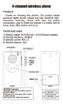
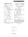

![lincoln log oct 10[2].pub](http://vs1.manualzilla.com/store/data/005855077_1-2c0fc504936f7d4b0b051d0e2d4edff8-150x150.png)