1
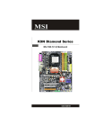
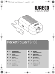
Chapter 1
Product Introduction
Layout
6
5
4
3
2
1
7
8
9
10
26
25
11
24
23
12
13
14 15 16 17 18 19 20
21
22
1. 8-pin ATX_12V Power Connector
14. MCP Fan Connector
2. C51XE
15. Front Panel Connector
3. PCI Express x16 Slots
16. Clear CMOS Jumper
4. PCI Express x1 Slot
17. Serial ATA II Connectors
5. PCI Express x4 Slot
18. USB Connectors
6. PCI Slots
19. MCP55P XE
7. IEEE1394a Connector
20. Serial ATA II Connectors
8. AUX PEX PWR Connector
21. ATA 133/100/66 IDE Connector
9. Speaker Connector
22. 24-pin ATX Power Connector
10. Front Audio Connector
23. DDR2 DIMM Slots
11. FDD Connector
24. Debug LED (optional)
12. COM1 Connector
25. CPU FAN Connector
13. SYS Fan Connector
26. Socket AM2
Note: The above motherboard layout is provided for reference only, please refer to the
physical motherboard.
7
PDF 文件使用 "pdfFactory" 试用版本创建 www.fineprint.com.cn