1
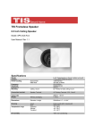
Receiver cuts on and off:
● This could be caused by a short circuit between the positive and negative leads.
Check the connections at the back of the receiver, and then at the speaker; make
sure that no strands of wire from one connector are touching the other connector.
10. Caring For Your Ceiling Speakers
The two most common ways that ceiling speakers are permanently damaged:
1) Not enough power at higher volumes.
2) Too much power at higher volumes.
Contrary to conventional wisdom, far more speakers are damaged as a result of under-powering,
than by overpowering. When a receiver runs out of power, it still tries to reproduce the musical
signal by “clipping” the waveform. At high volume levels this clipping introduces gross amounts of
distortion to the speaker, eventually destroying it. If the sound from your ceiling speakers starts to
sound distorted, turn down the volume.
Having plenty of reserve power will help your speakers reproduce dynamic contrasts and quick
transients of music much more effectively, but you do have to exercise good judgment; too much
power will also permanently damage a speaker. Again, if you hear distortion, turn the volume down.
Specifications
Model number
Description
70V Taps
Woofer
Tweeter
Frequency response (Hz)
Dimensions H x W x D (in)
Cut-out size H x W (in)
Power handling (RMS/Peak)
SPL (1W/1m)
CS420EC
CS420ECT
CS620EC
CS620ECT
8 ohm
NA
4" Poly cone
1" Mylar
60-20,000
8-1/2" dia x 5-7/8" D
6-5/8" dia.
20/40
86 dB
70V / 8 ohm
2, 4, 8, 16 W
4" Poly cone
1" Mylar
60-20,000
8-1/2" dia x 5-7/8" D
6-5/8" dia.
20/40
86 dB
8 ohm
NA
6.5" Poly cone
1" Mylar
50-20,000
11" dia x 7" D
9-9/16" dia.
25/50
88 dB
70V / 8 ohm
2, 4, 8, 16 W
6.5” Poly cone
1” Mylar
50-20,000
11" dia x 7" D
9-9/16” dia.
25/50
88 dB
Warranty Information
Dayton Audio products are constructed by industry experts, and are thoroughly tested before shipment. Dayton Audio products are warranted for the period of one year. This warranty is limited to
manufacturer defects, either in materials or workmanship. Dayton Audio is not responsible for any
consequential on inconsequential damage to any other unit or component or the cost for installation or extraction of any component of the audio system. In the rare case of a product failure,
please contact your place of purchase or call our Customer Support Department at (937) 743-8248.
Warranty Limitations
There are no other warranties, either express or implied, which extend the foregoing, and there are
no warranties of merchantability or fitness for any particular purpose. The warranty will not cover
incidental or consequential damage due to defective or improper use of products. This includes but
is not limited to burnt voice coils, overheating, bent frames, holes in the cone, or broken lead wires.
This warranty gives you specific legal rights and you may also have other rights which vary from
state to state.
Non-Warranty Service: If non-warranty service is required, the product may be sent to the Company
for repair/replacement, transportation prepaid, by calling (937) 743-8248 for details, complete instructions, and service fee charges.
705 Pleasant Valley Dr.
daytonaudio.com
Springboro, OH 45066
tel + 937.743.8248
[email protected] USA
Dayton Audio®
Last Revised: 1/8/2015
CeilingSpeaker
Models: CS420EC/CS420ECT
CS620EC/CS620ECT
User Manual
Congratulations on the purchase of your Dayton Audio® Contractor Series Ceiling Speakers.
These speakers were manufactured with high quality components and engineered to deliver top
quality sound performance.
Long-throw polypropylene cone woofers with rubber surround
Coaxially mounted 1" Mylar tweeter
● Optimized crossover
● Base reflex enclosure
reduce the chance of breaking the plaster. Test fit the speaker
in the hole, the speaker should fit loosely and the speaker
frame should cover the edges of the hole. Repeat these steps
for the other speaker.
●
●
5.
Speaker Cable
Don’t compromise sound quality by using thin, inexpensive
speaker wire, we recommend using a high quality oxygen
free copper speaker cable. For runs less than 50 feet,
we recommend 16 gauge cable, and for longer runs we
recommend 14 gauge or larger cable. For installations with
in-room stereo volume controls we recommend using a four
conductor speaker wire from receiver to volume controls. Most
municipalities require the use of CL2 rated speaker cable for
installation in walls and ceilings. Leave enough speaker cable so
you can stand comfortably on the floor or ladder while connecting
the speaker cable to the speakers.
6.
Speaker Connection
Remove about 8" of the cable jacket to expose the inner
conductors. Strip 1/4" of insulation from each conductor and
connect to the speaker terminals. When connecting the wires
to the speakers, be sure to observe proper polarity. Most CL2
rated speaker cable will have red and black conductors so you will
connect the red wire to the red speaker terminal and the black
wire to the black speaker terminal.
Please read these instructions completely before you begin your installation.
1. Parts Inventory
Your speaker kit should include the following:
● 1 Dayton Audio Contractor Series Enclosed Ceiling Speaker with Grill
● 1 speaker installation / paint masking template
2. Installation Tools
The Dayton Audio speakers can be installed with the following simple tools:
● #2 Phillips screwdriver
●Pencil
● Masking tape
● Wire cutters & wire stripper/crimp tool
● Drill & drill bits
● Stud finder**
● Utility knife or wallboard saw*
* Recommended for use if installing in plaster walls.
** Optional tools to make the installation easier.
3.
Speaker Location
To achieve the best performance from your Dayton Audio speakers, it is important to carefully
select the location for installation. Your ceiling speakers should be installed 5 to 8 feet apart to
ensure proper stereo imaging. Mount each speaker the same distance from the intersecting
walls to maintain a uniform look. Keep the speakers at least 2 feet away from the corners of
the room to avoid overemphasized bass reproduction.
4.
Speaker Installation
Once you have selected the location for your speakers, you are ready to install them.
For high impedance (70 V) applications set the rotary switch to
the wattage to be used. For low impedance (8 ohm) applications
set the rotary switch to the 8 ohm position.
Note: To avoid damage to the speaker, be sure to switch off
the amplifier power when changing the input.
7.
CAUTION: Be certain that there are no electrical wires, water pipes, or heating ducts
in the planned installation area before you start drilling or cutting into the ceiling. If
there is an electrical outlet nearby, turn off the circuit breaker to avoid possible injury.
Ceiling speakers are designed to be mounted in the ceiling between the joists or trusses.
Once you have selected the location, check to be sure you are between the joists or truss.
One method is to tap on the ceiling, you will hear a hollow sound when between two joists or
trusses and a sharper, more solid sound when right on top of, or close to a joist or truss.
An easier, more accurate method for finding the location of joists or trusses is to use a
stud finder.
The Contractor Series Ceiling speakers include a two-part template. Remove the center circle
from the template, this is a paint masking template to use if you choose to paint the speaker
frames and grill. The outer ring is used to mark the cut-out for the speakers.
Once you have established that your chosen location is between two joists or trusses, and
that there are no obstructions in the ceiling, tape your speaker template to the ceiling and
lightly trace around the inside edge with a pencil and drill a 1" hole in the center of the
template outline. Next, use a piece of stiff wire (a coat hanger works well), bend it 8" from the
end at a 90 degree angle. Insert the bent part of the coat hanger into the 1" hole and rotate
the wire in a complete circle to check for obstructions. If the wire hits a stud on either side,
reposition your template to the left or right and mark the outline again. Keep the pilot hole
within the template outline.
If the ceiling is made of drywall, simply cut the marked area with your utility knife or drywall
saw. If the ceiling is made of plaster, you should use a saw with a higher tooth count to
Final Installation
To install the speakers into the ceiling, remove the grills,
this will give you access to the mounting screws. Turn
the mounting clamps so they are positioned as in the
illustration, this will allow the speakers to clear the hole for
installation. Insert the speaker into the hole, and tighten the
mounting screws. As you turn each screw, the mounting
clamps will rotate outward to engage ceiling material.
CAUTION: Do Not Over-Tighten the Clamps. Too much torque may snap off the lug and the
speaker will not seat securely. A snug fit is all that is necessary to assure proper performance.
8.
Painting Speakers
If you choose to paint the speaker grill and/or frame we have provided a “Paint Masking Template” to cover the woofer/tweeter assembly and help prevent possible damage. Do not try to
paint the frame and grill assembly together. The grill should always be painted separately.
Do not apply heavy coats of paint that might block the perforations in the grill.
9.Troubleshooting
Should your speakers not work properly, check the following:
No sound from speakers:
● Most stereo receivers have an A/B speaker selector switch. Make certain that
this switch is in the proper position.
● Mute feature is activated.
One speaker is playing while the other is not:
● Check the balance control on the receiver. Make sure it is centered.
● Loose connection at either the receiver or the speaker. Double check connections.
● Bad speaker cable. Replace suspect speaker cable.