1
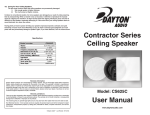
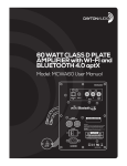
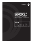
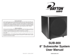
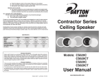
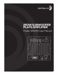
70V COMMERCIAL
SPEAKER PAIR
Model: QS204-4/ QS204W-4
User Manual
Congratulations on the purchase of your Dayton Audio® QS204-4 Commercial Speakers. These rugged, all-purpose speakers are designed to deliver reliable, highquality audio in commercial environments and professional installations while withstanding outdoor environments. They feature a modular “Quadrant-style” design,
weather-resistant ABS construction, high-quality components, and exclusive acoustic design and tuning by Dayton Audio for outstanding performance and value.
l
Dual 4" polypropylene cone woofers with rubber surround
1" Treated silk dome tweeter
l Versatile multi-angle mounting bracket
l Integral 70V transformer with selectable taps
l Suitable for indoor or outdoor installation
l
Please read these instructions completely before you begin your installation.
1)
Speaker Connection
NOTE: Make sure to use the appropriate type of two-conductor speaker cable for your application. Note that most municipalities require the use of
CL2-rated speaker cable for cable runs through walls and ceilings.
Speaker Wiring: Remove about 8" of the cable jacket to expose the inner conductors. Strip 1/4" of insulation from each conductor and connect to
the speaker terminals. When connecting the wires to the speakers, be sure to observe proper polarity for the best sound. Most CL2 rated speaker
cable has red and black conductors within the jacket, so connect the red wire to the red speaker terminal and the black wire to the black speaker
terminal. The red (+) terminal on the back of the speaker should correspond to the red (+) terminal on the amplifier, and same for the black terminal.
The speaker terminals are of the push-type, so push in on each terminal to allow the wire to be inserted. Torquing the terminal in any way is not
necessary and may cause damage.
NOTE: This speaker is pre-configured from the factory for 70V/100V operation. This may cause low output when connected directly to an amplifier.
To use this speaker with a conventional (non-70V/100V) audio system, follow the below process to change the 70V/100V tap setting.
Step 1: Remove the grill
The entire grill frame should be
removed by hand; tools are not
necessary, though some force may be
required to dislodge the grill fasteners.
Grasp the frame at a corner, and pull
directly away from the speaker housing.
Step 2: Set 70V/100V Tap to 4 OHMS.
Using a screwdriver or other flatblade tool, turn the tap selector knob
until the 4 OHMS setting is selected.
This will remove the transformer from
the signal path and allow a conventional amplifier to drive the speaker to
full output.
Step 3: Replace Grill Frame
To reinstall the grill frame, align the
pegs on the frame with the openings
on the speaker enclosure, then press
in firmly. Rotate the logo as required
for proper orientation when installed.
NOTE: If this speaker will be used
with a 70V/100V distributed audio
system, do not set the 70V/100V tap to
the 4 OHMS setting. Doing so may damage your speaker when playing. Instead,
choose the desired 70/100V tap (the one that
provides the desired amount of output) using
the selector switch and the adjustment process described above. The speaker is already pre-configured
for use with a 70V/100V system. If you are unsure what type of audio system you have, consult a professional installer before continuing.
2)
Choose Speaker Location
Because of their well-behaved off-axis response and excellent dispersion, your new Dayton Audio speakers are less critical to position than most
commercial loudspeakers. Simply place them 5-8 feet apart wherever you desire music for the best possible performance. If you will be installing
your speakers outdoors, select locations facing your listening area that are protected from rain, snow, and out of direct sunlight for extended product
life. Because these speakers feature an open bass-reflex port, avoid mounting them facing upward in an area exposed to weather to prevent collecting standing water.
3)
Choose Speaker Installation
Once you have selected the location for your speakers, you are ready to install them.
CAUTION: Be certain that there are no electrical wires, water pipes, or heating ducts in the planned installation area before you begin drilling. If
there is an electrical outlet nearby, turn off the circuit breaker to avoid possible injury.
NOTE: Your Dayton Audio QS204-4 speakers are compact, but substantial in weight. They should be mounted into solid structure, not drywall. If
drywall mounting is required, use high-strength anchors designed for heavy loads such as light fixtures. To avoid personal injury, please make sure
the location you choose for mounting your speakers can safely support their weight.
(2)
Installation Options: Please see the below images for installation examples.
(A) Horizontal Wall Mount (B) Vertical Wall Mount (C) Horizontal Wall Mount – Two Speakers Array (D) Corner Wall Mount – Three Speakers Array
(E) Pendant Mount – Four Speakers Array (Requires Array Bracket Sold Separately)
To mark the proper locations for drilling, place the multi-angle bracket against the mounting surface and choose the holes you want to use for mounting. Then use a pencil to mark the hole locations on the mounting surface prior to drilling. Remove the bracket before drilling the holes, in order to avoid
damage to the bracket. After drilling the mounting holes, install the large half of the bracket firmly to the mounting surface in the desired orientation using
appropriate mounting hardware.
4)
Final Installation
To complete mounting the speaker, choose the desired orientation (vertical or horizontal) and then slide the speaker into the large half of the bracket, then
install the small half of the bracket (the endcap) using the long screws provided. Note: If the speaker does not slide easily into the bracket in the desired
orientation, rotate it 180 degrees and try again. The speaker is intended to slide into the bracket in only one direction.
CAUTION: Do not over-tighten the endcap screws. Too much torque may crack the plastic bracket. A snug fit is all that is necessary to assure proper performance.
Step 1: Install the multi-angle bracket
Horizontal Wall Mount
Vertical Wall Mount
Option 1
Two Speakers Array
Three Speakers Array
Option 2
Step 2: Install the speaker
Horizontal Wall Mount
Vertical Wall Mount
Option 1
Step 2a: Install speaker
Two Speakers Array
Step 2b: Install endcap
Three Speakers Array
(3)
Option 2
Option 3
5)
Troubleshooting
Should your speakers not work properly, check the following:
No sound from speakers or quiet/strange sound:
l Make certain you observed proper polarity for both speaker inputs. Check the connections at the back of the receiver, and then at the speaker.
l Verify that the amplifier is powered on and the volume is turned up.
l Check that the correct transformer tap is selected for your application. If you are using a stereo amplifier or a receiver, use the 4-ohm tap.
l Mute feature or protection mode is activated. Check for short circuits in speaker wiring.
One speaker is playing while the other is not playing or plays quietly:
l Check the balance control on the receiver. Make sure it is centered.
l Loose connection at either the receiver or the speaker. Double check connections.
l Bad speaker cable. Replace the suspect speaker cable.
Amplifier/Receiver cuts on and off:
l This could be caused by a short circuit between the positive and negative leads. Check the connections at the back of the receiver,
and then at the speaker; make sure that no strands of wire from one connector are touching the other connector.
6)
Caring For Your Speakers
The two most common ways that loudspeakers are permanently damaged:
1) Not enough power at higher volumes.
2) Too much power at higher volumes.
Contrary to conventional wisdom, far more speakers are damaged as a result of under-powering, than by overpowering. When an amplifier runs out of
power, it still tries to reproduce the musical signal by “clipping” the waveform. At high volume levels this clipping sends extreme amounts of distortion
energy to the speaker, eventually destroying it. If the sound from your speakers starts to sound distorted, turn down the volume.
Having plenty of reserve power will help your speakers reproduce dynamic contrasts and quick transients of music much more effectively, but use good
judgment; too much power will also permanently damage a speaker. Again, if you hear distortion or audible distress, turn the volume down.
The QS204-4 speakers are designed to withstand outdoor environments, including incidental exposure to water. They are not designed to be washed using a pressure washer or hose nozzle. If debris accumulates on the housing of the speaker, use a damp sponge or cloth to remove it. This product is not
suitable for washdown duty or locations requiring explosion-proof electrical hardware.
Specifications
Model Number:
Description:
Woofer:
Tweeter:
Frequency Response:
Impedance:
70V/100V Taps:
Power Handling (RMS/Peak):
SPL 1W/1m:
Dimensions HxWxD:
Color:
Weight:
Ingress Protection (IP) Rating:
QS204-4, QS204W-4
Commercial Indoor/Outdoor Speaker Pair
(2) 4" Mineral-Filled Polypropylene
1" Treated Silk Dome
70-20,000 Hz
4 Ohms/70V
40W/20W/10W/5W/2.5W/4 Ohms
40W / 75W
87 dB
5.4" x 15.2" x 10.3"
Black, White
7.5 lb
IP 51
Warranty Information
Dayton Audio® products are constructed by industry experts, and are thoroughly tested before shipment. Dayton Audio®
products are warranted for the period of one year. This warranty is limited to manufacturer defects, either in materials or
workmanship. Dayton Audio® is not responsible for any consequential on inconsequential damage to any other unit or component or the cost for installation or extraction of any component of the audio system. In the rare case of a product failure,
please contact your place of purchase or call our Customer Support Department at (937) 743-8248.
Warranty Limitations
There are no other warranties, either express or implied, which extend the foregoing, and there are no warranties of merchantability or fitness for any particular purpose. The warranty will not cover incidental or consequential damage due to
defective or improper use of products. This includes but is not limited to burnt voice coils, overheating, bent frames, holes in
the cone, or broken lead wires.
This warranty gives you specific legal rights and you may also have other rights which vary from state to state.
Non-Warranty Service: If non-warranty service is required, the product may be sent to the Company for repair/replacement,
transportation prepaid, by calling (937) 743-8248 for details, complete instructions, and service fee charges.
daytonaudio.com
tel + 937.743.8248
[email protected]
Dayton Audio®
(4)
705 Pleasant Valley Dr.
Springboro, OH 45066
USA
Last Revised: 1/16/2015