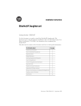
1
Installation Instructions
Stratix 6000 Ethernet Managed Switches
Catalog Numbers 1783-EMS08T, 1783-EMS04T
Topic
Page
Important User Information
2
North American Hazardous Location Approval
3
European Hazardous Location Approval
4
Preventing Electrostatic Discharge
6
About the Switches
7
Install the Switches
7
DIN Rail Mounting
8
Panel Mounting
10
Wire the Switch
11
Connect the Copper Ethernet Ports
12
Install an Optional SFP Module
13
Connect the Fiber Optic Ethernet Port
14
Grounding Considerations
15
Use the Switch
16
Specifications
18
Additional Resources
22
2 Stratix 6000 Ethernet Managed Switches
Important User Information
Read this document and the documents listed in the additional resources section about installation, configuration, and
operation of this equipment before you install, configure, operate, or maintain this product. Users are required to familiarize
themselves with installation and wiring instructions in addition to requirements of all applicable codes, laws, and standards.
Activities including installation, adjustments, putting into service, use, assembly, disassembly, and maintenance are required to
be carried out by suitably trained personnel in accordance with applicable code of practice.
If this equipment is used in a manner not specified by the manufacturer, the protection provided by the equipment may be
impaired.
In no event will Rockwell Automation, Inc. be responsible or liable for indirect or consequential damages resulting from the use
or application of this equipment.
The examples and diagrams in this manual are included solely for illustrative purposes. Because of the many variables and
requirements associated with any particular installation, Rockwell Automation, Inc. cannot assume responsibility or liability for
actual use based on the examples and diagrams.
No patent liability is assumed by Rockwell Automation, Inc. with respect to use of information, circuits, equipment, or software
described in this manual.
Reproduction of the contents of this manual, in whole or in part, without written permission of Rockwell Automation, Inc., is
prohibited.
Throughout this manual, when necessary, we use notes to make you aware of safety considerations.
WARNING: Identifies information about practices or circumstances that can cause an explosion in a hazardous
environment, which may lead to personal injury or death, property damage, or economic loss.
ATTENTION: Identifies information about practices or circumstances that can lead to personal injury or death,
property damage, or economic loss. Attentions help you identify a hazard, avoid a hazard, and recognize the
consequence.
IMPORTANT Identifies information that is critical for successful application and understanding of the product.
Labels may also be on or inside the equipment to provide specific precautions.
SHOCK HAZARD: Labels may be on or inside the equipment, for example, a drive or motor, to alert people that
dangerous voltage may be present.
BURN HAZARD: Labels may be on or inside the equipment, for example, a drive or motor, to alert people that
surfaces may reach dangerous temperatures.
ARC FLASH HAZARD: Labels may be on or inside the equipment, for example, a motor control center, to alert
people to potential Arc Flash. Arc Flash will cause severe injury or death. Wear proper Personal Protective
Equipment (PPE). Follow ALL Regulatory requirements for safe work practices and for Personal Protective
Equipment (PPE).
Rockwell Automation Publication 1783-IN004B-EN-P - June 2014
Stratix 6000 Ethernet Managed Switches 3
North American Hazardous Location Approval
The following information applies when
operating this equipment in hazardous
locations.
Informations sur l’utilisation de cet
équipement en environnements dangereux.
Products marked "CL I, DIV 2, GP A, B, C, D" are
suitable for use in Class I Division 2 Groups A, B, C, D,
Hazardous Locations and nonhazardous locations
only. Each product is supplied with markings on the
rating nameplate indicating the hazardous location
temperature code. When combining products
within a system, the most adverse temperature
code (lowest "T" number) may be used to help
determine the overall temperature code of the
system. Combinations of equipment in your system
are subject to investigation by the local Authority
Having Jurisdiction at the time of installation.
Les produits marqués "CL I, DIV 2, GP A, B, C, D" ne
conviennent qu'à une utilisation en environnements
de Classe I Division 2 Groupes A, B, C, D dangereux et
non dangereux. Chaque produit est livré avec des
marquages sur sa plaque d'identification qui
indiquent le code de température pour les
environnements dangereux. Lorsque plusieurs
produits sont combinés dans un système, le code de
température le plus défavorable (code de température
le plus faible) peut être utilisé pour déterminer le code
de température global du système. Les combinaisons
d'équipements dans le système sont sujettes à
inspection par les autorités locales qualifiées au
moment de l'installation.
EXPLOSION HAZARD • Do not disconnect equipment
unless power has been removed
or the area is known to be
nonhazardous.
• Do not disconnect connections
to this equipment unless power
has been removed or the area is
known to be nonhazardous.
Secure any external
connections that mate to this
equipment by using screws,
sliding latches, threaded
connectors, or other means
provided with this product.
• Substitution of components
may impair suitability for Class
I, Division 2.
• If this product contains
batteries, they must only be
changed in an area known to be
nonhazardous.
RISQUE D’EXPLOSION –
• Couper le courant ou s'assurer
que l'environnement est
classé non dangereux avant
de débrancher l'équipement.
• Couper le courant ou s'assurer
que l'environnement est
classé non dangereux avant
de débrancher les
connecteurs. Fixer tous les
connecteurs externes reliés à
cet équipement à l'aide de vis,
loquets coulissants,
connecteurs filetés ou autres
moyens fournis avec ce
produit.
• La substitution de
composants peut rendre cet
équipement inadapté à une
utilisation en environnement
de Classe I, Division 2.
• S'assurer que
l'environnement est classé
non dangereux avant de
changer les piles.
Rockwell Automation Publication 1783-IN004B-EN-P - June 2014
4 Stratix 6000 Ethernet Managed Switches
WARNING: For 1783-EMS08T switches only, when you insert or remove the small
form-factor pluggable (SFP) optical transceiver while power is on, an electrical arc
can occur. This could cause an explosion in hazardous location installations.
Be sure that power is removed or the area is nonhazardous before proceeding.
European Hazardous Location Approval
ATTENTION: This equipment is intended for use in potentially explosive
atmospheres as defined by European Union Directive 94/9/EC and has been found
to comply with the Essential Health and Safety Requirements relating to the design
and construction of Category 3 equipment intended for use in potentially explosive
atmospheres, given in Annex II to this Directive.
Compliance with the Essential Health and Safety Requirements has been assured
by compliance with EN 60079-15 and EN 60079-0.
WARNING:
• This equipment is not resistant to sunlight or other sources of UV radiation.
• This equipment must be installed in an enclosure providing at least IP54
protection when applied in Zone 2 environments.
• This equipment shall be used within its specified ratings defined by Rockwell
Automation.
• Provision shall be made to prevent the rated voltage from being exceeded by
transient disturbances of more than 40% when applied in Zone 2
environments.
• Secure any external connections that mate to this equipment by using screws,
sliding latches, threaded connectors, or other means provided with this
product.
• Do not disconnect equipment unless power has been removed or the area is
known to be nonhazardous.
Rockwell Automation Publication 1783-IN004B-EN-P - June 2014
Stratix 6000 Ethernet Managed Switches 5
Environment and Enclosure
ATTENTION: This equipment is intended for use in a Pollution Degree 2 industrial
environment, in overvoltage Category II applications (as defined in IEC publication
60664-1), at altitudes up to 2000 m (6562 ft) without derating.
This equipment is considered Group 1, Class A industrial equipment according to
IEC/CISPR Publication 11. Without appropriate precautions, there may be potential
difficulties ensuring electromagnetic compatibility in other environments due to
conducted as well as radiated disturbance.
This equipment is supplied as open-type equipment. It must be mounted within an
enclosure that is suitably designed for those specific environmental conditions that
will be present and appropriately designed to prevent personal injury resulting
from accessibility to live parts. The enclosure must have suitable flame-retardant
properties to prevent or minimize the spread of flame, complying with a flame
spread rating of 5VA, V2, V1, V0 (or equivalent) if non-metallic. The interior of the
enclosure must be accessible only by the use of a tool. Subsequent sections of this
publication may contain additional information regarding specific enclosure type
ratings that are required to comply with certain product safety certifications.
In addition to this publication, see the following publications:
• Publication 1770-4.1, Industrial Automation Wiring and Grounding
Guidelines, for additional installation requirements
• NEMA 250 and IEC 60529, as applicable, for explanations of the degrees of
protection provided by different types of enclosures
Rockwell Automation Publication 1783-IN004B-EN-P - June 2014
6 Stratix 6000 Ethernet Managed Switches
Preventing Electrostatic Discharge
ATTENTION: This equipment is sensitive to electrostatic discharge, which can
cause internal damage and affect normal operation. Follow these guidelines when
you handle this equipment:
•
•
•
•
•
•
Touch a grounded object to discharge potential static.
Wear an approved grounding wriststrap.
Do not touch connectors or pins on component boards.
Do not touch circuit components inside the equipment.
Use a static-safe workstation, if available.
Store the equipment in appropriate static-safe packaging when not in use.
ATTENTION: To comply with the CE Low Voltage Directive (LVD), all connections ot
this equipment must be powered from a source compliant with the following:
Safety Extra Low Voltage (SELV) or Protected Extra Low Voltage (PELV).
ATTENTION: To comply with ETL restrictions, all connections to this equipment
must be powered from a source compliant with the following: Class 2.
Rockwell Automation Publication 1783-IN004B-EN-P - June 2014
Stratix 6000 Ethernet Managed Switches 7
About the Switches
These switches provide real-time access to network data through the
Logix-based control system. The switches integrate into Logix programs and
update tags automatically.
Use the switches to assist in continuously monitoring your network and
implementing changes.
The figure shows Ethernet port identification for the 1783-EMS08T 8-port and
the 1783-EMS04T 4-port switches.
Ethernet Port Identification
1783-EMS04T
1
2
1
2
3
4
3
4
1783-EMS08T
8
6
4
2
8 7
6 5
4 3
2 1
7
5
3
1
31871-M
Install the Switches
Mount the switches, as shown, in the vertical position only. We do not
recommend horizontal mounting due to thermal considerations. When
mounting:
• Provide 50 mm (2 in.) of space on all sides for adequate heat dissipation.
• Leave 100 mm (4 in.) for installation and removal if using the fiber-optic
port on the bottom of the 1783-EMS08T switch.
IMPORTANT
Use care with the plastic DIN rail clip.
Rockwell Automation Publication 1783-IN004B-EN-P - June 2014
8 Stratix 6000 Ethernet Managed Switches
WARNING: If you connect or disconnect the communication cable with power
applied to this module or any device on the network, an electrical arc can occur. This
could cause an explosion in hazardous location installations.
Be sure that power is removed or the area is nonhazardous before proceeding.
WARNING: If you connect or disconnect wiring while the field-side power is on, an
electrical arc can occur. This could cause an explosion in hazardous location
installations. Be sure that power is removed or the area is nonhazardous before
proceeding.
DIN Rail Mounting
Read this section for information on how to install and remove a switch using
DIN rail mounting.
Install the Switch
To install the switch on DIN rail, proceed as follows.
1. Mount your DIN rail.
2. Snap the DIN-rail latch into the closed position.
3. Hook the top slot over the DIN rail and push the switch into position
on the DIN rail.
Rockwell Automation Publication 1783-IN004B-EN-P - June 2014
Stratix 6000 Ethernet Managed Switches 9
Remove the Switch
To remove the switch from DIN rail, proceed as follows.
1. Place a screwdriver in the DIN-rail latch at the bottom of the switch.
2. Hold the switch and pry downward on the latch until the switch is
released from the DIN rail.
Rockwell Automation Publication 1783-IN004B-EN-P - June 2014
10 Stratix 6000 Ethernet Managed Switches
Panel Mounting
To panel mount a switch, create a mounting template, referring to the figure,
which shows a 1783-EMS08T switch with an SFP module installed.
Provide 15 mm (0.6 in.) clearance for DIN-rail latch movement during
installation and removal. Dimensions in the figure are in mm (in.). These views
are not actual size.
52.07 (2.05)
118 (4.64)
107 (4.21)
12 (0.47)
12 (0.47)
27.7 (1.09)
SFP Module Installed
Rockwell Automation Publication 1783-IN004B-EN-P - June 2014
88.9 (3.50)
Stratix 6000 Ethernet Managed Switches 11
Wire the Switch
Read this section for information about external power supply wiring.
Provide low voltage DC power to the switch by using the screw terminals at the
bottom of the switch.
1
2
3
4 5 6
Item
Description
Item
Description
1
Side view
4
Ground
2
Bottom view
5
DC-
3
Fiber optic SFP slot (1783-EMS08T switch only)
6
DC +
Rockwell Automation Publication 1783-IN004B-EN-P - June 2014
12 Stratix 6000 Ethernet Managed Switches
Follow these steps to wire the switch.
1. Be sure power to the power supply is turned off.
2. Be sure you have the proper gauge of wire for your power supply.
3. Strip approximately 0.9 mm (0.35 in.) from each end of the wire.
4. Using a Phillips screwdriver, loosen the screw terminals on the terminal
strip at the bottom of the switch.
5. Connect DC+ (24V DC nominal) from the power supply to the DC+
terminal and tighten the screw.
6. Connect DC- (0V DC) from the power supply to the DC- terminal and
tighten the screw.
7. Connect functional earth ground to the ground terminal and tighten
the screw.
8. Refer to the grounding considerations on page 15.
9. Tug gently on the wires to ensure the connections are secure.
Connect the Copper Ethernet Ports
Follow these steps to connect the copper Ethernet ports on the switch.
1. Locate the copper Ethernet RJ-45 ports on the switch.
2. Connect one end of an Ethernet cable to one of the copper ports on the
switch.
3. Connect the other end of the Ethernet cable to a device in your Ethernet
network.
Rockwell Automation Publication 1783-IN004B-EN-P - June 2014
Stratix 6000 Ethernet Managed Switches 13
Install an Optional SFP Module
To install a 1G fiber small form-factor pluggable (SFP) module into the fiber
optic Ethernet slot on the bottom to the 1783-EMS08T switch, grasp the SFP
module on the sides and insert it into the slot until you feel the connector snap
into place.
TIP
For detailed instructions on installing, removing, and connecting to SFP
modules, see the documentation that shipped with the SFP module.
Available SFP modules include the following:
• 1783-SFP1GSX - 1000BASE-SX multi-mode fiber transceiver
• 1783-SFP1GLX - 1000BASE-LX single-mode fiber transceiver
8 7
6 5
4 3
2 1
31877-M
ATTENTION: SFP modules are static sensitive devices. Always use an ESD wrist
strap or similar individual grounding device when handling SFP modules.
IMPORTANT
Installing and removing an SFP module can shorten its useful life. Do not
remove and insert SFP modules more often than is absolutely necessary.
Rockwell Automation Publication 1783-IN004B-EN-P - June 2014
14 Stratix 6000 Ethernet Managed Switches
ATTENTION:
If the SFP module cannot be fully inserted, stop!
Do not force the module into the slot.
Rotate the SFP module 180 degrees and try again.
ATTENTION: Under certain conditions, viewing the optical port may expose the
eye to hazard. When viewed under some conditions, the optical port may expose
the eye beyond the maximum permissible exposure recommendations.
IMPORTANT
The 1783-EMS08T switch supports 1G fiber SFP modules only.
WARNING: For 1783-EMS08T switches only, when you insert or remove the small
form-factor pluggable (SFP) optical transceiver while power is on, an electrical arc
can occur.
This could cause an explosion in hazardous location installations.
Be sure that power is removed or the area is nonhazardous before proceeding.
Connect the Fiber Optic Ethernet Port
Follow these steps to connect the fiber optic Ethernet port (on the SFP) in the
1783-EMS08T switch after inserting the SFP module.
1. Connect the duplex LC connector end of the fiber optic cable, in the
proper orientation, to the fiber optic Ethernet port on the SFP module
installed at the bottom of the switch, as described in Install an Optional
SFP Module.
2. Connect the other end of the cable to a device in your network or to
another switch if connecting switches together.
Rockwell Automation Publication 1783-IN004B-EN-P - June 2014
Stratix 6000 Ethernet Managed Switches 15
Grounding Considerations
ATTENTION: You must provide an acceptable grounding path for each device in
your application. For more information on proper grounding guidelines, refer to
publication 1770-4.1, Industrial Automation Wiring and Grounding Guidelines.
This product is intended to be mounted to a well-grounded mounting surface
such as a metal panel. The functional earth ground connection to the product is
through the specified pin on the DC connection terminals.
IMPORTANT
The ground connection is required at the grounding pin on the DC connection
terminals.
Refer to publication 1770-4.1, Industrial Automation Wiring and Grounding
Guidelines, for additional information.
Rockwell Automation Publication 1783-IN004B-EN-P - June 2014
16 Stratix 6000 Ethernet Managed Switches
Use the Switch
To start using your switch, follow this procedure. For information about the
status indicators on the switch, refer to the Stratix 6000™ Ethernet Managed
Switch User Manual, publication 1783-UM001.
1. Connect to your computer’s LAN card by using patch cable or
cross-over cable and following these steps.
a. Choose Start > Settings > Network Connections and right-click
Local Area Connection and Properties.
b. From the Local Area Connection Properties menu, check Ethernet
Protocol (TCP/IP), and click Properties.
Rockwell Automation Publication 1783-IN004B-EN-P - June 2014
Stratix 6000 Ethernet Managed Switches 17
c. From the Ethernet Protocol (TCP/IP) Properties menu, change the
IP address to 192.168.1.3 and Subnet mask to 255.255.255.0.
2. Connect to the switch via a Web browser by using these steps.
a. Open a browser window.
b. Enter the default IP address of 192.168.1.1 in the address bar, press
Enter, and note the following defaults:
• User name should be left blank.
• Password is PASSWORD.
3. Configure the switch.
You can get complete configuration instructions by clicking the link to
view the embedded manual.
4. If the switch is to scan in a Logix 5000™ program, refer to the appropriate
section of your embedded manual.
Rockwell Automation Publication 1783-IN004B-EN-P - June 2014
18 Stratix 6000 Ethernet Managed Switches
Specifications
Stratix 6000 Ethernet Managed Switches
Attribute
1783-EMS08T
1783-EMS04T
Power requirements
12…48V DC
Class 2/SELV
250 mA @ 24V DC
12…48 V DC
Class 2/SELV
100 mA @ 24V DC
Power dissipation
5.8 W @ 60 °C (140 °F) max
2.6 W @ 60 °C (140 °F) max
Thermal dissipation
24.6 BTU/hr @ 60 °C (140 °F) max
Network ports
8 RJ-45 10/100 full/half duplex ports,
optional SFP transceiver port
Protocols
TCP/IP, EtherNet/IP, Telnet, Http, DHCP, BOOTP, FTP, IGMP, SMTP
Indicators
16 port indicators,
3 status indicators
EtherNet/IP features
MAC ID management, bandwidth alarming, port control, link status, scaled
bandwidth information,
connections active
Switch features
VLAN, IGMP snooping, IGMP query V1
and V2, DHCP server, BOOTP server,
QoS, port mirroring
IGMP snooping, IGMP query V1 and V2,
DHCP server, BOOTP server, QoS, port
mirroring
Options
1 gigabyte fiber optic transceiver
—
Voltage variation
IEC 61000-4-29:
10 ms interruption on DC supply ports
Enclosure type rating
Meets IP20
Inrush current, max
2.2 A
Isolation voltage
50 V (continuous), Basic Insulation Type
No isolation between individual Ethernet ports
Routine tested at 707V AC for 1 s, DC power ports to ground and DC power ports to
Ethernet ports
Rockwell Automation Publication 1783-IN004B-EN-P - June 2014
4 RJ-45 10/100 full/half duplex ports
8 port indicators,
2 status indicators
Stratix 6000 Ethernet Managed Switches 19
Stratix 6000 Ethernet Managed Switches (continued)
Attribute
1783-EMS08T
Wire size
Ethernet connections:
RJ45 connector according to IEC 60603-7, 2 or 4 pair Category 5e min cable
according to TIA 568-B.1 or Category 5 cable according to ISO/IEC 24702
DC Power connections:
0.33... 3.3 mm2 (22...12 AWG) solid or stranded copper wire rated at 75 °C
(167 °F) or greater, 1.2 mm (3/64 in.) insulation max
Functional ground connection:
3.3 mm2 (12 AWG) solid or stranded copper wire rated at 75 °C (167 °F) or greater
Torque
DC power and functional ground: 1.36 Nm (12 pound-inches)
Fiber optic Ethernet
data rate(1)
1000 Mbps(1)
—
Fiber optic connecting
mode(1)
Full duplex(1)
—
Fiber optic connector
type(1)
LC(1)
—
Wiring category(2) (3)
2 - on DC power ports
2 - on Ethernet ports
North American temp
code
T4
IEC temp code
T4
(1)
(2)
(3)
1783-EMS04T
Available when you purchase an optional SFP module.
Use this Conductor Category information for planning conductor routing. Refer to Industrial Automation Wiring and
Grounding Guidelines, publication 1770-4.1.
Use this Conductor Category information for planning conductor routing as described in the appropriate system-level
installation manual.
Rockwell Automation Publication 1783-IN004B-EN-P - June 2014
20 Stratix 6000 Ethernet Managed Switches
Environmental Specifications
Attribute
1783-EMS08T, 1783-EMS04T
Emissions
CISPR 11: Group 1, Class A
Temperature, operating
IEC 60068-2-1 (Test Ad, Operating Cold),
IEC 60068-2-2 (Test Bd, Operating Dry Heat),
IEC 60068-2-14 (Test Nb, Operating Thermal Shock):
0…60 °C (32…140 °F)
Temperature, nonoperating
IEC 60068-2-1 (Test Ab, Unpackaged Non-operating Cold),
IEC 60068-2-2 (Test Bb, Unpackaged Non-operating Dry Heat),
IEC 60068-2-14 (Test Na, Unpackaged Non-operating Thermal Shock):
-40…85 °C (-40…185 °F)
Relative humidity
IEC 60068-2-30 (Test Db, Unpackaged Damp Heat):
5…95% non-condensing
Vibration
IEC 60068-2-6 (Test Fc, Operating):
2 g @ 10…500 Hz
Operating shock
IEC 60068-2-27 (Test Ea, Unpackaged Shock): 15 g
Nonoperating shock
IEC 60068-2-27 (Test Ea, Unpackaged Shock): 30 g
ESD immunity
IEC 61000-4-2:
6 kV contact discharges
8 kV air discharges
Radiated RF immunity
IEC 61000-4-3:
10V/m with 1 kHz sine-wave 80% AM from 80…2000 MHz
10V/m with 200 Hz 50% Pulse 100% AM at 900 MHz
10V/m with 200 Hz 50% Pulse 100% AM at 1890 MHz
1V/m with 1 kHz sine-wave 80% AM from 2000…2700 MHz
EFT/B immunity
IEC 61000-4-4:
±2 kV at 5 kHz on power ports
±1 kV at 5 kHz on Ethernet ports
Surge transient immunity
IEC 61000-4-5:
±1kV line-line (DM) and ±2 kV line-earth (CM) on DC power ports
±2 kV line-earth (CM) on shielded Ethernet port
Conducted RF immunity
IEC 61000-4-6:
10V rms with 1 kHz sine-wave 80% AM
from 150 kHz…80 MHz
Magnetic field immunity
IEC 61000-4-8:
30A/m long duration and 300A/m short duration
at 50 and 60 Hz
Rockwell Automation Publication 1783-IN004B-EN-P - June 2014
Stratix 6000 Ethernet Managed Switches 21
Certifications
Certifications
(when product is marked)(1)
1783-EMS08T, 1783-EMS04T
CE
European Union 2004/108/EC EMC Directive, compliant with:
EN 61326-1; Meas./Control/Lab., Industrial Requirements
EN 61000-6-2; Industrial Immunity
EN 61000-6-4; Industrial Emissions
EN 61131-2; Programmable Controllers
(Clause 8, Zone A & B)
C-Tick
AS/NZS CISPR 11; Industrial Emissions
Ex
EN 60079-15; Potentially Explosive Atmospheres, Protection "n"
(II 3 G Ex nA IIC T4)
EN 60079-0; General Requirements (Zone 2)
EtherNet/IP
ODVA conformance tested to EtherNet/IP specifications
c-UL-us
UL Listed Information Technology Equipment, certified for US and
Canada. See UL File E151729.
c-ETL-us
ETL Listed Industrial Control Equipment, certified for US and Canada.
c-ETL-us
ETL Listed for Class I, Division 2 Group A,B,C,D Hazardous Locations,
certified for U.S. and Canada
(1)
See the Product Certification link at www.ab.com for Declarations of Conformity, Certificates, and other certification
details.
Rockwell Automation Publication 1783-IN004B-EN-P - June 2014
22 Stratix 6000 Ethernet Managed Switches
Additional Resources
These documents contain additional information concerning related products
from Rockwell Automation.
Resource
Description
EtherNet/IP Industrial Protocol White Paper,
publication ENET-WP001
Describes how to implement services and data
objects on a TCP/UDP/IP based Ethernet network.
Stratix 6000 Ethernet Managed Switch User Manual,
publication 1783-UM001
Provides details about how to configure and use the
switch.
Stratix 6000 Ethernet Managed Switch Release
Notes, publication 1783-RN003
Provides updates on switch operation.
Industrial Automation Wiring and Grounding
Guidelines, publication 1770-4.1
Provides general guidelines for installing a Rockwell
Automation industrial system.
Product Certifications website, http://www.ab.com
Provides declarations of conformity, certificates, and
other certification details.
You can view or download publications at
http://literature.rockwellautomation.com. To order paper copies of technical
documentation, contact your local Allen-Bradley distributor or Rockwell
Automation sales representative.
Rockwell Automation Publication 1783-IN004B-EN-P - June 2014
Stratix 6000 Ethernet Managed Switches 23
Notes:
Rockwell Automation Publication 1783-IN004B-EN-P - June 2014
Rockwell Automation Support
Rockwell Automation provides technical information on the Web to assist you in using its products.
At http://www.rockwellautomation.com/support you can find technical and application notes, sample code, and links to
software service packs. You can also visit our Support Center at https://rockwellautomation.custhelp.com/ for software
updates, support chats and forums, technical information, FAQs, and to sign up for product notification updates.
In addition, we offer multiple support programs for installation, configuration, and troubleshooting. For more information,
contact your local distributor or Rockwell Automation representative, or visit
http://www.rockwellautomation.com/services/online-phone.
Installation Assistance
If you experience a problem within the first 24 hours of installation, please review the information that's contained in this
manual. You can also contact a special Customer Support number for initial help in getting your product up and running.
United States or Canada
1.440.646.3434
Use the Worldwide Locator at
Outside United States or Canada http://www.rockwellautomation.com/rockwellautomation/support/overview.page, or
contact your local Rockwell Automation representative.
New Product Satisfaction Return
Rockwell Automation tests all of its products to help ensure that they are fully operational when shipped from the
manufacturing facility. However, if your product is not functioning and needs to be returned, follow these procedures.
United States
Contact your distributor. You must provide a Customer Support case number (call the phone
number above to obtain one) to your distributor to complete the return process.
Outside United States
Please contact your local Rockwell Automation representative for the return procedure.
Documentation Feedback
Your comments will help us serve your documentation needs better. If you have any suggestions on how to improve this
document, complete this form, publication RA-DU002, available at http://www.rockwellautomation.com/literature/.
Rockwell Automation maintains current product environmental information on its website at
http://www.rockwellautomation.com/rockwellautomation/about-us/sustainability-ethics/product-environmental-compliance.page.
Allen-Bradley, Rockwell Software, Rockwell Automation, and Stratix 6000 are trademarks of Rockwell Automation, Inc.
Trademarks not belonging to Rockwell Automation are property of their respective companies.
Rockwell Otomasyon Ticaret A.Ş., Kar Plaza İş Merkezi E Blok Kat:6 34752 İçerenköy, İstanbul, Tel: +90 (216) 5698400
Publication 1783-IN004B-EN-P - June 2014
Supersedes Publication 1783-IN004A-EN-P - January 2009
PN-263075
Copyright © 2014 Rockwell Automation, Inc. All rights reserved. Printed in the U.S.A.