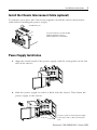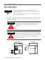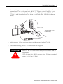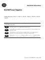
1
Installation Instructions
SLC 500 Power Supplies
Catalog Numbers 1746-P1, 1746-P2, 1746-P3, 1746-P4, 1746-P5, 1746-P6,
1746-P7
http://literature.rockwellautomation.com/idc/groups/literature/documents/in/
1746-in004_-mu-p.pdf
FR
Cette publication est disponible en français sous forme électronique (fichier PDF). Pour la
télécharger, rendez-vous sur la page Internet indiquée ci-dessus.
IT
Questa pubblicazione è disponibile in Italiano in formato PDF. Per scaricarla collegarsi al sito
Web indicato sopra.
DE
Diese Publikation ist als PDF auf Deutsch verfügbar. Gehen Sie auf die oben genannte
Web-Adresse, um nach der Publikation zu suchen und sie herunterzuladen.
JP
本書は PDF ファイルとして日本語でも公開しています。日本語版の閲覧お
よびダウンロードについては、上記のウェブアドレスをご参照下さい
Publication 1746-IN004B-EN-P - March 2008
2
Installation Instructions
Important User Information
Solid state equipment has operational characteristics differing from those of electromechanical equipment.
Safety Guidelines for the Application, Installation and Maintenance of Solid State Controls (publication
SGI-1.1 available from your local Rockwell Automation sales office or online at
http://literature.rockwellautomation.com) describes some important differences between solid state
equipment and hard-wired electromechanical devices. Because of this difference, and also because of the
wide variety of uses for solid state equipment, all persons responsible for applying this equipment must
satisfy themselves that each intended application of this equipment is acceptable.
In no event will Rockwell Automation, Inc. be responsible or liable for indirect or consequential damages
resulting from the use or application of this equipment.
The examples and diagrams in this manual are included solely for illustrative purposes. Because of the many
variables and requirements associated with any particular installation, Rockwell Automation, Inc. cannot
assume responsibility or liability for actual use based on the examples and diagrams.
No patent liability is assumed by Rockwell Automation, Inc. with respect to use of information, circuits,
equipment, or software described in this manual.
Reproduction of the contents of this manual, in whole or in part, without written permission of Rockwell
Automation, Inc., is prohibited.
Throughout this manual, when necessary, we use notes to make you aware of safety considerations.
WARNING
IMPORTANT
ATTENTION
Identifies information about practices or circumstances that can cause an explosion in
a hazardous environment, which may lead to personal injury or death, property
damage, or economic loss.
Identifies information that is critical for successful application and understanding of
the product.
Identifies information about practices or circumstances that can lead to personal injury
or death, property damage, or economic loss. Attentions help you to identify a hazard,
avoid a hazard, and recognize the consequences.
SHOCK HAZARD
Labels may be on or inside the equipment, for example, a drive or motor, to alert
people that dangerous voltage may be present.
BURN HAZARD
Labels may be on or inside the equipment, for example, a drive or motor, to alert
people that surfaces may reach dangerous temperatures.
Publication 1746-IN004B-EN-P - March 2008
Installation Instructions
SLC 500 Power Supplies
Catalog Numbers 1746-P1, 1746-P2, 1746-P3, 1746-P4, 1746-P5, 1746-P6,
1746-P7
Publication 1746-IN004B-EN-P - March 2008
4
Installation Instructions
ATTENTION
!
Environment and Enclosure
This equipment is intended for use in a Pollution Degree 2
industrial environment, in overvoltage Category II applications
(as defined in IEC publication 60664-1), at altitudes up to
2000 m (6561 ft) without derating.
This equipment is considered Group 1, Class A industrial
equipment according to IEC/CISPR Publication 11. Without
appropriate precautions, there may be potential difficulties
ensuring electromagnetic compatibility in other environments
due to conducted as well as radiated disturbance.
This equipment is supplied as open type equipment. It must be
mounted within an enclosure that is suitably designed for those
specific environmental conditions that will be present and
appropriately designed to prevent personal injury resulting from
accessibility to live parts. The interior of the enclosure must be
accessible only by the use of a tool. Subsequent sections of this
publication may contain additional information regarding
specific enclosure type ratings that are required to comply with
certain product safety certifications.
See NEMA Standards publication 250 and IEC publication
60529, as applicable, for explanations of the degrees of
protection provided by different types of enclosure. Also, see
the appropriate sections in this publication, as well as the
Allen-Bradley Industrial Automation Wiring and Grounding
Guidelines, publication 1770-4.1, for additional installation
requirements pertaining to this equipment.
Publication 1746-IN004B-EN-P - March 2008
Installation Instructions
5
Overview
Install your power supply using these installation instructions. The only tools you
require are flat head (1/8”) and Phillips head (1/4”, #2) screwdrivers.
ATTENTION
!
IMPORTANT
Electrostatic discharge can damage integrated circuits or
semiconductors if you touch backplane connector pins. Follow
these guidelines when you handle the power supplies.
•
•
•
•
•
Touch a grounded object to discharge static potential.
Do not touch the backplane connector or connector pins.
Do not touch circuit components inside the power supply.
Use a static-safe work station, if available.
Keep the power supplies in their static-shield packaging
when not in use.
If the equipment is not installed and used as described in this
manual, the protection provided by the equipment may be
impaired.
Hazardous Location Considerations
Products marked CL1, DIV 2, GP A, B, C, D are suitable for use in Class I, Division
2, Groups A, B, C, D or nonhazardous locations only. Each product is supplied with
markings on the rating nameplate indicating the hazardous location temperature
code. When combining products within a system, the most adverse temperature
code (lowest T number) may be used to help determine the overall temperature
code of the system. Combinations of equipment in your system are subject to
investigation by the local authority having jurisdiction at the time of installation.
WARNING
!
EXPLOSION HAZARD
• Do not disconnect equipment unless power has been
removed or the area is known to be nonhazardous.
• Do not disconnect connections to this equipment unless
power has been removed or the area is known to be
nonhazardous. Secure any external connections that mate
to this equipment using screws, sliding latches, threaded
connectors, or other means provided with this product.
• Substitution of components may impair suitability for Class
I, Division 2.
• All wiring must comply with N.E.C. article 501-4(b).
Publication 1746-IN004B-EN-P - March 2008
6
Installation Instructions
Environnements dangereux
Les produits marqués « CL 1, DIV 2, GP A, B, C, D » ne conviennent qu’à une
utilisation en environnements de Classe I, Division 2, Groupes A, B, C, D
dangereux et non dangereux. Chaque produit est livré avec des marquages sur sa
plaque d’identification qui indiquent le code de température pour les
environnements dangereux. Lorsque plusieurs produits sont combinés dans un
système, le code de température le plus défavorable (code de température le plus
faible) peut être utilisé pour déterminer le code de température global du système.
Les combinaisons d’équipements dans le système sont sujettes à inspection par les
autorités locales qualifiées au moment de l’installation.
WARNING
!
DANGER D’EXPLOSION
• Coupez l’alimentation ou vérifiez que l’environnement est
classé non dangereux avant de débrancher l’équipement.
• Coupez l’alimentation ou vérifiez que l’environnement est
classé non dangereux avant de débrancher les connecteurs.
Fixez tous les connecteurs externes reliés à cet équipement
à l’aide de vis, loquets coulissants, connecteurs filetés ou
autres moyens fournis avec ce produit.
• La substitution de composants peut rendre cet équipement
impropre à une utilisation en environnement de Classe I,
Division 2.
• Le câblage doit être conforme à l’article 501-4(b) du code
national de l’électricité aux Etats-Unis et aux
réglementations locales en vigueur.
Publication 1746-IN004B-EN-P - March 2008
Installation Instructions
7
Install the Chassis Interconnect Cable (optional)
To connect up to three SLC 500 chassis together, install the chassis interconnect
cable before installing the power supply.
SLC 500 Chassis/A
For more information, see the SLC 500
Modular Hardware Style User
Manual, publication 1747-UM011.
Power Supply Installation
1. Align the circuit board of the power supply with the card guides on the left
side of the chassis.
2. Slide the power supply in until it is flush with the chassis. Then fasten the
power supply to the chassis.
Use these screws to fasten the power supply
to the chassis with 1.2 Nm (11 lb-in) torque,
max.
Publication 1746-IN004B-EN-P - March 2008
8
Installation Instructions
Power Supply Wiring
For more information on wiring, see Allen-Bradley
Programmable Controller Grounding and Wiring Guidelines,
publication 1770-4.1.
TIP
Refer to publication 1746-IN016, for chassis installation and
grounding requirements.
1. Place the input voltage jumper to match the input voltage. (This does not
apply to the 1746-P3, 1746-P5, 1746-P6, and 1746-P7 power supplies, which
do not have a jumper.)
ATTENTION
!
WARNING
!
Set the input jumper before applying power. Hazardous
voltage is present on exposed pins when power is
applied; contact with the pin may cause injury to
personnel.
If you connect or disconnect the wiring to the terminal
blocks or if you insert or remove the power supply while
power is on, an electrical arc can occur. This could cause
an explosion in hazardous location installations. Be sure
that power is removed or the area is nonhazardous
before proceeding.
Catalog Numbers
1746-P1 & 1746-P2
Fuse
Catalog Number
1746-P4
Jumper Selection
85-132V ac
Jumper Selection
170-250V ac
100/120 Volts
200/240 Volts
Publication 1746-IN004B-EN-P - March 2008
Installation Instructions
9
2. Connect the ground screw of the power supply to the nearest ground or
ground bus. Use a 1.68 mm (#14 AWG) 75° Copper wire (Category 1 per
Industrial Automation Wiring and Grounding Guidelines, publication
1770-4.1) and keep the leads as short as possible. The 1746-P4 is shown
below.
Chassis Ground
Tighten terminal screws to
0.8 Nm (7 lb-in).
Nearest Ground Bus
3. Refer to page 11 for special wiring considerations for the 1746-P3.
4. Connect incoming power. See illustration on page 10.
ATTENTION
!
Turn off incoming power before connecting wires;
failure to do so could cause injury to personnel and/or
equipment.
Use 1.68 mm (#14 AWG) Copper wire. Tighten terminal
screws to 0.8 Nm (7 lb-in).
Publication 1746-IN004B-EN-P - March 2008
10
Installation Instructions
Catalog Number
1746-P3
Catalog Number
1746-P1 & P2
+ 24V dc
120/240V ac
Incoming
Power
VAC NEUT
Incoming
Power
Catalog Number
1746-P4
P4
Jumper
Selection
DC NEUT
CHASSIS GROUND
CHASSIS GROUND
Catalog Number
1746-P5
+125V dc
85–132V ac
Incoming
Power
JUMPER
DC NEUT
CHASSIS GROUND
170–250 V ac
P4
Incoming
Power
L1
85–132/170–250
L2
NEUTRAL
CHASSIS GROUND
Catalog Number
1746-P6
+48V dc
Incoming
Power
DC NEUT
CHASSIS GROUND
Catalog Number
1746-P7
+ 12/24V dc
Incoming
Power
DC NEUT
CHASSIS GROUND
ATTENTION
!
Your SLC 500 power supply can be damaged by voltage surges
when switching inductive loads such as motors, motor starters,
solenoids, and relays. To avoid damage to your SLC 500 power
supply in these applications, use an isolation transformer to
isolate the power supply from harmful voltage surges.
Publication 1746-IN004B-EN-P - March 2008
Installation Instructions
11
1746-P3 Wiring Considerations
This information describes special wiring considerations for the 1746-P3 power
supply that are not labeled as revision (REV) B.
Any voltage applied to the 1746-P3 DC NEUT terminal will be
present at the SLC logic ground and the processor DH-485 port.
To prevent unwanted potentials across the logic ground of the
controller and/or damage to the SLC chassis, the DC NEUTRAL
terminal of the external DC power source must be either
isolated from the SLC chassis ground or connected to earth
ground as shown in the following illustration.
ATTENTION
!
1746-P3
External DC Power Source
Processor
Door
DH-485
Port
DC Neut
DC Neut
Earth Ground
IMPORTANT
SLC Logic Ground
+24V dc
+24V dc
Chassis
Ground
SLC 500 Chassis
• A jumper wire is
recommended between
the DC NEUT and Chassis
Ground of the external
power source.
Earth
Ground
SLC 500 series A chassis (1746-A4, 1746-A7, 1746-A10, and
1746-A13) manufactured before November 1992 have a resistor
between the logic ground and chassis ground as the drawing on
the following page illustrates. This resistor could be damaged if
the wiring recommendation described within the attention box
above is not followed. See the figure on the following page for
the location of the resistor. SLC 500 series A chassis (1746-A4,
1746-A7, 1746-A10, and 1746-A13) with a manufacture date of
November 1992 or later do not have this resistor. SLC 500 series
B chassis have a 1 MΩ resistor that limits the current between
logic ground and chassis ground.
Publication 1746-IN004B-EN-P - March 2008
12
Installation Instructions
1746-P3
SLC 500 Chassis
Processor
Door
Not Used
Not Used
DH-485
Port
SLC Logic Ground
Resistor
+24V dc
•
•
DC Neut
Chassis
Ground
Chassis Ground
Earth
Ground
5. (Optional) For the 1746-P1, 1746-P2, 1746-P4, 1746-P5, and 1746-P6 power
supplies, use PWR OUT +24V dc and PWR OUT COM terminals to power
24V dc sensors and loads. The terminals on the 1746-P1, 1746-P2, 1746-P5,
and 1746-P6 power supplies provide an isolated, non-fused 200 mA, 24V dc
power supply. The terminals on the 1746-P4 power supply provide an
isolated, non-fused 1A, 24V dc power supply. (The 1746-P3 and 1746-P7
power supplies do not provide for an external power source.)
Catalog Number
1746-P1, 1746-P2, 1746-P5, & 1746-P6
User Power
Catalog Number
1746-P4
PWR OUT +24V dc
PWR OUT +24V dc
PWR OUT COM
Publication 1746-IN004B-EN-P - March 2008
User Power
PWR OUT COMMON
Installation Instructions
13
SLC 500 Operation with 24V dc User-power Overcurrent
Condition
Cat. No.
SLC Operation
Recovery Procedure
1746-P1 series A (made in Japan)
Power supply shutdown, CPU Fault
Reload user program
1746-P1 series A (made in Malaysiacurrent production)
24V dc user shutdown, CPU continues
Correct overcurrent condition
1746-P2 series A, B
Power supply shutdown, CPU Fault
Reload user program
1746-P2 series C
24V dc user shutdown, CPU continues
Correct overcurrent condition
1746-P4 series A
Power supply shutdown, CPU Fault
Reload user program
1746-P5 series A
24V dc user shutdown, CPU continues
Correct overcurrent condition
1746-P6 series A
24V dc user shutdown, CPU continues
Correct overcurrent condition
ATTENTION
!
For 1746-P1 (made in Malaysia), 1746-P2 series C, 1746-P5 series
A, and 1746-P6 series A power supplies, monitor the 24V dc
user output with a 24V dc input channel to avoid unexpected
operation due to 24V dc user power shutdown.
6. Remove the protective label.
Publication 1746-IN004B-EN-P - March 2008
14
Installation Instructions
Power Supply Undervoltage Operation
SLC 500 controllers continue to operate (hold-up) for a short period of time if the
input voltage to the power supply drops below the recommended operating
voltage range. The controller continues to scan the user program and control I/O
during this time. CPU hold-up for each power supply is shown on pages 14 and 16.
SLC 500 controllers turn OFF (stop scanning and disable outputs) if input voltage to
the power supply is removed or drops below the recommended operating range
for a period exceeding the CPU hold-up time. The controller resumes operation
automatically when the input voltage is restored to normal.
If the input voltage to the 1746-P7 power supply falls into a range of 4 to 9V for a
period exceeding the CPU hold-up time, the controller turns OFF and will not turn
back ON until input voltage is increased to 11V dc.
General Specifications (1746-P1, 1746-P2, 1746-P3, and 1746-P4)
Attribute
Value
1746-P3
1746-P4
Line voltage
85...132/170...265V ac
47...63 Hz
19.2...28.8V dc
85...132/
170...250V ac 47...63
Hz
Typical line power
requirement
135VA
180VA
90VA
150VA
Inrush current, max
20 A
Internal current
capacity
2 A at 5V dc
0.46 A at 24V dc
5 A at 5V dc
0.96 A at 24V dc
3.6 A at 5V dc
0.87 A at 24V dc
10.0 A at 5V dc
2.88 A at 24V dc(1)
Fuse protection(2)
1746-F1 or
equivalent(3) (4)
1746-F2 or
equivalent(3) (5)
1746-F3 or
equivalent(3) (6)
Fuse is soldered in
place.
24V dc user-power
current capacity
200 mA
Not applicable
1 A(1)
24V dc user-power
voltage range
18...30V dc
User-supplied
overcurrent
protection(7), max
15 A
Temperature,
ambient operating
0...60 °C (32...140 °F)
Current capacity is derated 5% above 55 °C (131 °F).
Isolation(8)
1800V ac RMS for 1 s
600V ac RMS for 1 s 2600V dc for 1 s
(version B or later)
CPU hold-up time(9)
20 ms (full load) 3000 ms (no load)
5 ms (full load)
1000 ms (no load)
1746-P1
1746-P2
45 A
Publication 1746-IN004B-EN-P - March 2008
20.4...27.6V dc
Not applicable
15 A
0...60 °C
(32...140 °F)
no derating
20 ms (full load)
3000 ms (no load)
Installation Instructions
Attribute
Value
1746-P1
Certification
(when product is
marked)
15
1746-P2
1746-P3
1746-P4
UL Listed Industrial Control Equipment for Class 1, Division 2,
Groups A, B, C, D Hazardous Locations
UL Listed Industrial
Control Equipment
C-UL Listed Industrial Control Equipment for Class 1, Division 2,
Groups A, B, C, D Hazardous Locations
CSA Certified
Process Control
Equipment for
Class 1, Div 2,
Groups A, B, C, D
Hazardous Locations
CE(10)
European Union 89/336/EEC EMC Directive, compliant with:
EN 50082-2 Industrial Immunity
EN50081-2 Industrial Emissions
European Union 73/23/EEC LVD Directive, compliant with:
EN61131-2 Programmable Controllers
C-Tick
Australian Radiocommunications Act, compliant with:
AS/NZS 2064 Industrial Emissions
(1)
The combination of all output power (5V backplane, 24V backplane, and 24V user source) cannot exceed 70 W.
(2)
Power supply fuse is intended to guard against fire hazard due to short-circuit conditions. This fuse may not protect the
supply from miswiring or excessive transient in the power line.
(3)
Fuse sizes specified are for end-devices only. Fuse size may need to be reduced depending on the size of circuit wiring.
(4)
Equivalent fuses: 250V-3A fuse, nagasawa ULCS-61ML-3, or BUSSMAN AGC 3.
(5)
Equivalent fuse: 250V-3A fuse, SANO SOC SD4, or BUSSMAN AGC 3.
(6)
Equivalent fuse: 125V-5A fuse, LITTLEFUSE 233.
(7)
Use time-delay type overcurrent protection in all ungrounded conductors.
(8)
Isolation is between input terminals and backplane.
(9)
CPU hold-up time is for 0V unless specified. Hold-up time is dependent on power supply loading.
(10) See the Product Certification link at http://ab.com for Declarations of Conformity, Certificates, and other certification
details.
Publication 1746-IN004B-EN-P - March 2008
16
Installation Instructions
General Specifications (1746-P5, 1746-P6, and 1746-P7)
Attribute
Value
1746-P5
1746-P6
1746-P7
Line voltage
90...146V dc
30...60V dc
10...30V dc(1)
Typical line power
requirement
85VA
100VA
12V dc input: 50VA
Inrush current, max 20 A
20 A (required for turn-on)
Internal current
capacity
12V dc input:
2.0 A at 5V dc
0.46 A at 24V dc
5 A at 5V dc
0.96 A at 24V dc
24V dc input: 75VA
24V dc input:
3.6 A at 5V dc
0.87 A at 24V dc
See 1746-P7 current capacity chart on page 17.
Fuse is soldered in place.
(2)
Fuse protection
24V dc user-power 200 mA
current capacity
Not applicable
24V dc user-power 18...30V dc
voltage range
Temperature,
operating ambient
0...60 °C (32...140 °F)
Current capacity is derated 5% above 55 °C (131 °F).
Isolation(3)
1800V ac RMS for 1 s
600V ac RMS for 1 s
CPU hold-up time
20 ms
(full load)
3000 ms (no
load)
12V dc input:
1.37 ms at 0V dc
(full load)
895 ms at 0V dc
(no load)
10 ms at 9V dc
(full load)
continuous at 9V dc
(no load)
Certification
(when product is
marked)
UL Listed Industrial Control Equipment for Class 1, Division 2,
Groups A, B, C, D Hazardous Locations
(4)
5 ms
(full load)
1500 ms (no
load)
24V dc input:
40 ms at 0V dc
(full load)
1860 ms at 0V dc
(no load)
790 ms at 11V dc
(full load)
continuous at 11V dc (no
load)
C-UL Listed Industrial Control Equipment for Class 1, Division 2,
Groups A, B, C, D Hazardous Locations
CE(5)
European Union 89/336/EEC EMC Directive, compliant with:
EN 50082-2 Industrial Immunity
EN50081-2 Industrial Emissions
European Union 73/23/EEC LVD Directive, compliant with:
EN61131-2 Programmable Controllers
C-Tick
Australian Radiocommunications Act, compliant with:
AS/NZS 2064 Industrial Emissions
(1)
See page 14 for information on power supply undervoltage operation.
(2)
Power supply fuse is intended to guard against fire hazard due to short-circuit conditions. This fuse may not protect the
supply from miswiring or excessive transient in the power line.
(3)
Isolation is between input terminals and backplane.
(4)
CPU hold-up time is for 0V unless specified. Hold-up time is dependent on power supply loading.
(5)
See the Product Certification link at http://ab.com for Declarations of Conformity, Certificates, and other certification
details.
Publication 1746-IN004B-EN-P - March 2008
Installation Instructions
17
1746-P7 Current Capacity
24V dc
Output Current
5V dc
Output Current
0.87 A
3.6 A
0.625 A
2.64 A
0.46 A
2.0 A
Input Voltage
10V dc
12.2V dc
19.2V dc
15V dc
30V dc
Physical Dimensions
Controller
Length, Approx.
mm (in.)
Depth, Approx.
mm (in.)
Height, Approx.
mm (in.)
1746-P1
65 (2.56)
140 (5.70)
140 (5.51)
1746-P2
85 (3.35)
1746-P3
1746-P4
110 (4.33)
145 (5.70)
1746-P5
85 (3.35)
140 (5.70)
1746-P6
1746-P7
Publication 1746-IN004B-EN-P - March 2008
18
Installation Instructions
Notes:
Publication 1746-IN004B-EN-P - March 2008
19
Notes:
Publication 1746-IN004B-EN-P - March 2008
Rockwell Automation Support
Rockwell Automation provides technical information on the Web to assist you in
using its products. At http://support.rockwellautomation.com, you can find
technical manuals, a knowledge base of FAQs, technical and application notes,
sample code and links to software service packs, and a MySupport feature that you
can customize to make the best use of these tools.
For an additional level of technical phone support for installation, configuration,
and troubleshooting, we offer TechConnect Support programs. For more
information, contact your local distributor or Rockwell Automation representative,
or visit http://support.rockwellautomation.com.
Installation Assistance
If you experience a problem with a hardware module within the first 24 hours of
installation, please review the information that's contained in this manual. You can
also contact a special Customer Support number for initial help in getting your
module up and running.
United States
1.440.646.3434
Monday – Friday, 8am – 5pm EST
Outside United
States
Please contact your local Rockwell Automation representative for any
technical support issues.
New Product Satisfaction Return
Rockwell tests all of its products to ensure that they are fully operational when
shipped from the manufacturing facility. However, if your product is not
functioning, it may need to be returned.
United States
Contact your distributor. You must provide a Customer Support case number
(see phone number above to obtain one) to your distributor in order to
complete the return process.
Outside United
States
Please contact your local Rockwell Automation representative for return
procedure.
Allen-Bradley, Rockwell Automation, TechConnect, SLC, and SLC 500 are trademarks of Rockwell Automation, Inc.
Trademarks not belonging to Rockwell Automation are the property of their respective companies.
Publication 1746-IN004B-EN-P - March 2008
Supersedes Publication 1746-IN004A-EN-P - September 2007
PN 40072-083-01(6)
Copyright © 2008 Rockwell Automation, Inc. All rights reserved. Printed in Malaysia.