1
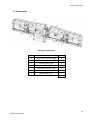
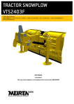
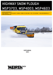
AIRPORT SNOW PLOUGH VLES6700, VLES7300 MEIREN ENGINEERING OÜ VÄIKE-MÄNNIKU 7 /// 11216 TALLINN /// ESTONIA /// TEL +372 682 5002 /// FAX +372 610 0589 /// E-MAIL [email protected] /// WWW.MEIRENSNOW.COM USER MANUAL 2015 This user manual applies to all snow ploughs from serial number 0891XXXXXX SNOW PLOUGH VLES CONTENTS CE DECLARATION OF CONFORMITY ..................................................................................................................... 3 FOREWORD ........................................................................................................................................................ 4 GENERAL SAFETY REGULATIONS ........................................................................................................................ 4 PERSONNEL ....................................................................................................................................................... 4 1. PRODUCT DESCRIPTION ............................................................................................................................. 5 1.1. 1.2. 2. INTEGRITY OF THE SNOW PLOUGH WITH STANDARD EQUIPMENT ................................................................................... 5 ACCESSORIES ..................................................................................................................................................... 5 SAFETY REGULATIONS FOR WORKING WITH THE PLOUGH ......................................................................... 6 2.1. 2.2. 3. BEFORE WORKING WITH THE PLOUGH ..................................................................................................................... 6 OPERATING THE SNOW PLOUGH ............................................................................................................................. 6 MOUNTING AND REMOVING THE PLOUGH .................................................................................................. 7 3.1 MOUNTING THE PLOUGH ON THE VEHICLE .................................................................................................................... 7 3.2 REMOVING THE PLOUGH FROM THE VEHICLE ................................................................................................................ 7 4. USING THE PLOUGH ................................................................................................................................... 7 4.1 4.2 4.3 4.4 5. PLOUGH CONTROL WITH HYDRAULIC ELECTRIC VALVES................................................................................................... 8 ADJUSTING RUBBER OR POLYURETHANE BLADES .......................................................................................................... 8 MOUNTING STEEL BLADES ........................................................................................................................................ 8 DESCRIPTION AND USE OF HARDOX RUBBER BLADES ..................................................................................................... 9 SNOW PLOUGH MAINTENANCE ................................................................................................................... 9 5.1 GREASE POINTS..................................................................................................................................................... 10 6. PRODUCT WARRANTY TERMS AND CONDITIONS ....................................................................................... 11 TABLES Table 1. Technical data for the plough ......................................................................................................................... 5 FIGURES Drawing 1. Safety marking: RISK OF ACCIDENT! .......................................................................................................... 7 Drawing 2. Hardox rubber blades .................................................................................................................................. 9 Drawing 3. Grease points ............................................................................................................................................. 10 2 WWW.MEIRENSNOW.COM SNOW PLOUGH VLES CE DECLARATION OF CONFORMITY Manufacturer: Meiren Engineering OÜ Väike- Männiku 7, 11216 Tallinn, Estonia Tel +372 682 5002 www.meiren.ee We declare that the below mentioned product Airport snow plough VLES Model: ............................................ Serial number: ............................................ Time of construction: ............................................ meets with the following directives and standards: 2006/42/EC EN 349:1993+A1:2008 3 WWW.MEIRENSNOW.COM SNOW PLOUGH VLES FOREWORD Thank you for choosing the Meiren Snow product. This user manual includes technical data, user manuals and instructions on maintenance and warranty terms and conditions for VLES snow ploughs. VLES series snow ploughs are manufactured to plough bigger loads of snow on wheel loaders. They are suited for use in parking lots, airports and other closed areas which have no obstacles higher than the road level. The product is not suitable for ploughing sand, gravel, caked snow, ice and the like. Unintended use of the plough may result in financial loss and cause bodily injuries. It is therefore essential that the person using the plough reads the manual and operates the product according to the requirements. Any misuse of the product releases the manufacturer from liability with respect to reimbursement of resulting damages and costs. GENERAL SAFETY REGULATIONS Because the product has a complex structure and moving parts, it is essential that the person who works with the device is acquainted with all safety risks. To alleviate the risks, it is important that the operator has familiarized himself with the user manual for the product; operator has passed a relevant training course which allows him to use this type of product for work; operator is equipped with necessary tools and wears appropriate work clothing. PERSONNEL This product may be used and maintained by trained staff only. The employer of the operator is obligated to ensure that all instruction manuals and safety regulations of the manufacturer are being followed. Carefully read the manual before working with the plough! 4 WWW.MEIRENSNOW.COM SNOW PLOUGH VLES 1. PRODUCT DESCRIPTION Airport snow plough VLES is a 4-section snow plough with up-to-date solutions. Middle sections can be rotated 35° in two directions, side sections can be rotated 90° to the front. The blades of the plough stand at 90° in relation to the ground. To protect the plough during impact with an obstacle, the plough is equipped with safety valves and a hydraulic system accumulator. This allows the flap of the plough to pull away if the cylinder is not in the final position towards the impact. It is possible to install both rubber and steel blades on the plough. It is possible to use both regular and special wedge bolts for quick replacement of the steel blade. Quick connection of rubber blades can be used for holding the wedge bolts during the replacement of steel blades. For this, the operator must press a 30-50 mm thick rubber band against the wedge bolts. In case the rubber blades are used simultaneously to the steel blades, there is no need to use the rubber band. The plough is manufactured using high-tempered steel. Polyurethane paint is used as a finishing agent, as it is more resistant to corrosion than regular paint. Model Total width of the plough flap blades, mm Working width of the plough flap at max rotary angle, mm Overall width of the plough flap, mm Maximum internal height of the plough flap (including rubber blades), mm Minimum internal height of the plough flap (including rubber blades), mm Max rotary angle of the plough (to both sides) Angle of the blades in relation to the road Width of the flap section Total mass of the plough (without blades and accessories), kg Recommended hydraulic working pressure, bar Recommended hydraulic pump output, l/min 6700 7300 6,690 7,300 5,525 6,025 6,890 7,500 1,200 1,200 1,063 1,063 35° 35° 90° 90° 2x1,525mm+ 2x 1,220mm+ 2x 2,135 mm 2x 2,135mm 2,250 2,309 140…180 30…50 Table 1. Technical data for the plough 1.1. Integrity of the snow plough with standard equipment Snow plough with pivot cylinders (4 pcs). Hoses without quick connection nozzles “¾” Safety marking (reflector films on the front and rear of the plough). Hydraulic impact protection valve for the pivot cylinder with a hydraulic system accumulator. Solenoid valves (hydraulic electric valves) 1.2. Accessories Set of steel blades. Set of polyurethane blades. Set of rubber blades 5 WWW.MEIRENSNOW.COM SNOW PLOUGH VLES 2. SAFETY REGULATIONS FOR WORKING WITH THE PLOUGH 2.1. Before working with the plough Check the integrity and the technical condition of the plough. It is not permitted to begin work with a device that is not in technically good condition. Check that there are no people or objects in the vicinity that the plough may harm. The safety of people must also be ensured during maintenance and repair works and while moving the plough with the help of hydraulics or some other lifting device. In the event of failure to adhere to the safety regulations, the plough may cause injuries (there is a safety marking on the plough, see figure 1), It is prohibited to work under a lifted plough if the plough is not supported. Check that the plough is firmly attached to the wheel loader and that the fastenings are not damaged. Check that the safety marking, position lamps (if applicable) and reflex reflectors are in order and visible. Check the condition of the blades. Worn-out blades must be positioned downwards, turned around or replaced, so as not to damage the blade holder. Do not place your hand or any other body part under the plough when adjusting the height of the blades. The engine of the wheel loader may not run when adjusting the blades. Check the fastening wedges of the blades. Check the fastening pins of the levers and cylinders. Check that the hydraulic hoses are sound and fastened correctly. Check that the plough has been thoroughly lubricated. Check that the plough is not damaged. 2.2. Operating the snow plough The plough may be operated by a person who is at least 18 years old, has a driver’s license for the relevant category and has familiarized oneself with the user manual for the snow plough. Always be aware of your surroundings and other traffic, including vehicles approaching from side roads and behind you. Be mindful of pedestrians and cyclists so that you do not put them in danger while operating the snow plough. All warning lights must be switched on while operating the snow plough! Observe the general traffic regulations. The maximum permitted working speed for the plough under normal road conditions is 60 km/h. Be mindful of the road conditions: reduce speed during thaw, observe the wind direction in case of powder snow and reduce speed if necessary. The plough may only be used to push loose snow! It is prohibited to plough ice, frozen snowdrifts, stones, gravel, sand, etc. If the plough is used on uneven roads where it is possible to damage the plough, the vehicle and road surface, the responsibility falls on the operator. Damages resulting from such behavior shall not be reimbursed. It is not permitted to mount accessories that do not have the approval of the manufacturer on the moving parts of the plough. It is prohibited to use hydraulically operated devices as levers. The plough may only be raised from the lifting eyes. Every time something happens during working with the plough that could damage the device, a device inspection shall be organized to establish and assess potential impairments. Damages (cracks in the structure or welding, deformed details) may danger property and people’s health. It is prohibited to continue operating the device, unless the damages have been repaired. 6 WWW.MEIRENSNOW.COM SNOW PLOUGH VLES Drawing 1. Safety marking: RISK OF ACCIDENT! 3. MOUNTING AND REMOVING THE PLOUGH 3.1 Mounting the plough on the vehicle The plough must be mounted on the vehicle on even ground. Drive the vehicle as close to the plough as possible and connect the hydraulic hoses to the vehicle’s hydraulics. Lead the vehicle’s mounting plate against the centre frame of the plough. Check that the retaining rings are in the right position, then lock the centre frame of the plough to the vehicle’s mounting plate (different locking systems are used in different countries – follow the prescribed system). 3.2 Removing the plough from the vehicle Place the plough on even ground, with the blade on the ground. Disconnect the plough’s centre frame from the mounting plate of the vehicle. Disconnect the hoses and drive away. 4. USING THE PLOUGH It is essential to choose the correct working methods so as not to overload the plough. For ploughing thick and heavy snow choose the appropriate (slow) driving speed and be constantly mindful of the consistency of snow. While driving the plough, lift it at least 300 mm from the ground. Carefully follow the safety regulations. When you have finished working with the plough always support the plough on the ground. The plough is equipped with a fastening provided by the client (generally Volvo BM fastening), and mounting is carried out similarly to mounting a shovel loader or any other device used by the client. Additionally, the operator must connect the hydraulic quick connection nozzles and the plug connector for the valve control. 7 WWW.MEIRENSNOW.COM SNOW PLOUGH VLES 4.1 Plough control with hydraulic electric valves Valves are controlled with two 3-position switches. The first switch controls the hydraulic valve, which in turn controls the movement of flap sections on the sides of the plough. The second switch controls the hydraulic valve, which in turn controls the movement of flap sections in the centre of the plough. Switches are not included in the plough set. The first switch in position „0”, the second switch in position „0”. A synchronized movement of the flaps of the plough is carried out. The direction depends on which quick connection nozzles are being hydraulically pressurized. The first switch in position „0”, the second switch in the „left” position. Movement of the left flap of the middle section of the plough is carried out. The direction depends on which quick connection nozzles are being hydraulically pressurized. The first switch in position „0”, the second switch in the „right” position. Movement of the right flap of the middle section of the plough is carried out. The direction depends on which quick connection nozzles are being hydraulically pressurized. The first switch in position „left”, the second switch in position „0”. Movement of the left flap of the side section of the plough is carried out. The direction depends on which quick connection nozzles are being hydraulically pressurized. The first switch in position „right”, the second switch in position „0”. Movement of the right flap of the middle section of the plough is carried out. The direction depends on which quick connection nozzles are being hydraulically pressurized. NB! One of the two switches must always be in position „0”. 4.2 Adjusting rubber or polyurethane blades Lift the plough off the ground to the height you wish to adjust the rubber or polyurethane blades downward. Loosen the fastening bolts of the blade holders (the centre sections have 3 bolts on each side and the side sections have 2 bolts) and lower the rubber or polyurethane blades to the ground. The bolts should be loosened until the rubber or polyurethane is adjustable. Then tighten the fastening bolts of the blade holders. 40-60 mm rubber or polyurethane blades may be used. The height of the rubber or polyurethane blades is 200 mm. Rubber or polyurethane blade is usually used to plough sleet. 4.3 Mounting steel blades Regular bolts (with nut) as well as special wedge bolts may be used to mount steel blades. To fasten the bolts, the rubber blades must be removed. To adjust the height of the steel blades, the wedges must be knocked out (in case of a regular bolt, the nut must be loosened) and the steel blades set one level lower. Then knock the wedges back in (in case of a regular bolt, tighten the nut). If wedge bolts are used, the rubber blades must not be unfastened while adjusting or mounting the steel blade, since the rubber blade supports the wedge bolt. The blades must be placed in front of the plough flap. Blades with distance between mounting holes of 305 mm can be used. Steel blade is used to push packed snow or ice (preferably net blade). In this case, also use a rubber or polyurethane blade. 8 WWW.MEIRENSNOW.COM SNOW PLOUGH VLES 4.4 Description and use of Hardox rubber blades Hardox rubber blades are highly durable rubber blades with Hardox metal reinforcement that withstand difficult conditions better than standard rubber blades and ensure significantly longer lifetime thanks to wear resistant metal. Hardox blade is suitable for use instead of rubber blade with all snowploughs. Hardox rubber blade includes steel blade segments surrounded by rubber. Hardox rubber blade can be used on both sides up to the red area marked on the blade. If one side of the blade is worn out up to the red area, turn the blade over and use the other side until it reaches the red area. Hardox rubber blade wear must not exceed the red line, i.e. 70 mm on both sides. Drawing 2. Hardox rubber blades 5. SNOW PLOUGH MAINTENANCE MAINTENANCE AFTER 8 WORKING HOURS MAINTENANCE EFTER EVERY 150 WORKING HOURS Check all the bolt connections and hydraulic connections, tighten them if necessary. In case of wheels, check the wheel bearing slack. In the event that there is too much slack, pull out the wheel hub, check the bearings and adjust the slack (there is a nut in the hub and a lock washer with special tabs for adjustment). Check all the bolt connections and hydraulic connections, tighten them if necessary. Lubricate all lubrication areas: include rotary and lifting bearings of the flap, parallelogram bearings, also the mounting frame bearing in case of confirmation from Norway and Denmark. Lubricate the adjustment mechanism in case of sliding soleplates and wheels. Check the condition of the blades and fastenings. If necessary, adjust or replace the blades. Check that the hydraulic system does not have any leaks. If necessary, tighten the hydraulic fittings and hose ends. Check the condition of the blades and fastenings. If necessary, adjust or replace the blades. X X X X X X X X X SEASONAL MAINTENANCE Check all the bolt connections and hydraulic connections, tighten them if necessary. Check that the hydraulic system does not have any leaks. If necessary, tighten the hydraulic fittings and hose ends. Spray the zinc parts, hydraulic valves and the ends of hoses of the plough with preservative wax. Lubricate all lubrication areas. Cover the protruding adjustment areas of the inner tube wheel mechanism and support wheels with grease or wax. Check the snow plough visually and identify whether there are parts that need replacing. Repair any paint damage. Pull in the cylinder piston rod or preserve it with appropriate grease. Let the plough be open to winds, but protect it from rain and sun. 9 WWW.MEIRENSNOW.COM SNOW PLOUGH VLES 5.1 Grease points Drawing 3. Grease points Pos. no 1 2 3 4 5 6 7 Location Right rotation cylinder, large Right rotation cylinder, small Mounting ears, right Centre flap Left rotation cylinder, large Left rotation cylinder, small Mounting ears, left In all Quantity 2 2 2 3 2 2 2 15 10 WWW.MEIRENSNOW.COM SNOW PLOUGH VLES 6. PRODUCT WARRANTY TERMS AND CONDITIONS The seller shall give the product a warranty period of 12 (twelve) months. The warranty period shall begin when the product is transferred to the purchaser, the delivery time shall be the date specified on the instrument of delivery and receipt or the CMR consignment note. The warranty shall cover the elimination of discovered manufacturing, material or structural defects of the product by the seller. The seller shall be obligated to replace the defective product with a new one only if the product or its component parts cannot be repaired or the detail cannot be replaced. The purchaser shall agree to notify the seller in writing within 7 (seven) calendar days of becoming aware of the defect, describing the defect with sufficient accuracy. The seller shall be required to carry out an expert analysis to identify the causes of the defect within fourteen (14) business days after the purchaser’s written notice of the warranty case. If the cause is covered by the warranty, the seller shall eliminate it within 20 (twenty) working days after the expert analysis is carried out. Warranty repairs shall be carried out at the shipping address specified in the order confirmation. Repair work of larger scale shall be carried out in the territory of the seller. Cost of transporting the product for warranty repair shall be paid by the purchaser. The purchaser shall cover the expenses and transport costs for repair works excluded from the warranty terms and conditions. Warranty shall not cover defects which are caused: – as a result of natural wear and tear of the product; – as a result of road surface characteristics or damage thereof; – in connection with the use of the product contrary to the technical requirements, safety regulations and intended purpose; – due to failure to observe the maintenance requirements of the product; – due to a traffic accident; – of which the purchaser has not notified the seller in writing within 7 (seven) days following its occurrence, and / or the purchaser has not given the seller an opportunity to determine the cause of the defect pursuant to the contract; – in the extent to which the increasing of the defect could have reasonably been prevented by the seller. Product warranty shall expire prematurely from the time when: – the product is repaired independently without acquiring a prior written approval from the seller; – the design is changed, additional equipment and / or spare parts have been installed independently without acquiring a prior written approval from the seller. In the event that the seller, despite repeated written appeal from the purchaser, fails to fulfil its warranty obligations under the contract, the purchaser shall have the right to repair the product at the cost of the seller. The purchaser must notify the seller in writing at least (5) five business days prior to the replacement or repair of the defective product, and provide a reasonable estimation of the expected cost. The purchaser may withdraw from the contract and demand the collection of the product and refund only in the event that there is a defect which cannot be repaired or a part which cannot be replaced, and the replacement of the defective product with a new product would also not give results which would allow using the product as intended. The warranty for the product or its part replaced during the warranty period shall cover the product or its part until the end of the general warranty period. 11 WWW.MEIRENSNOW.COM