1
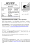
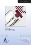
Train Simulator 2015 West Highland Line Extension Fort William to Mallaig 1 ROUTE INFORMATION ................................................................................................... 3 1.1 Fort William to Mallaig ..................................................................................................................... 3 1.2 The Road to the Isles ...................................................................................................................... 4 1.3 The West Highland to Spean Bridge ................................................................................................ 5 1.4 Rolling Stock .................................................................................................................................... 5 1.5 Focus Time Period ............................................................................................................................ 6 2 THE CLASS 37/4 LOCOMOTIVE ..................................................................................... 7 2.1 Locomotive History .......................................................................................................................... 7 2.2 Design & Specification ..................................................................................................................... 8 2.3 Cabin Controls .................................................................................................................................. 8 2.4 Regulator Operation ....................................................................................................................... 11 2.5 Train Brake Operation .................................................................................................................... 11 2.6 Automatic Warning System Self-test (AWS) .................................................................................. 12 2.7 Driver Safety Device and Vigilance System (DSD/DVD) ................................................................ 12 2.8 Non-standard Keyboard Controls ................................................................................................... 12 2.9 Game Controller and HUD Control of RETB Radio ......................................................................... 12 2.10 Scenario Editor – Locomotive Numbering Scheme ...................................................................... 13 © Copyright Thomson Interactive Ltd, all rights reserved Release Version 1.0 Train Simulator 2015 – West Highland Line Extension 2.11 Tutorial Scenario – Where is it? .................................................................................................. 13 3 RADIO ELECTRONIC TOKEN BLOCK (RETB)................................................................ 14 3.1 System History and Overview ........................................................................................................ 14 3.2 Typical Token Exchange Point Layout ........................................................................................... 15 4 QUICK DRIVE ................................................................................................................. 16 4.1 RETB Simplification ........................................................................................................................ 16 4.2 Speed Boards and the HUD ............................................................................................................ 16 4.3 Valid Quick Drive Journeys ............................................................................................................ 16 5 MANUAL LEVER FRAMES ............................................................................................... 17 6 SIGNALS ......................................................................................................................... 18 6.1 Main Signal Head Aspects .............................................................................................................. 18 6.2 Theatre Type Signals ..................................................................................................................... 18 6.3 “Call-on” Aspect ............................................................................................................................. 18 6.4 Ground Signals and Position Light Signals .................................................................................... 19 6.5 Repeater Signals ............................................................................................................................ 19 6.6 Semaphore Signals ......................................................................................................................... 20 6.7 Semaphore Signal FW24 ................................................................................................................ 21 6.8 Fixed Distant Signal Boards ........................................................................................................... 22 6.9 Level Crossing Warning Signs ........................................................................................................ 22 7 WHISTLE / WARNING HORN SIGNS ............................................................................ 23 8 SPEED SIGNS ................................................................................................................. 24 8.1 Permissible Speed Indicators ......................................................................................................... 24 8.2 Permissible Speed Warning Indicators .......................................................................................... 24 8.3 “MU” Speed Indicators ................................................................................................................... 24 8.4 Temporary Speed Restrictions ....................................................................................................... 25 9 SAFETY SYSTEMS ........................................................................................................... 26 9.1 AWS (Automatic Warning System) ................................................................................................. 26 9.2 TPWS (Train Protection and Warning System) – General Overview ............................................. 27 9.3 TPWS – West Highland Line Extension Notes ................................................................................ 27 10 PROCEDURAL FLORA ................................................................................................... 28 11 CONTENT CREATORS - TERMS AND CONDITIONS ................................................... 29 11.1 End User License Agreement (EULA) ........................................................................................... 29 11.2 Commercial Add-ons and Scenario Packs .................................................................................... 29 11.3 Workshop Scenarios ..................................................................................................................... 29 12 ACKNOWLEDGEMENTS ................................................................................................ 30 © Copyright Thomson Interactive Ltd, all rights reserved Page 2 Release Version 1.0 Train Simulator 2015 – West Highland Line Extension 1 Route Information 1.1 Fort William to Mallaig 'The Greatest Railway Journey in the World' - this is how travellers from around the globe have described the 41 miles of line from Fort William to the small fishing port of Mallaig on Scotland's northwest coast. The West Highland Railway from Glasgow to Fort William was opened by the North British Railway in 1894 but it did not provide a direct link to the Atlantic coast and its rich fishing grounds. In order to fulfil that potential, the extension of the route to the port of Mallaig was approved by 1896 and the challenging construction project completed just 4 years later. The building of the line would involve carving a path alongside lochs, bisecting rocky mountainous terrain and crossing deep glens and ravines. Through the pioneering use of in-situ concrete in the formation of the line's bridges, viaducts and tunnels, Glasgow contractor Robert 'Concrete Bob' McAlpine would become world famous in his field. The route boasts 11 tunnels and 8 major bridge structures including the iconic 21 arch span Glenfinnan Viaduct and Borrodale Viaduct, at the time of construction, the world's longest single span concrete arch at 124 feet. McAlpine's innovative methods would enable him to deliver the route a full year ahead of schedule. The completed line transformed travel in this corner of the Highlands, opening up new opportunities for tourism and providing a strong link to new markets for the fish catches landed by the Mallaig fleet. Until relatively recently the railway offered the fastest and most reliable link to the south, the only alternative connection being via a tortuous, predominantly single track road. This is one factor which has meant that the route has never been under any real threat of closure in spite of its lack of profitability over the years. Today the line thrives as a tourist attraction. Steam hauled tourist trains operate two daily return trips between Fort William and Mallaig through the summer. With its world beating scenery and global exposure through a number of blockbuster movies, the West Highland Line Extension has topped the list of World's most scenic railway journeys in recent years. Everyday operation on the route comprises a limited number of passenger services to and from Glasgow Queen Street, formed by Class 156 DMUs. Motive power on the route has been diverse over the last 100 years; NBR and LNER steam classes built specifically for the line operated into the 1960s, giving way to type 2 diesel hydraulic and diesel electric classes. The 1980s brought the much loved Class 37 locomotive to the West Highlands. While the trains operating on the line may have changed over the years, the infrastructure has remained largely unaltered. Concrete Bob's constructions have managed to withstand all that this harsh environment has unleashed and the single line track layout exists more or less as built, with only the harbour spur at Mallaig being truncated in the 1960s. One aspect which has undergone significant modernisation is the signalling of the route. The NBR's original semaphore signalling was replaced in 1987 by Radio Electronic Token Block (RETB) signalling. The system covers the entire West Highland Line as far as Helensburgh and is controlled from the purpose built signalling centre at Banavie. Only the Fort William area is controlled by conventional signals, a combination of colour light and semaphore, from the original signal box at Mallaig Junction. © Copyright Thomson Interactive Ltd, all rights reserved Page 3 Release Version 1.0 Train Simulator 2015 – West Highland Line Extension 1.2 The Road to the Isles Our journey west begins at the somewhat utilitarian terminus that is Fort William Station. The original NBR station was situated closer to the town centre on the edge of Loch Linnhe but it was relocated in 1975 to make way for a new bypass road. Departure is eastbound along the West Highland proper until we reach Mallaig Junction where the Mallaig Extension diverges to the north. With Ben Nevis towering behind us, the line passes the yard sidings and small servicing depot at Inverlochy. Once over the River Lochy on the lattice viaduct of the same name the line runs across the flat plain at the head of Loch Linnhe towards Banavie. The Signalling Centre dominates the platform at the station; beyond is Banavie Swing Bridge which carries the railway over the Caledonian Canal; the multiple locks of Neptune's Staircase can be seen lifting the canal some 20m as it heads east through the Great Glen towards Loch Ness. The sprawl of development on this relatively level area continues as Banavie gives way to Corpach. The station at Corpach is located adjacent to the lock and basin which separates the Caledonian Canal from the sea loch, Loch Linnhe. On departure, the tracks cling to the side of the loch between the station and the former pulp and paper mill site at Annat. Now a timber processing plant, the site retains some sidings which have become rather overgrown. Beyond Corpach is Loch Eil, the railway follows the lochside for its entire length, flanked by the A830 road. Loch Eil Outward Bound is the next station, a popular halt for those in search of activities on or near the loch. Towards the head of the loch is Locheilside Station, a request stop serving the small community of Kinlocheil. After 10 miles of near straight, level running the character of the alignment becomes more curvaceous and we tackle the first steep climb towards Glenfinnan. As any aspiring wizard will know, the spectacular Glenfinnan Viaduct forms part of a horseshoe curve that follows the contours of the steep mountains either side of the glen at the head of Loch Shiel. From atop the 100 foot high spans of the bridge there are dramatic views across the glen toward the Glenfinnan Monument to the Jacobite rebellion and beyond to Loch Shiel. Glenfinnan Station follows as the track continues to climb at a 1 in 50 gradient. The Victorian station building and signal box are typical of the larger stations on the line and are now home to a museum dedicated to local history the story of this iconic route. © Copyright Thomson Interactive Ltd, all rights reserved Page 4 Release Version 1.0 Train Simulator 2015 – West Highland Line Extension Between Glenfinnan and Loch Eilt the 361 foot summit of the line is reached. Descent to the west is rapid beyond the pair of tunnels above Loch Eilt. The track skirts the loch for most of its length, with Loch Eilt's scattering of mysterious pine covered islets almost within touching distance of the train. The loch drains into the River Ailort which we follow the short distance to Lochailort Station perched over the loch of the same name. Beyond Lochailort Station and Tunnel there is a short climb to Polnish. A pair of tunnels are followed by a glimpse of the striking Polnish Chapel, then the railway begins to drop back down towards sea level at Loch nan Uamh. The combination of sea views, sturdy viaduct and dramatic tunnels make this section of the route perhaps the most awe inspiring. The seven arch viaduct spanning Gleann Mama marks the start of Beasdale Bank, 2 miles of 1 in 48. The request stop at Beasdale is situated close to the top of the bank. After the 350 yard Borrodale Tunnel and then Viaduct, the line drops to Arisaig. This is Britain's most westerly station and offers spectacular panoramic views over the Atlantic coast to the islands of Eigg, Muck and Rum. After a further descent the alignment straightens for a level run across open moorland towards Morar. Morar Viaduct crosses the falls on the River Morar, Britain's shortest river, linking Loch Morar, Britain's deepest loch, to the sea. The silver sands and clear waters of this part of the coast can be glimpsed from Morar Station's single platform. On leaving the station there is only a short winding section of line inland before we arrive directly onto the rocky coastline just south of Mallaig. Our destination is reached and we are welcomed by the sounds of the sea and seagulls. Mallaig is a small but important harbour. Ferries from here link the mainland with the 'small isles' and the Isle of Skye which dominates the horizon to the northwest. Fishing activity is much reduced compared to that when the railway came to the village. Today it is the railway that generates activity, when the tourists alight and go forth on their search for a good plate of haddock and chips. 1.3 The West Highland to Spean Bridge Returning to Mallaig Junction, the West Highland Line continues in an easterly direction along the foot of Ben Nevis, Britain's highest mountain, bound for Spean Bridge and the south. On the outskirts of Fort William the former British Alcan aluminium smelter nestles in woodland in the shadow of Ben Nevis. The smelter is the UK's last surviving aluminium manufacturer and still generates a good flow of freight for the railway. The site has a number of sidings with a connection to the West Highland Line at Lochaber Junction. Between Fort William and Spean Bridge the landscape is more lowland in character, the railway cuts through the farmland and forestry of The Great Glen. The route running parallel with the main road to Inverness. 8 miles from Fort William, Spean Bridge Station is a beautifully preserved example of North British Railway architecture. The signal box dating from the 1940s remains intact but out of use. Beyond Spean Bridge the line continues due east towards Tulloch where it turns sharply south as it heads towards Glasgow. 1.4 Rolling Stock This route add-on includes our new Class 37/4 locomotive, Mk1 FK, SK and RMB coaches in both British Rail blue and grey livery and ScotRail West Highland green and cream livery. Mk3 BR blue and grey sleeper coaches are provided along with the following wagon types: OTA Timber Carrier OAA Open Wagons TTA Oil Tank Wagons PCA Alumina Wagons YGH “Sealion” Ballast Wagons © Copyright Thomson Interactive Ltd, all rights reserved Page 5 Release Version 1.0 Train Simulator 2015 – West Highland Line Extension 1.5 Focus Time Period The scenarios included with this route are set in the years between 1987 and 1989 when the Class 37/4 locomotives were the main traction type used on the route. However the route itself has been modelled in a more general time frame making it suitable for all traction types and DLC available. © Copyright Thomson Interactive Ltd, all rights reserved Page 6 Release Version 1.0 Train Simulator 2015 – West Highland Line Extension 2 The Class 37/4 Locomotive 2.1 Locomotive History For such an iconic route we needed an iconic train, and we think the Class 37/4 Locomotive was the ultimate traction in the West Highlands. During 1985 and 1986 a Class 37 refurbishment programme was underway in Crewe Works. Standard refurbishment work included receiving re-geared CP7 bogies and the English Electric generators were replaced with alternators. Thirty one of the re-built locomotives were also fitted with ETH (Electric Train Heating) supply. Twenty five of these re-classified 37/4 locomotives were allocated to Scottish depots Eastfield (ED) and Inverness (IS); the remaining six were allocated to Wales. The large logo BR Blue livery was applied to the whole 37/4 fleet with most of the Scottish examples receiving nameplates. Our new Class 37 model features: Completely new exterior model Unique simulated power and braking performance Sounds recorded from the real locomotive Automatic seasonal fitting of snowploughs Snow dynamically cleared from snowdrifts on the route Accurate logos and 3D nameplates automatically applied to all 25 Scottish locomotives Operating exterior fuel tank gauges Dynamically animated cooling fan Individual opening cabin doors separate in each cabin visible externally and internally Individual opening cabin windows separate in each cabin visible externally and internally Individual movable cabin visors separate in each cabin visible externally and internally 4 Individually selectable wipers in each cabin animated externally and internally 2 individually controlled cabin lights visible externally and internally Instrumentation lighting Instrumentation dimming Hotplate for warming your lentil soup! Fire alarm test Functional cabin radio and RETB CDU Two tone horn Eight cabin camera positions to select your preferred driving position © Copyright Thomson Interactive Ltd, all rights reserved Page 7 Release Version 1.0 Train Simulator 2015 – West Highland Line Extension 2.2 Design & Specification TOPS Number Range Refurbished by Weight Length Width Engine Type Power at Rail Max Speed Fuel Capacity Brake Types Class 37401 - 37431 BREL Crewe Works 107 tonnes 61ft 6in (18.74m) 8ft 11 5/8 th in (2.73m) English Electric 12CSVT 1,254hp (935kW) 80mph (128km/h) 1,670 gallons (7,592 litres) Air and Vacuum 2.3 Cabin Controls 1 2 3 4 5 6 7 8 9 10 11 12 13 14 15 16 17 18 19 20 21 22 23 24 25 26 27 Reverser Regulator (Throttle) Straight Air Brake Valve (Loco Only Brake) Train Brake with “Push Release” Position Engine Start Engine Stop Sander AWS Indicator (Sunflower Display) AWS Reset Driver’s Wiper Control Driver’s Wiper Motor and Manual Adjuster TPWS Panel and “Brake Demand” Lamp Ammeter in kA Speedometer in Mile/h Brake Pipe Gauge in Bar Vacuum Brake Gauges in Hg Brake Cylinder Pressure Gauges in lb/in 2 Main Reservoir Pressure Gauge in lb/in 2 Fault Panel (See items 50 and 51) Instrument Lamps Dimmer Head, Tail, Cabin and Instrument Lights Driver’s Glare Visor Driver’s Opening Window Driver’s Opening Door Cabin Radio (See items 37–40) RETB Cabin Display Unit (see items 41–45) Electric Train Supply Controls 28 29 30 31 32 33 34 35 36 37 38 39 40 41 42 43 44 45 46 47 48 49 50 51 52 53 Electric Train Supply Indicator Hotplate Control Second Man’s Horn Control Second Man’s Wiper Motor and Adjuster Second Man’s Wiper Control Handbrake Drivers Safety Device (Push-in to Enable) Second Man’s Opening Window Second Man’s Glare Visor Cabin Radio Power Button Cabin Radio Volume Control Cabin Radio Make Call Button Cabin Radio Tune (Push and Hold to tune) RETB CDU Send Button RETB CDU Receive Button RETB CDU Dim Display Button RETB CDU Current Token Type Display RETB CDU Current Token ID Display Second Man’s Opening Door Brake Mode Display Panel Brake Mode Selector Switch Fire Alarm Test Wheelslip Indicator Lamp Engine Stopped Indicator Lamp Driver’s Horn Control Drivers Safety Device Reset Pedal Refer to the following illustrations on pages 9 and 10. © Copyright Thomson Interactive Ltd, all rights reserved Page 8 Release Version 1.0 Train Simulator 2015 – West Highland Line Extension © Copyright Thomson Interactive Ltd, all rights reserved Page 9 Release Version 1.0 Train Simulator 2015 – West Highland Line Extension © Copyright Thomson Interactive Ltd, all rights reserved Page 10 Release Version 1.0 Train Simulator 2015 – West Highland Line Extension 2.4 Regulator Operation The Regulator (throttle lever) only applies power when the lever is moved beyond 20%. 2.5 Train Brake Operation To release the Train Brake you must push and hold the Train Brake lever or HUD control fully to the “Release” position. The Train Brake lever is sprung and will automatically return to the “Running” position. After an Emergency Brake application it can take more than 20 seconds to release the Train Brakes using this procedure. © Copyright Thomson Interactive Ltd, all rights reserved Page 11 Release Version 1.0 Train Simulator 2015 – West Highland Line Extension 2.6 Automatic Warning System Self-test (AWS) When the reverser has been moved from OFF to ENG ONLY, the automatic warning system self-test will commence. This is an audible continuous horn which is cancelled by pressing the AWS Reset button or “Q” on the keyboard. 2.7 Driver Safety Device and Vigilance System (DSD/DVD) The Driver Vigilance System ensures that the driver is conscious, is fully aware and able to respond quickly to alerts. After a period of approximately one minute, a buzzer will sound if the main controls have not been moved. If the controls are moved, the timer will be reset and the buzzer will not sound for an additional minute. When the buzzer does sound you must promptly press “E” or click on the Driver Safety Device pedal situated beneath the driving desk within 5 seconds. Failing to do so will result in an emergency brake application. The Driver Vigilance Device is automatically paused when viewing the train externally as to prevent accidental penalties. The Driver Vigilance Device is disabled by default, to enable it push down the button labelled “DSD Hold Over Switch” on the right hand side of the locomotive cabin (as illustrated here) or press SHIFT+E once to toggle the system on and off. 2.8 Non-standard Keyboard Controls SHIFT + V E SHIFT + E L M B Z CTRL + Z / Second Man’s Wiper DSD Pedal Toggle Vigilance System Toggle Cab Lights Toggle Instrument Lights Horn (High Note) Engine Start Engine Stop Toggle Handbrake F8 CTRL CTRL CTRL CTRL + + + + 1 2 3 4 (Hold) Toggle Radio Notifications RETB CDU Send RETB CDU Receive Radio Auto Tune Radio Make Call 2.9 Game Controller and HUD Control of RETB Radio If you do not have a mouse or keyboard attached to your computer and wish to interact with the RETB Radio features, then sound the Horn instead of the Radio Control needed. Remember to press and hold the Horn if you need to tune the radio frequency until tuning is complete. This alternative method will function either on the HUD or on a connected Microsoft Xbox 360 USB Controller. © Copyright Thomson Interactive Ltd, all rights reserved Page 12 Release Version 1.0 Train Simulator 2015 – West Highland Line Extension 2.10 Scenario Editor – Locomotive Numbering Scheme To use the new Class 37/4 locomotive in a scenario for a different route you will need to enable it in the object set filters editor menu, which will add it to the rolling stock list. Follow these steps: 1. Enter the Scenario Editor. (Note: If a route is locked it will need to be unlocked first before you can enter the Scenario Editor. Unlock by clicking the padlock icon in the bottom right of the screen). 2. Click the Object Set Filter button (the small blue cube on the middle left panel). 3. In the new window which opens on the right hand side, select the following: Thomson / FortWilliamMallaig 4. The Class 37/4, coaches and wagons will now appear in the list of rolling stock for that route. When placing a locomotive on another route a running number will automatically be assigned to it. In the locomotive properties dialog box in the scenario editor you will see additional numbers after the visible running number. As an example, a running number of 37425112309999 can be broken down like this: 37425 = (Actual Locomotive Number) 1 = (NRN Radio Mode) – This is the only option for other routes 123 = (Radio Frequency of 123 shown on Cabin Radio) 09999 = (Must be used for other routes) It is important if changing a running number to use the format above and ensure the correct numbers of digits are entered. The correct 3D Nameplates, logos and depot stickers will be applied automatically to locomotives 37401 – 37425 (Scottish allocated locos) 2.11 Tutorial Scenario – Where is it? We have included a short tutorial scenario that guides you through the operation of the Class 37/4 locomotive and the RETB Radio System. All tutorials are now accessible from the “Academy” section on the main menu. © Copyright Thomson Interactive Ltd, all rights reserved Page 13 Release Version 1.0 Train Simulator 2015 – West Highland Line Extension 3 Radio Electronic Token Block (RETB) 3.1 System History and Overview The route and the included Class 37 Locomotive feature a version of the RETB system. This system of radio signalling was introduced in the mid-1980s to replace the 'Single Line Key Token' system, where possession of the only Token for a section of track enabled the holder sole access to that track section. This older system required 'token instruments' at each end of the section and links between them in order to form an 'interlock' that prevents false issuing of tokens. The Radio Electronic Token Block scheme has a Solid State Interlocking (SSI), which is computer based, centrally located in Banavie Control Centre. This controls the issue of tokens, in the form of secure data telegrams, to trains via a chain of fixed radio stations. The system carries both RETB data and speech between all users of the system. An RETB Token CDU (Cab Display Unit) is required in the cabin of each locomotive, multiple unit and engineers' vehicle that will operate on the line. This is used in conjunction with the cabin radio system. The in-game radio functionality supports the following radio transactions and functions: Obtaining and returning a Test Token (required before accessing the line) Obtaining a Section Token (giving access to the line ahead to the next token point) Obtaining a Long Section Token (This allows the issue of a single token covering two sections of the line eliminating the need to stop at the intermediate token point) Obtaining a Shunt Token (Granting access to shunt with the station limits boards at a token point station) Exchanging Tokens (“TOKEX” Feature to return an existing token and acquire the next section or shunt token for the line ahead in a single transaction) Returning a Token to Control Making a "Cleared Station Limits Radio Call" Tuning the cabin radio as the journey progresses along the line Adjusting the radio volume Once the driver has received a valid token and it is displayed on the Cabin Display Unit (CDU) they have permission to proceed along the section of line indicated, but must also obey any fixed signals, indicators or signs as normal. © Copyright Thomson Interactive Ltd, all rights reserved Page 14 Release Version 1.0 Train Simulator 2015 – West Highland Line Extension During scenarios you will be prompted to make radio calls and press the CDU Send and Receive buttons to complete the radio transactions required. These automatic on-screen prompts can be toggled on and off using the “F8” key on your keyboard (They are on by default). Using this technique means that although the radio system is complex in real life, it is simple to use in this route. Another design consideration of our in-game radio system was to allow the use of any train or locomotive on the route (even without in-cab radio equipment). To achieve this, the “Direction Stop Boards” (DSBs) can be thought of as two aspect signals. If the blue TPWS Status Indicator Lamp is flashing then the DSB can be treated as a clear signal and passed by the player. Otherwise if the blue TPWS Status Indicator Lamp is a steady blue light then the player must treat the DSB as a red danger signal and not pass the board. The following RETB signs are used along the route: Direction Stop Board (DSB) with TPWS Status Indicator Lamp For Non-RETB Trains: Flashing = Clear Signal Steady = Stop Signal Station Limits Board RETB Frequency Board A call to control needs to be made when leaving the station limits using the Radio Make Call Button After passing these boards radio static will be heard. Tune your radio by pressing and holding Radio Tune Buttons Commencement and End Signs Indicates the start and end of fixed signals in the Fort William area 3.2 Typical Token Exchange Point Layout © Copyright Thomson Interactive Ltd, all rights reserved Page 15 Release Version 1.0 Train Simulator 2015 – West Highland Line Extension 4 Quick Drive 4.1 RETB Simplification When selecting to drive an RETB Radio equipped locomotive or train from the Quick Drive menu you will automatically be provided with your first Section Token for your journey (no Test Token procedure is required). After setting off from your chosen departure point the radio system and driving procedures remain the same as those in normal game scenarios. 4.2 Speed Boards and the HUD On the West Highland Line there are yellow MU speed signs as well as the standard speed signs to show enhanced permissible speeds for Multiple Units only. When driving a Quick Drive scenario from the main menu you will always be shown the enhanced speeds for Multiple Unit (MU) trains on the HUD. If you have chosen to drive a multiple unit then these HUD speeds will apply to your train. If however you are driving a locomotive, you will need to obey the standard speed signs on the route. Please refer to the Speed Signs section of this manual for further information. 4.3 Valid Quick Drive Journeys As the West Highland Extension route uses a token system for fixed sections of the line, it is only possible to choose to start and end your Quick Drive scenario at a token exchange point station. © Copyright Thomson Interactive Ltd, all rights reserved Page 16 Release Version 1.0 Train Simulator 2015 – West Highland Line Extension 5 Manual Lever Frames There are a number of locations on this route where manual lever frames are used to change junctions, either at stations or where a goods line diverges from the main running line. These lever frames are new and animate to show the correct sequence of lever movements. A single click anywhere on the lever frame will change the manual junction and the levers will animate in sequence automatically. When the levers are all set back in-line then the route is set for the main running line. © Copyright Thomson Interactive Ltd, all rights reserved Page 17 Release Version 1.0 Train Simulator 2015 – West Highland Line Extension 6 Signals 6.1 Main Signal Head Aspects Colour light signals are used for controlling running movements in the Fort William area. They display aspects by means of red, yellow and green coloured lights. Signal Aspect Red light Description Danger Instruction to Driver Stop. Single yellow light Caution Green light Clear Proceed: be prepared to stop at the next signal. Proceed: The next signal is also displaying a proceed aspect. 6.2 Theatre Type Signals A Theatre indicator is used on approach to Fort William station and displays either the platform number your train is signalled in to or “L” for the Station Loop or “S” for the Station Siding. 6.3 “Call-on” Aspect If the platform or siding that you are signalled in to already contains a train then you will need to press the “TAB” key on your keyboard to request access. If access is granted by control then the two white lights on the elevated position light will illuminate as shown, indicating you can proceed but be prepared to stop. This is a “Call-on” aspect. © Copyright Thomson Interactive Ltd, all rights reserved Page 18 Release Version 1.0 Train Simulator 2015 – West Highland Line Extension 6.4 Ground Signals and Position Light Signals Ground Signals and Position Light Signals (PLS) display their aspects by means of the position and colour of lights. Ground Signals are always illuminated and can have miniature theatre indicators attached whereas PLS only illuminate to allow a train to pass in to an occupied section of line and are mounted as an addition to a main signal head as shown on the previous page. Signal Aspect Descripti on Danger Two red lights No aspect (where associated with a main aspect) Two white lights Caution Instruction to Driver Stop. Obey main aspect. The line ahead may be occupied. Proceed cautiously towards the next stop signal, stop board or buffer stops. Be prepared to stop short of any obstruction. The associated main aspect (where provided) may be passed at danger 6.5 Repeater Signals A banner repeater signal indicates whether the signal ahead is displaying a proceed aspect or is at danger. Modern fibre optic banner repeating signals, as shown opposite, consist of a rectangular unlit black background displaying a white circle with a black bar. Signal Display Horizontal arm Arm at an upper quadrant angle of 45° Instruction to Driver Be prepared to find the related signal at danger Related signal is exhibiting a proceed aspect Repeater signals are intended to provide a driver with advance information of a signal that may be obscured on approach. A train does not need to stop at a repeater signal, only at the related signal if it is at danger. Another type of repeater is an “OFF” indicator. Signal OFF indicators are normally provided to assist train dispatch staff. An OFF indicator displays the illuminated word ‘OFF’ only when the signal(s) to which it applies is displaying a proceed aspect. No indication is shown when the signal is at danger. An “OFF” style repeater is located prior to semaphore junction signal number FW24 at Mallaig Junction in Fort William as shown here on the right. © Copyright Thomson Interactive Ltd, all rights reserved Page 19 Release Version 1.0 Train Simulator 2015 – West Highland Line Extension 6.6 Semaphore Signals Upper Quadrant Semaphore Signals are still used around Mallaig Junction in Fort William. These mechanical signals are capable of showing either stop or proceed (2 aspect). If the home arm of the signal is raised this indicates proceed otherwise the arm is down and this indicates danger and you must stop. Semaphore junction signals have more than one arm to indicate which route ahead is set. These additional arms are either home arms or elevated semaphore ground shunt signals. The example opposite shows the entrance to the Fort William Aluminium Smelter complex that uses an elevated shunt signal to indicate entrance to the smelter yard. Single shunt signals also have two aspects. However they can be installed in multiple to indicate which route ahead is set. The top shunt disc applies to the route ahead to the left and the lower disc applies to the route ahead to the right. © Copyright Thomson Interactive Ltd, all rights reserved Page 20 Release Version 1.0 Train Simulator 2015 – West Highland Line Extension 6.7 Semaphore Signal FW24 When leaving Fort William signal number FW24 applies to the main line as shown in the illustration below. It has two main home arms to indicate main routes to Spean Bridge and Mallaig. It also has an elevated shunt signal that is to indicate entry from the main line in to the main Fort William yard. It is easy to confuse this shunt signal with signal FW30 that is at the exit of Fort William Oil Sidings. © Copyright Thomson Interactive Ltd, all rights reserved Page 21 Release Version 1.0 Train Simulator 2015 – West Highland Line Extension 6.8 Fixed Distant Signal Boards Fixed distant boards should be treated as signals displaying a fixed caution aspect. You should brake and prepare to stop at the next signal or Direction Stop Board (DSB). These boards have permanent AWS magnets positioned on approach. As shown above right, some fixed distant boards have “repeater” TPWS Status Indicator Lamps. There is no actual Train Stop Sensor at the fixed distant board – the blue lamp repeats the state of the TPWS Status Indicator Lamp at the next Direction Stop Board. This can be helpful when a driver is in possession of a “Long Section Token” and does not need to stop at the next Token Exchange Point. 6.9 Level Crossing Warning Signs This sign illustrated on the left instructs the driver to regulate the speed of the train for the level crossing ahead. These signs are located on approach to automatic barrier and open crossings. These boards also have permanent AWS magnets positioned on approach. This sign illustrated on the right instructs the driver that the maximum permissible speed at the next level crossing is 10 M.P.H. © Copyright Thomson Interactive Ltd, all rights reserved Page 22 Release Version 1.0 Train Simulator 2015 – West Highland Line Extension 7 Whistle / Warning Horn Signs Any sign displaying a “W” should be treated as an instruction to sound the train warning horn. The low tone horn should be used either activated using the HUD horn control, keyboard spacebar or the in-cabin horn lever. You should be aiming to sound the horn at the warning sign. The examples below show the main signs that require the warning horn to be sounded. Standard Warning Sign Warning Sign for Crossing © Copyright Thomson Interactive Ltd, all rights reserved Page 23 Warning Sign with commencement of 10 M.P.H. permissible speed restriction Release Version 1.0 Train Simulator 2015 – West Highland Line Extension 8 Speed Signs 8.1 Permissible Speed Indicators These signs display the permissible speed in M.P.H. applicable to the section of line beyond the sign up to the commencement of any subsequent permissible speed section. Remember to wait for the complete length of your train to pass these signs before accelerating if the permissible line speed is increasing. If the permissible line speed is decreasing then you must reduce your speed before passing these signs. 8.2 Permissible Speed Warning Indicators These signs provide advance warning of a reduction in permissible speed ahead. Permanent AWS Ramps (Automatic Warning System) are often installed in conjunction with these signs. In these cases the driver must cancel the AWS warning when triggered on approach to these signs. See safety systems section of this manual. 8.3 “MU” Speed Indicators These signs indicate enhanced speeds for multiple unit trains on sections of the route. A square yellow sign with “MU” at the top and a number below indicates the enhanced speed in M.P.H. that multiple unit type trains are authorised to travel. A diamond yellow sign with “MU” at the top and a “T” below indicates the termination of an enhanced multiple unit speed section. All trains must now obey the standard permissible speed indicated previously or at this point below. © Copyright Thomson Interactive Ltd, all rights reserved Page 24 Release Version 1.0 Train Simulator 2015 – West Highland Line Extension 8.4 Temporary Speed Restrictions Warning Board Speed Indicator Direction of Travel Termination Indicator 20 M.P.H. Speed Restriction Temporary speed restrictions are normally put in place when engineering works and track maintenance is taking place. These temporary speed restrictions are advised in the drivers’ weekly operating notice and in this simulation are advised in your scenario briefing. The normal sequence of trackside signage is shown above. However, when line speeds need to be reduced at short notice they are referred to as an “Emergency Speed Restriction” and are additionally protected by providing an “Emergency Indicator” prior to the temporary speed restriction warning board. The emergency indicator has two synchronous flashing white lights. Temporary Sign Description Instruction to Driver Emergency Indicator This sign warns that there is a warning board ahead for an emergency speed restriction that has not been previously advised. Warning Board This sign provides warning of a restriction speed indicator ahead. Repeater Warning Board This sign provides a reminder of a restriction speed indicator ahead. It is normally used where a driver has set off from a platform after passing a warning board Restriction Directional Arrow This sign is always associated with either a warning board, a speed indicator or a spate indicator. Restriction Speed Indicator This sign indicates the start of a temporary speed restriction with the value shown in M.P.H. You must reduce your speed before passing these signs. Restriction Termination Indicator This sign identifies the end of a temporary speed restriction. Remember to wait for the complete length of your train to pass this sign before accelerating back to normal line speed. Restriction Spate Indicator This sign identifies that the temporary speed restriction, at that location as previously advised, is now not in force. © Copyright Thomson Interactive Ltd, all rights reserved Page 25 Release Version 1.0 Train Simulator 2015 – West Highland Line Extension 9 Safety Systems 9.1 AWS (Automatic Warning System) AWS is provided to give train drivers in-cab warnings of the approach to signals, reductions in permissible speed and temporary/emergency speed restrictions, and to apply the brakes in the event that a driver does not acknowledge cautionary warnings given by the system. As a train approaches a signal or track sign, it passes over AWS track equipment (magnets) which are fixed to the sleepers between the running rails. The magnets are sensed by a receiver mounted under the leading end of the train. If the signal ahead is displaying a clear aspect (green), a bell (or an electronic ping) sounds in the driver’s cab, and the AWS Sunflower indicator displays “all black”. No action in respect of the AWS is required of the driver. If the signal is displaying a caution or danger aspect (yellow, double yellow or red), a horn sounds in the driver’s cab and the display shows “all black”. The driver has to acknowledge the warning by pressing the “AWS Acknowledgement” (AWS Reset) push button. When the driver operates the push button, the horn is silenced and the AWS Sunflower changes to a segmented yellow and black circular display. If the driver fails to acknowledge the warning horn within a set time period, the emergency brakes are applied automatically. Where permanent warning AWS equipment is provided on the approach to reductions in permissible speed, fixed warning boards and speed restrictions, the cab equipment always operates in a manner equivalent to the approach to a signal displaying a caution or stop aspect. The driver receives a warning and has to respond to it accordingly; otherwise the emergency brakes are applied automatically. In these situations on single lines the track magnet activates a warning for trains travelling in both directions. If the warning does not apply in one direction an “AWS Cancelling Indicator” sign is provided to indicate that the AWS warning already received shall be ignored. (as shown above) © Copyright Thomson Interactive Ltd, all rights reserved Page 26 Release Version 1.0 Train Simulator 2015 – West Highland Line Extension 9.2 TPWS (Train Protection and Warning System) – General Overview The primary purpose of TPWS is to minimise the consequence of a train passing a TPWS fitted signal at danger and a train over speeding on approach to a TPWS fitted signal at danger. TPWS track equipment is only active when the signal that they are protecting is displaying a danger aspect (red). Protected Signal AWS Magnets Overspeed Sensor Train Stop Sensor Note: AWS Magnets are normally positioned approx 150m prior to signal and TPWS OSS Equipment prior to that. There are two pairs of grids mounted between the running rails. Both pairs consist of an 'arming' and a 'trigger' grid. The first pair, the Overspeed Sensor (OSS), are positioned on approach to the protected signal. The other pair of grids are mounted back to back at the signal location, and these form the Train Stop Sensor (TSS). The emergency train brakes are automatically applied if a train passes over an active Overspeed Sensor faster than a predetermined speed for that location. The brakes are also applied if a train passes over an active Train Stop Sensor at any speed, as the signal it is protecting must be at danger. After passing a signal displaying a caution aspect (single yellow) it is advisable to reduce your train speed to anticipate the approach to the next signal. It may be at danger and therefore the TPWS Overspeed Sensor will be active and will trip an emergency stop if your train speed is greater than the predetermined approach speed when you pass over it. 9.3 TPWS – West Highland Line Extension Notes This route does not utilise any TPWS Overspeed Sensors (OSS). However, Train Stop Sensors (TSS) are located at signals and RETB Direction Stop Boards (DSB) to protect the line ahead. If either a signal is at danger or if permission has not been granted to pass a Direction Stop Board then the TPWS Train Stop Sensor will be active and the TPWS Status Indicator Lamp will display a steady blue light if provided. A TPWS Status Indicator Lamp will flash on a DSB if the Train Stop Sensor has been de-activated and the radio controlled section ahead is clear. © Copyright Thomson Interactive Ltd, all rights reserved Page 27 Release Version 1.0 Train Simulator 2015 – West Highland Line Extension 10 Procedural Flora This route has been designed making full use of the simulator’s procedural flora functionality. We have designed all new ground textures that feature shrubs, grasses and heather. To make these visible and get the best visual experience of the route we advise that you turn this feature on in the main settings menu as shown below. © Copyright Thomson Interactive Ltd, all rights reserved Page 28 Release Version 1.0 Train Simulator 2015 – West Highland Line Extension 11 Content Creators - Terms and Conditions 11.1 End User License Agreement (EULA) This product is published by Railsimulator.com Ltd and distributed by Valve through their “Steam” online stores and distribution system. By purchasing and using this product you are bound by Valve’s Software License. In addition to these terms, Thomson Interactive Ltd prohibits any commercial use or involvement of their products in third party commercial products unless prior written consent is sought and granted. 11.2 Commercial Add-ons and Scenario Packs Thomson Interactive Ltd. Do not allow the development or sale of any commercial add-ons or associated products including but not limited to: Scenario Packs Route Enhancement Patches Audio Enhancement Packs If you are interested in working with us please contact us through our web site. 11.3 Workshop Scenarios We encourage the non-commercial creation of scenarios for our routes as long as they are distributed through the Steam Workshop. © Copyright Thomson Interactive Ltd, all rights reserved Page 29 Release Version 1.0 Train Simulator 2015 – West Highland Line Extension 12 Acknowledgements This route was developed in partnership with Keith Ross, the developer of many other Train Simulator routes including the West Coast Mainline and Western Lines of Scotland. The fidelity we have achieved would not have been possible without Keith’s incredible attention to detail and sheer hard work during the project. We would like to thank the following people and organisations who assisted with the design of this route and the Class 37 Locomotive: The Anglia Type 3 Society and North Norfolk Railway for allowing us survey access to their Class 37 locomotive. First ScotRail for their permission and assistance to survey the route and stations. Oovee Game Studios for locomotive physics and audio. We also would like to thank all the Train Simulator Beta Testers and the Dovetail Games team for their assistance. - end - © Copyright Thomson Interactive Ltd, all rights reserved Page 30 Release Version 1.0