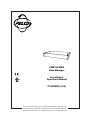
1
®
CM9760-DMR
Data Manager
Installation/
Operation Manual
C1520M-B (1/04)
Pelco • 3500 Pelco Way, Clovis • CA 93612-5699 USA • www.pelco.com
In North America and Canada: Tel (800) 289-9100 or FAX (800) 289-9150
International Customers: Tel +1 (559) 292-1981 or FAX +1 (559) 348-1120
CONTENTS
Section
Page
IMPORTANT SAFETY INSTRUCTIONS ............................................................................ 3
DESCRIPTION ................................................................................................................... 4
FRONT VIEW ............................................................................................................. 4
REAR VIEW ............................................................................................................... 4
LED ACTIVITY INDICATORS ............................................................................ 4
DIP SWITCHES ................................................................................................. 4
RJ-45 CONNECTORS ....................................................................................... 4
SCREW TERMINAL CONNECTORS ................................................................ 4
DB9 CONNECTOR ............................................................................................ 4
POWER JACK ................................................................................................... 4
INSTALLATION .................................................................................................................. 5
MOUNTING ................................................................................................................ 5
CONNECTIONS AND SWITCH SETTINGS .............................................................. 5
DATA MERGER MODE (P PROTOCOL) ........................................................... 5
SWITCH TABLES .............................................................................................. 7
DATA MERGER MODE (D PROTOCOL) .......................................................... 8
PORT EXPANDER MODE (CAMERAS) ........................................................... 10
PORT EXPANDER MODE (KEYBOARDS) ...................................................... 12
PROGRAMMING .............................................................................................................. 13
DATA MERGER ........................................................................................................ 13
PORT EXPANDER FOR CAMERAS ........................................................................ 17
PORT EXPANDER FOR KEYBOARDS .................................................................... 18
OPERATION .................................................................................................................. 21
TROUBLESHOOTING ...................................................................................................... 21
SPECIFICATIONS ............................................................................................................. 22
REGULATORY NOTICES ................................................................................................. 23
WARRANTY AND RETURN INFORMATION .................................................................... 24
LIST OF ILLUSTRATIONS
Figure
1
2
3
4
5
6
7
8
9
10
11
12
13
14
15
Page
Front View .......................................................................................................... 4
Rear View ........................................................................................................... 4
Rack-Mount Installation ..................................................................................... 5
Data Merger Mode (P Protocol) ......................................................................... 6
Data Merger Mode (D Protocol) ......................................................................... 9
Port Expander Mode (Cameras) ....................................................................... 11
Port Expander Mode (Keyboards) .................................................................... 12
System Window ................................................................................................ 13
Configuration Files Window .............................................................................. 14
Comms Screen ................................................................................................. 15
Cameras Screen ............................................................................................... 16
Comms Keyboard Expander Screen ................................................................ 18
Operators Screen .............................................................................................. 20
RJ-45 Cable Types ............................................................................................ 21
CM9760-DMR Dimension Diagram .................................................................. 22
LIST OF TABLES
Table
A
B
C
D
2
Page
Screw Terminal Connections .............................................................................. 7
SW1-SW5 Settings ............................................................................................ 7
SW6 Settings ..................................................................................................... 7
PTZ Port Addresses .......................................................................................... 17
Pelco Manual C1520M-B (1/04)
IMPORTANT SAFETY INSTRUCTIONS
1. Read these instructions.
2. Keep these instructions.
3. Heed all warnings.
4. Follow all instructions.
5. Do not use this apparatus near water.
6. Clean only with dry cloth.
7. Do not block any ventilation openings. Install in accordance with the manufacturer’s
instructions.
8. Do not install near any heat sources such as radiators, heat registers, stoves, or other
apparatus (including amplifiers) that produce heat.
9. Do not defeat the safety purpose of the polarized or grounding-type plug. A polarized
plug has two blades with one wider than the other. A grounding plug has two blades
and a third grounding prong. The wide blade or the third prong are provided for your
safety. If the provided plug does not fit into your outlet, consult an electrician for
replacement of the obsolete outlet.
10. Protect the power cord from being walked on or pinched particularly at plugs,
convenience receptacles, and the point where they exit from the apparatus.
11. Only use attachments/accessories specified by the manufacturer.
12. Use only with the cart, stand, tripod, bracket, or table specified by the manufacturer, or
sold with the apparatus. When a cart is used, use caution when moving the cart/
apparatus combination to avoid injury from tip-over.
13. Unplug this apparatus during lightning storms or when unused for long periods of time.
14. Refer all servicing to qualified service personnel. Servicing is required when the
apparatus has been damaged in any way, such as power-supply cord or plug is
damaged, liquid has been spilled or objects have fallen into the apparatus, the
apparatus has been exposed to rain or moisture, does not operate normally, or has
been dropped.
15. Apparatus shall not be exposed to dripping or splashing, and no objects filled with
liquids, such as vases, shall be placed on the apparatus.
16. WARNING: To reduce the risk of fire or electric shock, do not expose this apparatus to
rain or moisture.
17. CAUTION: These servicing instructions are for use by qualified service personnel
only. To reduce the risk of electric shock do not perform any servicing other than that
contained in the operating instructions unless you are qualified to do so.
Pelco Manual C1520M-B (1/04)
3
DESCRIPTION
The CM9760-DMR Data Manager is a five-port data distribution unit that can be programmed
to operate in three modes:
1.
2.
3.
Data Merger for CM9760-CC1 units (P protocol) and DX7100, DX7000, CM6800,
CM6700 units (D protocol)
Port Expander for pan/tilt/zoom (PTZ) cameras
Port Expander for CM9760 keyboards
FRONT VIEW
Figure 1 shows the front of the unit. The green power LED indicates the unit is on.
00977
Figure 1. Front View
REAR VIEW
Figure 2 shows the back of the unit.
DIP SWITCHES
LED ACTIVITY INDICATORS
DB9 CONNECTOR
2
1
PORT
3
4
5
ACTIVE
ACTIVE
ACTIVE
ACTIVE
ACTIVE
DATA
DATA
DATA
DATA
DATA
R R
+ -
T T
- +
R R
+ -
T T
- +
R R
+ -
T T
- +
R R
+ -
T T
- +
MODE
R R
+ -
T T
- +
9.0 VAC
POWER JACK
SCREW TERMINAL CONNECTORS
RJ-45 CONNECTORS
MODE SELECTION
DIP SWITCH
01133
Figure 2. Rear View
LED ACTIVITY INDICATORS
Each of the five ports has a green LED and a yellow LED. The green LEDs indicate the port
is selected. The yellow LEDs blink when there is port activity.
DIP SWITCHES
The back of the unit has six DIP switches. You can program the hardware of the five data
merger ports with the first five DIP switches. You can select the unit mode with the sixth switch.
RJ-45 CONNECTORS
You can use these five connectors to connect CM9760-CC1 units or CM9760 keyboards.
SCREW TERMINAL CONNECTORS
You can connect PTZ cameras, DX7100s, DX7000s, CM6800s, and CM6700s to these
connectors.
DB9 CONNECTOR
Reserved for future use.
POWER JACK
You can plug either a 120V AC adapter or 230V AC adapter into this jack. These adapters
drop the power jack’s input voltage to 9.0 VAC.
4
Pelco Manual C1520M-B (1/04)
INSTALLATION
The following items are supplied:
•
•
•
•
•
CM9760-DMR
AC adapter
1 10 ft (3 m) reversed cable
5 screw terminal adapters
4 screws and nylon washers for attaching to the rack mount
MOUNTING
NOTE: The unit is shipped
from the factory with the
rack ears attached.
Install the CM9760-DMR unit in a 19-inch (48.26 cm) rack. The unit occupies one rack unit
(1.75 inches or 4.45 cm) of space. You can mount the unit to something other than a
standard 19-inch rack by relocating the rack ears to another location.
00979
Figure 3. Rack-Mount Installation
NOTE: Countries
requiring CE compliance must use
shielded reversed
cables. Pelco recommends multiconductor, shielded,
24-gauge twisted
pairs such as Belden
9681.
CONNECTIONS AND SWITCH SETTINGS
DATA MERGER MODE (P PROTOCOL)
In the P protocol, the CM9760-DMR merges PTZ commands from CM9760-CC1 units
allowing you to control up to 32 PTZ cameras on one port. You can set the data manager to
operate with two, three, or four CC1 units. To operate the unit in P protocol, set switch 7 on
SW6 OFF.
Refer to Figure 4 for connections.
1.
Connect up to 32 PTZ cameras to Port 1. Refer to Table A for terminal connections.
2.
Connect CM9760-CC1 units to Ports 2-5 of the data manager. You must use RJ-45
reversed cables to make all connections.
3.
Set the DIP switches. Refer to Tables B and C. Figure 4 shows optimum switch settings.
4.
Pelco Manual C1520M-B (1/04)
a.
On SW6, set switch 1 ON if you have two CC1s connected to Ports 2 & 3.
b.
On SW6, set switch 2 ON if you have three or four CC1s connected to Ports 2-5.
c.
On SW6, set switch 8 ON if you want to give priority control to the CC1 on the
lower numbered port.
d.
On SW6, set the remaining switches OFF.
Connect the supplied AC adapter from the DMR unit and into a wall outlet.
5
DIP SWITCH 1 ON
MERGES PORTS 2 & 3 TO PORT 1
DIP SWITCH 2 ON
OPTIMUM SETTINGS
BAUD:
PARITY:
INTERFACE:
MERGES PORTS 2 - 5 TO PORT 1
OPTIMUM SETTINGS
BAUD:
PARITY:
INTERFACE:
9600
NONE
RS-422
DIP SWITCH 7 OFF
19200
NONE
RS-422
P PROTOCOL
DIP SWITCH 8 ON
GIVES PRIORITY CONTROL
TO THE LOWER NUMBERED
PORT. FOR EXAMPLE, PORT
2 HAS PRIORITY OVER PORT 3.
NOTE: IF DIP SWITCH 8 IS OFF, PRIORITY CONTROL IS
ON A FIRST COME FIRST SERVE BASIS.
CM9760-DMR
2
1
PORT
3
4
5
ACTIVE
ACTIVE
ACTIVE
ACTIVE
ACTIVE
DATA
DATA
DATA
DATA
DATA
R R
+ -
T T
- +
R R
+ -
T T
- +
R R
+ -
T T
- +
R R
+ -
T T
- +
MODE
R R
+ -
T T
- +
9.0 VAC
AC ADAPTER
RJ-45 REVERSED CABLES
DATA CABLE WIRED VIA
SCREW TERMINAL ADAPTERS
CM9760-CC1
CM9760-CC1
1-32
PR I N T ER
PR I N T ER
SPECTRA
COM 1
COM 1
THE CC1
BAUD RATES
MUST BE
19200.
COM 2
35
28
20
12
29
21
13
5
35
28
20
12
29
21
13
5
COM 2
¤
35
28
20
12
29
21
13
5
CM9760-CC1
THE PTZ CAMERA
BAUD RATES MUST
CM9760-CC1
BE 9600.
PR I N T ER
PR I N T ER
COM 1
COM 1
COM 2
COM 2
35
28
20
12
29
21
13
5
YOU MUST CONNECT AN RJ-45 REVERSED CABLE TO A PORT ON EACH CC1.
AS ILLUSTRATED, YOU CAN USE THE SAME PORT NUMBER ON EACH CC1.
2
1
PORT
ACTIVE
ACTIVE
DATA
DATA
R R
+ -
T T
- +
RR
+ -
CM9760-DMR
T T
- +
DAISY-CHAINING
GROUND
Tx+
Tx-
RS-422
R+
R+ R-
RR+
R-
1ST PTZ
32ND PTZ
2ND PTZ
20151
THE SCREW CONNECTOR ON PORT 1 SUPPORTS UP TO 32 CAMERAS.
REFER TO THE SWITCHER AND CAMERA INSTALLATION MANUALS
FOR VIDEO CONNECTION INSTRUCTIONS.
Figure 4. Data Merger Mode (P Protocol)
6
Pelco Manual C1520M-B (1/04)
Table A. Screw Terminal Connections
Terminal
RS-232 Function
RS-422 Function
RS-485 Function
1
2
3
4
5
Receive +
No Connection
Ground
No Connection
Transmit +
Receive +
Receive Ground
Transmit Transmit +
Receive +
Receive Ground
Transmit Transmit +
SWITCH TABLES
Table B. SW1-SW5 Settings
SW1-SW5 SETTINGS
BAUD
1
2
3
PARITY*
4
5
INTERFACE**
6
7
8
1200
2400
4800
9600
19200
57600
115200
off
on
off
off
on
off
on
off
off
on
off
on
on
on
off
off
off
on
off
on
on
none
none
odd
even
off
on
off
on
off
on
on
off
RS-422
RS-422
RS-232
RS-485
off
on
off
on
off
on
on
off
not used
not used
not used
not used
*Use either of the two DIP switch settings for no parity.
**Use either of the two DIP switch settings for RS-422 interface.
Table C. SW6 Settings
SW6 SETTINGS
FUNCTION
1
2
3
4
5
6
7
8**
Data Merger
Ports 2 & 3 to Port 1
Data Merger
Ports 2-5 to Port 1*
Port Expander Cameras
Port Expander Keyboards
on
off
off
off
off
off
off
off
on
off
off
off
off
off
off
off
off
on
off
off
on
off
off
off
off
off (P protocol)
on (D protocol)
off (P protocol)
on (D protocol)
off
off
off
off
off
*Use these DIP switch settings if you have three or four units connected to Ports 2-5.
**Set DIP switch 8 ON for priority control when in the Data Merger Mode.
Pelco Manual C1520M-B (1/04)
7
DATA MERGER MODE (D PROTOCOL)
You can also set the data manager to operate in D protocol allowing you to connect
D-protocol units—DX7100, DX7000, CM6800, and CM6700 units—and control PTZ
cameras connected to Port 1 of the data manager:
NOTE: Refer to the
DX7100, DX7000, CM6800,
or CM6700 Installation/
Operation manual as appropriate for programming
instructions.
•
For a CM6800 unit, a maximum of 32 PTZ cameras can be controlled through a single
DMR.
•
A DX7100/DX7000/CM6700 unit can address cameras 1-16 only; therefore, a
maximum of 16 PTZ cameras can be controlled through a single DMR. For control of
more than 16 PTZ cameras, a second DMR is required (contact Pelco Technical
Support at 1-800-289-9100 or 1-559-292-1981 for additional information).
To operate the data manager in D protocol, set switch 7 on SW6 ON.
Refer to Figure 5 for connections.
1.
Connect up to 32 PTZ cameras to Port 1. Refer to Table A for terminal connections.
2.
Connect D-protocol units (DX7100, DX7000, CM6800, CM6700) to Ports 2-5 of the
data manager. You must use RJ-45 reversed cables to make all connections.
3.
4.
8
Set the DIP switches. Refer to Tables B and C. Figure 5 shows optimum switch settings.
a.
On SW6, set switch 1 ON if you have two D-protocol units connected to Ports 2
and 3.
b.
On SW6, set switch 2 ON if you have three or four D-protocol units connected to
Ports 2-5.
c.
On SW6, set switch 8 ON if you want to give priority control to the D-protocol unit
on the lower numbered port.
d.
On SW6, set switches 3-6 OFF.
Connect the supplied AC adapter from the DMR unit and into a wall outlet.
Pelco Manual C1520M-B (1/04)
DIP SWITCH 1 ON
MERGES PORTS 2 & 3 TO PORT 1
OPTIMUM SETTINGS
OPTIMUM SETTINGS
BAUD:
PARITY:
INTERFACE:
BAUD:
PARITY:
INTERFACE:
2400
NONE
RS-422
DIP SWITCH 2 ON
MERGES PORTS 2 - 5 TO PORT 1
2400
NONE
RS-422
DIP SWITCH 7 ON
D PROTOCOL
DIP SWITCH 8 ON
GIVES CONTROL PRIORITY
TO THE LOWER NUMBERED
PORT. FOR EXAMPLE, PORT 2
HAS PRIORITY OVER PORT 3.
NOTE: IF DIP SWITCH 8 IS OFF, PRIORITY CONTROL IS
ON A FIRST-COME, FIRST-SERVED BASIS.
CM9760-DMR
2
1
PORT
3
4
5
ACTIVE
ACTIVE
ACTIVE
ACTIVE
ACTIVE
DATA
DATA
DATA
DATA
DATA
R R
+ -
T T
- +
R R
+ -
T T
- +
R R
+ -
T T
- +
R R
+ -
T T
- +
MODE
R R
+ -
T T
- +
9.0 VAC
AC ADAPTER
DATA CABLE WIRED VIA
SCREW TERMINAL ADAPTERS
CM6800
CM6800
ALARM
HZ
1
2
3
4
5
6
7
8
9
10
11
12
13
14
15
1 2 3 4 5 6 7 8
COM
16
75
1
5
2
6
CONTROL
ALARM
HZ
1
2
3
4
5
6
7
8
9
10
11
12
13
14
15
16
75
1 2 3 4 5 6 7 8
COM
1
5
2
6
17
18
19
20
21
22
23
24
25
26
27
28
29
30
31
32
41
42
43
44
1
2
3
4
46
47
48
5
CONTROL
1-32
17
18
19
20
21
22
23
24
25
26
27
28
29
30
31
32
41
42
43
44
1
2
3
4
33
34
35
36
37
38
39
40
45
46
47
48
5
6
7
8
7
4
8
A T T
+ -
R R T T
+ - + -
33
OUT
1
2
8
R R B
+ -
OUT
1
2
F
3
COM 1
34
35
36
37
38
39
40
45
ALTERNATE SOURCE INPUTS
6
7
8
120/230~
50/60 HZ
25 WATTS
VIDEO OUTPUTS
ALARM
1 2 3 4 5 6 7 8
THE DX7100, CM6800, AND CM6700
BAUD RATES MUST BE 2400.
SPECTRA
7
4
R R T T
+ - + -
F
3
120/230~
50/60 HZ
25 WATTS
VIDEO OUTPUTS
3
A T T
+ -
R R B
+ -
COM 1
ALTERNATE SOURCE INPUTS
THE PTZ CAMERA
BAUD RATES
MUST BE 2400.
3
PTZ
PTZ
CONTROL
PTZ
A T T
+ -
DX7100*
R R T T
+ - + -
OUT
1
2
COM 1
CM6700*
BACK OF DX7100
COM 1 PORT
PIN CONVERTER
T- –›R - (ON DMR)
• THE PTZ MUST BE SET TO ACCEPT ‘D’ PROTOCOL CONTROL.
FOR INFORMATION ON SETTING THE RECEIVER ADDRESS
FOR D-TYPE CONTROL, REFER TO THE DOCUMENTATION
SUPPLIED WITH THE PTZ EQUIPMENT.
RS-422 ADAPTER
T+ –›R + (ON DMR)
• YOU CAN LOOP VIDEO CABLES FROM A CM6800/CM6700 TO A DX7100/DX7000 OR USE A DISTRIBUTION
AMP SUCH AS THE CM9760-MDA. REFER TO THE SWITCHER AND CAMERA INSTALLATION MANUALS
FOR VIDEO CONNECTION INSTRUCTIONS.
*For the DX7100/DX7000/CM6700, a maximum of 16 PTZ cameras can be controlled through a single DMR. For control of more than 16 PTZ cameras,
a second DMR is required.
Figure 5. Data Merger Mode (D Protocol)
Pelco Manual C1520M-B (1/04)
9
PORT EXPANDER MODE (CAMERAS)
In this mode, a PTZ output from the CC1 can have up to 64 cameras on it. The CM9760-DMR
takes this high-speed, multi-control cable and breaks it down into groups of 16 at a slower
speed for direct use by the PTZ cameras.
Refer to Figure 6 for connections.
10
1.
Connect a CM9760-CC1 unit to Port 1. You must use an RJ-45 reversed cable.
2.
Connect PTZ cameras to Ports 2-5 of the data manager. Up to 16 cameras can be
connected to each port. Refer to Table A for terminal connections.
3.
Set the DIP switches. Refer to Tables B and C. Figure 6 shows optimum switch settings.
4.
Connect the supplied AC adapter from the DMR unit and into a wall outlet.
Pelco Manual C1520M-B (1/04)
OPTIMUM SETTINGS
BAUD:
PARITY:
INTERFACE:
OPTIMUM SETTINGS
BAUD:
PARITY:
INTERFACE:
19200
EVEN
RS-422
DIP SWITCH 3 ON
4800
NONE
RS-422
PORT EXPANDER
FOR PTZ CAMERAS
CM9760-DMR
2
1
PORT
3
4
5
ACTIVE
ACTIVE
ACTIVE
ACTIVE
ACTIVE
DATA
DATA
DATA
DATA
DATA
R R
+ -
T T
- +
R R
+ -
T T
- +
R R
+ -
T T
- +
R R
+ -
T T
- +
MODE
R R
+ -
T T
- +
9.0 VAC
DATA CABLES WIRED
VIA SCREW TERMINAL
ADAPTERS
AC ADAPTER
RJ-45 REVERSED
CABLE TO ANY
AVAILABLE PORT ON THE CC1
CM9760-CC1
1-16
PR I N T ER
COM 1
1-16
1-16
THE PTZ
CAMERA BAUD
RATES MUST
BE 4800.
1-16
COM 2
35
28
20
12
29
21
13
5
SPECTRA
¤
SPECTRA
¤
SPECTRA
¤
SPECTRA
¤
RJ-45 REVERSED CABLE TO VIDEO SWITCHER
THE CC1 BAUD RATES MUST BE 19200.
2
1
ACTIVE
ACTIVE
DATA
DATA
R R
+ -
T T
- +
RR
+ -
T T
- +
DAISY-CHAINING
GROUND
CM9760-DMR
Tx+
TxRS-422
R+
R+ R-
RR+
R-
1ST PTZ
16TH PTZ
2ND PTZ
PORTS 2 - 5 EACH SUPPORT UP TO 16 CAMERAS. REFER TO
THE SWITCHER AND CAMERA INSTALLATION MANUALS FOR
VIDEO CONNECTION INSTRUCTIONS.
20153
Figure 6. Port Expander Mode (Cameras)
Pelco Manual C1520M-B (1/04)
11
PORT EXPANDER MODE (KEYBOARDS)
NOTE: The DMR unit is
shipped from the factory in
this mode.
In this mode, four CM9760 keyboards can communicate with one CC1. This saves port
usage on the rear of the CM9760-CC1 because only one port is being used instead of four.
Refer to Figure 7 for connections.
1.
Connect a CM9760-CC1 unit to Port 1. You must use an RJ-45 reversed cable.
2.
Connect CM9760 keyboards to Ports 2-5 of the data manager. You must use RJ-45
reversed cables to make all connections.
3.
Set the DIP switches. Refer to Tables B and C. Figure 7 shows default switch settings.
4.
Connect the supplied AC adapter from the DMR unit and into a wall outlet.
DEFAULT SETTINGS
DEFAULT SETTINGS
DIP SWITCH 4 ON
BAUD:
PARITY:
INTERFACE:
BAUD:
PARITY:
INTERFACE:
PORT EXPANDER
FOR KEYBOARDS
19200
EVEN
RS-422
4800
EVEN
RS-422
CM9760-DMR
2
1
PORT
3
4
5
ACTIVE
ACTIVE
ACTIVE
ACTIVE
ACTIVE
DATA
DATA
DATA
DATA
DATA
R R
+ -
T T
- +
R R
+ -
T T
- +
R R
+ -
T T
- +
R R
+ -
T T
- +
MODE
R R
+ -
T T
- +
9.0 VAC
AC ADAPTER
RJ-45 REVERSED
CABLES
RJ-45 REVERSED
CABLE TO ANY
AVAILABLE PORT ON
THE CC1
CM9760-CC1
CM9505UPS
PRI NT ER
COM 1
COM 2
35
28
20
12
29
21
13
5
RJ-45 STRAIGHT
CABLES
THE CC1 BAUD RATE MUST BE 19200.
20154
THE KEYBOARD BAUD RATES MUST BE 4800.
Figure 7. Port Expander Mode (Keyboards)
12
Pelco Manual C1520M-B (1/04)
PROGRAMMING
You must define the ports and cameras in the CM9760-MGR System Manager before you
can use the CM9760-DMR. Refer to the CM9760-MGR Installation/User Manual (C547M-A)
for instructions on installing this software.
The following steps and screenshots are only examples of possible configurations for each
mode, except for the Data Merger Mode (D Protocol).
Additional configurations are possible.
DATA MERGER
1.
Open the system manager and log in.
Figure 8. System Window
Pelco Manual C1520M-B (1/04)
13
2.
Click the Sys Setup icon. The Configuration Files window opens.
3.
Enter a configuration name and node number and then click Add Node.
4.
Highlight the node and click Setup Files. The Setup System Configuration DMR
window opens.
Figure 9. Configuration Files Window
14
Pelco Manual C1520M-B (1/04)
5.
Click the Comms tab.
6.
Set the port number, equipment number, baud rate, and parity for each unit (up to four)
you connect to DMR Ports 2-5.
Figure 10 shows the system manager setup files for only one CC1.
a.
Port 6: The CM9760-DMR is connected to this port on one of the CC1 units.
b.
Equipment Number 9: The CM9760-DMR is always this number when operating
as a data merger for CC1 units.
c.
Baud: 9600.
d.
Parity: None.
The baud rate and parity for additional CC1s can be different and must be reflected in
the system manager setup files.
7.
Click Save.
Figure 10. Comms Screen
Pelco Manual C1520M-B (1/04)
15
NOTE: You can enter the
port number of any CC1.
They are all communicating
to the PTZ cameras via an
RS-422 communication
interface.
8. Click the Cameras tab. Cameras must be defined on each CC1 unit.
9. In the PTZ Port data fields enter the CC1 port number the CM9760-DMR is connected
to and the port address for the PTZ camera.
10. Click Save.
Figure 11. Cameras Screen
16
Pelco Manual C1520M-B (1/04)
PORT EXPANDER FOR CAMERAS
1. Open the system manager and log in.
2. Click the Sys Setup icon. The Configuration Files window opens. See Figure 9.
3. Enter a configuration name and node number and then click Add Node.
4. Highlight the node and click Setup Files. The Setup System Configuration DMR
window opens.
5. Click the Comms tab. See Figure 10.
6. Set the port number, equipment number, baud rate, and parity. The baud rate and
parity must be the same as the baud and parity of Switch 1 on the CM9760-DMR.
NOTE: You can only use
16 camera addresses for
each port. For example, the
address for cameras 17, 33,
and 49 is also 1. See
Table D.
a.
Port 7: The CM9760-DMR is connected to this port on the CC1 unit.
b.
Equipment Number 19: The CM9760-DMR is always this number when operating
as a port expander for cameras.
c.
Baud: 19200.
d.
Parity: Even.
7. Click Save.
8. Click the Cameras tab. See Figure 11.
9. In the PTZ Port data fields enter the CC1 port number the CM9760-DMR is connected
to and the port address for the PTZ camera.
10. Click Save.
Table D. PTZ Port Addresses
Camera
Address
DMR Port 2
Camera Number
DMR Port 3
Camera Number
DMR Port 4
Camera Number
DMR Port 5
Camera Number
1
2
3
4
5
6
7
8
9
10
11
12
13
14
15
16
1
2
3
4
5
6
7
8
9
10
11
12
13
14
15
16
17
18
19
20
21
22
23
24
25
26
27
28
29
30
31
32
33
34
35
36
37
38
39
40
41
42
43
44
45
46
47
48
49
50
51
52
53
54
55
56
57
58
59
60
61
62
63
64
Pelco Manual C1520M-B (1/04)
17
PORT EXPANDER FOR KEYBOARDS
1.
Open the system manager and log in.
2.
Click the Sys Setup icon. The Configuration Files window opens. See Figure 9.
3.
Enter a configuration name and node number and then click Add Node.
4.
Highlight the node and click Setup Files. The Setup System Configuration DMR
window opens.
5.
Click the Comms tab.
Figure 12. Comms Keyboard Expander Screen
18
Pelco Manual C1520M-B (1/04)
NOTE: The Keyboard
Expander fields appear
once you define the ports.
Refer to Figure 12.
Pelco Manual C1520M-B (1/04)
6.
Set the port number, equipment number, baud rate, and parity. The baud rate and parity
must be the same as the baud and parity of Switch 1 on the CM9760-DMR.
a.
Port 8: The CM9760-DMR is connected to this port on the CC1 unit.
b.
Equipment Number 23: The DMR is always this number when operating as a port
expander for keyboards.
c.
Baud: 19200.
d.
Parity: Even.
7.
Select the keyboard expander port number. Although the keyboards are connected to
Ports 2-5, you must reference them as Ports 1-4.
8.
Assign a keyboard number (KBD Num) to each keyboard expander port. Figure 12
shows that the first keyboard expander port is assigned number 5.
9.
Click Save.
19
10. Click the Operators tab.
11. Assign a PIN to the operator number. The operator number is the same as the
keyboard number (KBD Num). Figure 13 shows that the PIN for operator number 5 is
5555. You can edit the operator name and PIN in the Edit PIN fields.
12. Click Save.
Figure 13. Operators Screen
20
Pelco Manual C1520M-B (1/04)
OPERATION
The CM9760-DMR will function based on the mode you have selected.
After making all connections and settings, refer to the operation manual of each peripheral
component for detailed instructions on how to operate those devices.
TROUBLESHOOTING
Problem
Solution
Why is the yellow data LED not blinking
when I connect a keyboard?
Make sure all devices are connected
properly. Make sure you are using a
reversed cable. See Figure 14.
Why is the yellow data LED not blinking
when I send messages to a camera?
Check your system manager setup.
Why doesn’t the green active LED come
on?
Make sure the AC adapter is connected
from the unit and into a wall outlet. Check
your DIP switch settings.
Why is the yellow LED of the KBD port
blinking and the yellow LED of the CC1
port not blinking?
Make sure the CC1 is plugged into port 1;
it is reserved for this port. Check the DIP
switches for the proper baud and parity.
Why is the keyboard offline even though
the yellow LEDs on the KBD port and CC1
port are blinking?
Make sure the baud and parity settings to
the CC1 match those in the system
manager.
Why can’t I control the camera?
Check the camera wiring. Make sure the
DIP switch settings of the PTZ device
match those of the DMR. Check your
system manager setup.
What should I do if I can’t find a solution to
a problem?
Call Pelco’s 24-hour technical support at
1-800-289-9100 or 1-559-292-1981.
COMPARED "COLOR RUN"
IS IN OPPOSITE DIRECTION
COMPARED "COLOR RUN"
IS IN SAME DIRECTION
BROWN
BROWN
BROWN
STRAIGHT CABLE
BROWN
REVERSED CABLE
TO IDENTIFY A CABLE
TYPE, PHYSICALLY
ORIENT THE RJ-45
CABLE AS DEPICTED
IN THE ILLUSTRATIONS.
ORIENT THE CONNECTORS
SIDE BY SIDE. TAB
SIDE DOWN. USE
THE COLOR RUN
OF THE WIRES TO
DETERMINE CABLE
TYPE.
00989
Figure 14. RJ-45 Cable Types
Pelco Manual C1520M-B (1/04)
21
SPECIFICATIONS
ELECTRICAL
Input Voltage:
120V AC external adapter
230V AC external adapter
Power:
25 VA
Data Ports
Input/Output:
RJ-45 connectors, screw terminal connectors, DB9 connector
Indicators:
One green power LED
Five green port LEDs
Five yellow data LEDs
GENERAL
Dimensions:
See Figure 15.
Operating Temperature:
32° to 122°F (0° to 50°C)
Unit Weight:
5.20 lb (2.36 kg)
MECHANICAL
Connectors
Power:
Data Communication:
9.0 VAC jack
RJ-45, screw terminals, DB9
(Design and product specifications subject to change without notice.)
7.85
(19.93)
19.00 (48.26)
1.73
(4.39)
CM9760-DMR
Data Manager
Made In USA
9760
00990
17.40 (44.20)
NOTE: VALUES IN PARENTHESES ARE IN CENTIMETERS;
ALL OTHERS ARE IN INCHES.
Figure 15. CM9760-DMR Dimension Diagram
22
Pelco Manual C1520M-B (1/04)
REGULATORY NOTICES
This device complies with part 15 of the FCC Rules. Operation is subject to the following
two conditions: (1) this device may not cause harmful interference, and (2) this device must
accept any interference received, including interference that may cause undesired
operation.
RADIO AND TELEVISION INTERFERENCE
This equipment has been tested and found to comply with the limits of a Class B digital
device, pursuant to part 15 of the FCC rules. These limits are designed to provide
reasonable protection against harmful interference in a residential installation. This
equipment generates, uses, and can radiate radio frequency energy and, if not installed
and used in accordance with the instructions, may cause harmful interference to radio
communications. However there is no guarantee that the interference will not occur in a
particular installation. If this equipment does cause harmful interference to radio or
television reception, which can be determined by turning the equipment off and on, the user
is encouraged to try to correct the interference by one or more of the following measures:
•
Reorient or relocate the receiving antenna.
•
Increase the separation between the equipment and the receiver.
•
Connect the equipment into an outlet on a circuit different from that to which the
receiver is connected.
•
Consult the dealer or an experienced radio/TV technician for help.
You may also find helpful the following booklet, prepared by the FCC: “How to Identify and
Resolve Radio-TV Interference Problems.” This booklet is available from the U.S. Government Printing Office, Washington D.C. 20402.
Changes and Modifications not expressly approved by the manufacturer or registrant of this
equipment can void your authority to operate this equipment under Federal Communications Commission’s rules.
In order to maintain compliance with FCC regulations shielded cables must be used with
this equipment. Operation with non-approved equipment or unshielded cables is likely to
result in interference to radio and television reception.
Pelco Manual C1520M-B (1/04)
23
WARRANTY AND RETURN INFORMATION
WARRANTY
Pelco will repair or replace, without charge, any merchandise proved defective in
material or workmanship for a period of one year after the date of shipment. Exceptions to this warranty are as noted below:
•
•
•
•
•
•
•
•
•
•
Five years on Pelco manufactured cameras (CC3500/CC3600/CC3700 and
MC3500/MC3600 Series); two years on all other cameras.
Three years on Genex® Series (multiplexers, server, and keyboard) and 090
Series Camclosure® Camera System.
Two years on 100/150, 200 and 300 Series Camclosure® Camera Systems.
Two years on cameras and all standard motorized or fixed focal length lenses.
Two years on Legacy ® , CM6700/CM6800/CM6800E/CM8500/CM9500/
CM9740/CM9760 Matrix, DF5 and DF8 Series Fixed Dome products.
Two years on Spectra®, Esprit®, and PS20 Scanners, including when used in
continuous motion applications.
Two years on Esprit and WW5700 series window wiper (excluding wiper blades).
Eighteen months on DX Series digital video recorders.
One year (except video heads) on video cassette recorders (VCRs). Video
heads will be covered for a period of six months.
Six months on all pan and tilts, scanners or preset lenses used in continuous
motion applications (that is, preset scan, tour and auto scan modes).
Pelco will warrant all replacement parts and repairs for 90 days from the date of
Pelco shipment. All goods requiring warranty repair shall be sent freight prepaid to
Pelco, Clovis, California. Repairs made necessary by reason of misuse, alteration,
normal wear, or accident are not covered under this warranty.
Pelco assumes no risk and shall be subject to no liability for damages or loss
resulting from the specific use or application made of the Products. Pelco’s liability
for any claim, whether based on breach of contract, negligence, infringement of
any rights of any party or product liability, relating to the Products shall not exceed
the price paid by the Dealer to Pelco for such Products. In no event will Pelco be
liable for any special, incidental or consequential damages (including loss of use,
loss of profit and claims of third parties) however caused, whether by the negligence of Pelco or otherwise.
The above warranty provides the Dealer with specific legal rights. The Dealer may
also have additional rights, which are subject to variation from state to state.
If a warranty repair is required, the Dealer must contact Pelco at (800) 289-9100
or (559) 292-1981 to obtain a Repair Authorization number (RA), and provide the
following information:
1. Model and serial number
2. Date of shipment, P.O. number, Sales Order number, or Pelco invoice number
3. Details of the defect or problem
If there is a dispute regarding the warranty of a product which does not fall under
the warranty conditions stated above, please include a written explanation with
the product when returned.
Method of return shipment shall be the same or equal to the method by which the
item was received by Pelco.
RETURNS
In order to expedite parts returned to the factory for repair or credit, please call the
factory at (800) 289-9100 or (559) 292-1981 to obtain an authorization number
(CA number if returned for credit, and RA number if returned for repair).
All merchandise returned for credit may be subject to a 20% restocking and refurbishing charge.
Goods returned for repair or credit should be clearly identified with the assigned
CA or RA number and freight should be prepaid. Ship to the appropriate address
below.
If you are located within the continental U.S., Alaska, Hawaii or Puerto Rico:
Service Department
Pelco
3500 Pelco Way
Clovis, CA 93612-5699
If you are located outside the continental U.S., Alaska, Hawaii or Puerto Rico:
Intermediate Consignee
American Overseas Air Freight
320 Beach Road
Burlingame, CA 94010
USA
Ultimate Consignee
Pelco
3500 Pelco Way
Clovis, CA 93612-5699
USA
REVISION HISTORY
Manual #
C1520M
C1520M-A
C1520M-B
Date
9/01
4/02
1/04
Comments
Original version.
Added Data Merger Mode (D Protocol) section. Added Figure 5.
Revised Figure 5 and associated text. Added references to DX7100 where applicable. Updated Regulatory Notices.
® Pelco, the Pelco logo, Spectra, Genex, Legacy, Esprit, and Camclosure are registered trademarks of Pelco.
24
© Copyright 2004, Pelco.
All rights reserved.
Pelco Manual C1520M-B (1/04)