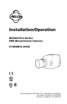
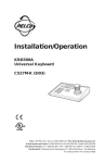
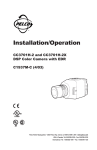
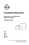
1
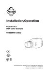
INSTALLATION/OPERATION
®
090 Series Camclosure®
Indoor Integrated Camera
System
C2462M-A (6/03)
CONTENTS
Section
Page
IMPORTANT SAFEGUARDS AND WARNINGS .................................................................................... 3
WELCOME ......................................................................................................................................... 4
REMOVE THE BUBBLE ....................................................................................................................... 5
INSTALL THE BACK BOX ................................................................................................................... 6
INSTALLATION TO SURFACE OF A CEILING/WALL .................................................................. 7
IN-CEILING INSTALLATION – SUSPENDED CEILING ............................................................... 8
IN-CEILING INSTALLATION – FIXED CEILING/WALL ............................................................... 9
INSTALLATION TO SURFACE OF A 4S STANDARD ELECTRICAL BOX ..................................... 10
INSTALLATION IN A 4S DEEP ELECTRICAL BOX ...................................................................... 11
CAMERA POSITIONING ..................................................................................................................... 12
CAMERA ADJUSTMENTS .................................................................................................................. 13
VARIFOCAL LENS ZOOM AND FOCUS ADJUSTMENTS .......................................................... 13
VARIFOCAL LENS AUTO IRIS LEVEL ADJUSTMENT ................................................................ 13
SWITCH SETTINGS .................................................................................................................. 14
SWITCH SETTINGS FOR FIXED FOCAL LENGTH LENS WITHOUT AUTO IRIS ................ 14
SWITCH SETTINGS FOR VARIFOCAL LENS .................................................................... 14
VERTICAL PHASE ADJUSTMENT (24 VAC OPERATION ONLY) ................................................ 15
HOW TO ADJUST THE PHASE CONTROL ....................................................................... 15
REINSTALL THE DOME ...................................................................................................................... 16
DOME LINER INSTALLATION ................................................................................................... 16
BUBBLE INSTALLATION ............................................................................................................ 16
SERVICE CONNECTOR ...................................................................................................................... 17
SPECIFICATIONS ............................................................................................................................... 18
WARRANTY AND RETURN INFORMATION ......................................................................................... 19
LIST OF ILLUSTRATIONS
Figure
1
2
3
4
5
6
7
8
9
10
11
12
13
14
15
2
Page
How to Remove the Bubble ................................................................................................. 5
Ceiling/Wall Installation ...................................................................................................... 7
Concrete Ceiling/Wall Installation ...................................................................................... 7
Ceiling Tile Installation ........................................................................................................ 8
How to Remove Surface Mount Ring From Back Box ......................................................... 8
In-ceiling Installation to a Fixed Ceiling/Wall ..................................................................... 9
4S Standard Electrical Box Installation ............................................................................... 10
4S Deep Electrical Box Installation ..................................................................................... 11
How to Position Camera ...................................................................................................... 12
Location of Zoom and Focus Adjustments ........................................................................... 13
Varifocal Lens Adjustments ................................................................................................. 13
Vertical Phase Adjustment ................................................................................................... 15
How to Install the Dome Liner ............................................................................................. 16
How to Install the Bubble .................................................................................................... 16
How to Connect the 2.5 mm Monaural Headphone Plug to the Coaxial Cable .................. 17
C2462M-A (6/03)
IMPORTANT SAFEGUARDS AND WARNINGS
1. Installation and servicing should be done only by qualified service personnel and conform to all
local codes.
2. Unless the unit is specifically marked as a NEMA Type 3, 3R, 3S, 4, 4X, 6, or 6P enclosure, it is
designed for indoor use only and must not be installed where exposed to rain and moisture.
3. Use only installation methods and materials capable of supporting four times the maximum
specified load.
REGULATORY NOTICES
This equipment has been tested and found to comply with the limits of a Class B digital device,
pursuant to part 15 of the FCC rules. These limits are designed to provide reasonable protection
against harmful interference in a residential installation. This equipment generates, uses, and can
radiate radio frequency energy and, if not installed and used in accordance with the instructions,
may cause harmful interference to radio communications. However there is no guarantee that the
interference will not occur in a particular installation. If this equipment does cause harmful
interference to radio or television reception, which can be determined by turning the equipment off
and on, the user is encouraged to try to correct the interference by one or more of the following
measures:
• Reorient or relocate the receiving antenna.
• Increase the separation between the equipment and the receiver.
• Connect the equipment into an outlet on a circuit different from that to which the receiver is
connected.
• Consult the dealer or an experienced radio/TV technician for help.
Changes and Modifications not expressly approved by the manufacturer or registrant of this
equipment can void your authority to operate this equipment under Federal Communications
Commissions rules.
C2462M-A (6/03)
3
WELCOME
Thank you for purchasing Pelco’s Camclosure® Integrated Camera System for indoor applications.
The ICS090 Series system integrates a camera and lens package in a small, discreet dome. The
system is easy to install and can be mounted to the surface of a ceiling/wall or recessed in a
ceiling/wall.
Prior to installation of your new system, thoroughly familiarize yourself with the information in this
manual.
The following is supplied with the 090 Series Camclosure Integrated Camera System:
Qty.
1
1
2
2
2
2
4
Description
Assembled ICS090 Series Camclosure (back box, bubble, and camera module)
Adapter plate
8-32 x 1.00-inch Phillips pan head screws
8-32 x .750-inch self-tapping screws
8-32 x 2.50-inch self-tapping screws
10-32 x 1.50-inch self-tapping screws
C2462M-A (6/03)
REMOVE THE BUBBLE
Turn the bubble counterclockwise and lift (refer to Figure 1). Place the bubble on a non-abrasive
surface.
If the unit is supplied with a liner, remove the liner before installing the unit. To remove the liner,
gently lift it from the unit. Place the liner to the side; it will be reinstalled along with the bubble
after the installation has been completed.
Figure 1. How to Remove the Bubble
C2462M-A (6/03)
5
INSTALL THE BACK BOX
The installation methods for the ICS090 Series include the following:
•
•
•
•
•
Mount to the surface of a ceiling/wall
Install in a suspended ceiling
Install in a fixed ceiling/wall
Mount to the surface of a 4S standard electrical box
Install in a 4S deep electrical box
Select the best method for your installation and refer to the following pages for instructions.
6
C2462M-A (6/03)
Installation to Surface of a Ceiling/Wall
Refer to Figure 2 for the following steps. Refer to Figure 3 if installing the unit to a concrete
ceiling/wall.
1. Pull video and power wires through the ceiling/wall.
2. Connect the video cable/wires.
BNC – Connect the BNC connector from the Camclosure to a mating BNC connector.
Twisted Pair – Blue wire = Video +
Gray wire = Video 3. Connect the power wires.
Voltage Red Wire Black Wire
12 VDC
+
Ground
24 VAC
~
~
AC Operation Only – If you are wiring more than one ICS090 Camclosure to the same
transformer, connect one side of the transformer to the red wire on all units, and connect the
other side of the transformer to the black wire on all units. Failure to connect all of the units
the same way will cause the cameras to be out of phase with each other and may produce a
vertical roll when switching between cameras.
4. Use 6-32 toggle bolts and
attach the surface mount
ring and back box to the
mounting surface. For a
concrete ceiling/wall
installation use 8-32
mounting hardware.
Figure 2. Ceiling/Wall Installation
Figure 3. Concrete Ceiling/Wall Installation
C2462M-A (6/03)
7
In-Ceiling Installation – Suspended Ceiling
Refer to Figure 4 for the following steps.
1. Remove the ceiling tile from the ceiling.
2. Cut a four-inch diameter hole in the ceiling tile.
3. Remove the surface mount ring from the back box. Refer to Figure 5 and do the following:
a. Place fingers on the circular marks located on the sides of the surface mount ring.
b. Pinch the sides.
c. Lift and remove the surface mount ring from the back box. Do not discard surface mount
ring, because it is required to complete the installation.
4. Turn the surface mount ring upside down and place it on the inside of the ceiling tile.
5. Attach the back box to the ceiling tile
and surface mount ring with the two
10-32 x 1.50-inch self-tapping screws
(supplied).
SURFACE MOUNT RING
CEILING
TILE
6. Replace the ceiling tile.
7. Remove an adjacent ceiling tile
and connect the video cable/wires.
BNC – Connect the BNC connector
from the Camclosure to a mating
BNC connector.
Twisted Pair – Blue wire = Video +
Gray wire = Video -
BACK BOX
10-32 x 1.50
SELF-TAPPING
SCREWS
(SUPPLIED)
Figure 4. Ceiling Tile Installation
8. Connect the power wires.
Voltage Red Wire Black Wire
12 VDC
+
Ground
24 VAC
~
~
AC Operation Only – If you are
wiring more than one ICS090
Camclosure to the same transformer,
connect one side of the transformer
to the red wire on all units, and
connect the other side of the
transformer to the black wire on all
units. Failure to connect all of the
units the same way will cause the
cameras to be out of phase with
each other and may produce a
vertical roll when switching between
cameras.
8
STANDOFF
BACK BOX
SURFACE
MOUNT RING
Figure 5. How to Remove Surface Mount Ring
from Back Box
C2462M-A (6/03)
In-Ceiling Installation – Fixed Ceiling/Wall
Refer to Figure 6 for the following steps.
1. Cut a four-inch diameter hole in the ceiling/wall.
2. Remove the surface mount ring from the back box. Refer to Figure 5 and do the following:
a. Place fingers on the circular marks located on the sides of the surface mount ring.
b. Pinch the sides.
c. Lift and remove the surface mount ring from the back box.
3. Connect the video cable/wires.
BNC – Connect the BNC connector from the Camclosure to a mating BNC connector.
Twisted Pair – Blue wire = Video +
Gray wire = Video 4. Connect the power wires.
Voltage Red Wire Black Wire
12 VDC
+
Ground
24 VAC
~
~
AC Operation Only – If you are wiring more than one ICS090 Camclosure to the same
transformer, connect one side of the transformer to the red wire on all units, and connect the
other side of the transformer to the black wire on all units. Failure to connect all of the units
the same way will cause the cameras to be out of phase with each other and may produce a
vertical roll when switching between cameras.
5. Use 3-16 toggle bolts and attach the back box to the mounting surface.
Figure 6. In-Ceiling Installation to a Fixed Ceiling/Wall
C2462M-A (6/03)
9
Installation to Surface of a 4S Standard Electrical Box
Refer to Figure 7 for the following steps.
1. Attach the adapter ring to the 4S box with the two 8-32 x 1.00-inch screws (supplied).
2. Connect the video cable/wires.
BNC – Connect the BNC connector from the Camclosure to a mating BNC connector.
Twisted Pair – Blue wire = Video +
Gray wire = Video 3. Connect the power wires.
Voltage Red Wire Black Wire
12 VDC
+
Ground
24 VAC
~
~
AC Operation Only – If you are wiring more than one ICS090 Camclosure to the same
transformer, connect one side of the transformer to the red wire on all units, and connect the
other side of the transformer to the black wire on all units. Failure to connect all of the units
the same way will cause the cameras to be out of phase with each other and may produce a
vertical roll when switching between cameras.
4. Attach the surface trim ring and back box to the adapter plate with the two 8-32 x 2.50-inch
screws (supplied).
4S STANDARD
ELECTRICAL BOX
CEILING/
WALL
8-32 X 1.00
(SUPPLIED)
8-32 X 2.50
(SUPPLIED)
OPTIONAL
ADAPTER RING
BACK BOX AND
SURFACE MOUNT
RING
Figure 7. 4S Standard Electrical Box Installation
10
C2462M-A (6/03)
Installation in a 4S Deep Electrical Box
Refer to Figure 8 for the following steps.
1. Remove the surface mount ring from the back box. Refer to Figure 5 and do the following:
a. Place fingers on the circular marks located on the sides of the surface mount ring.
b. Pinch the sides.
c. Lift and remove the surface mount ring from the back box.
2. Attach the adapter ring to the 4S box with the two 8-32 x 1.00-inch screws (supplied).
3. Connect the video cable/wires.
BNC – Connect the BNC connector from the Camclosure to a mating BNC connector.
Twisted Pair – Blue wire = Video +
Gray wire = Video 4. Connect the power wires.
Voltage Red Wire Black Wire
12 VDC
+
Ground
24 VAC
~
~
AC Operation Only – If you are wiring more than one ICS090 Camclosure to the same
transformer, connect one side of the transformer to the red wire on all units, and connect the
other side of the transformer to the black wire on all units. Failure to connect all of the units
the same way will cause the cameras to be out of phase with each other and may produce a
vertical roll when switching between cameras.
5. Attach the back box to the adapter plate with the two 8-32 x .750-inch screws (supplied).
4S DEEP ELECTRICAL BOX
CEILING/
WALL
ADAPTER
RING
8-32 x 1.00
(SUPPLIED)
8-32 X .750
(SUPPLIED)
BACK
BOX
Figure 8. 4S Deep Electrical Box Installation
C2462M-A (6/03)
11
CAMERA POSITIONING
Manually rotate and tilt the camera module to position the camera. Do not over-rotate the module.
Excessively turning the module in one direction could result in damage to the wiring.
�
�
�
� Tilt 140°
� Pan 360° � Rotation 360°
Figure 9. How to Position Camera
12
C2462M-A (6/03)
CAMERA ADJUSTMENTS
VARIFOCAL LENS ZOOM AND FOCUS ADJUSTMENTS
1. Select a field of view by turning
the zoom adjustment ring
clockwise/counterclockwise.
Refer to Figure 10.
2. Tighten the zoom locking
screw.
3. Adjust the focus by moving
the focus locking screw
clockwise/counterclockwise.
4. Tighten the focus locking
screw.
Figure 10. Location of Zoom and Focus Adjustments
VARIFOCAL LENS AUTO IRIS LEVEL ADJUSTMENT
To adjust the auto iris level do the
following:
1. Manually rotate the camera
module to access the auto iris
level adjustment (refer to
Figure 11).
2. Turn the screw clockwise to
decrease the brightness level and
counterclockwise to increase the
brightness level.
Figure 11. Varifocal Lens Adjustments
C2462M-A (6/03)
13
SWITCH SETTINGS
Switch Settings for Fixed Focal Length Lens Without Auto Iris
Refer to the switch drawing. The switch is located next to the lens. Automatic backlight compensation (factory setting) is used under varying lighting conditions (such as outdoors) or fixed lighting
conditions where there are no bright spots that darken other picture details. Manual backlight
compensation is used in fixed lighting conditions to optimize the picture detail when there are
bright spots.
ABL
OFF
Manual backlight compensation: BLC switch ON
ABL switch OFF
OFF
NOT USED
ON
BL
BLC switch OFF
ABL switch ON
Y
Auto backlight compensation:
DC
Not used
OFF
Y/DC switch:
ALC
Always ELC
ELC
FACTORY SETTINGS
ALC/ELC switch:
= SWITCH POSITION
The high resolution camera
with varifocal lens and auto
iris is configured at the factory
for optimal performance in
lighting conditions where auto
iris is required. It is also
configured with the shutter
speed set at 1/60 (NTSC) or
1/50 (PAL) and AGC set at 6 dB
of gain.
AE Functions
Switch Settings for Varifocal Lens
1
2
3
4
5
6
7
8
AWB Automatic white balance
FACTORY SETTINGS
GAM Gamma function
1 2 3 4 5 6 7 8
AGC Automatic gain control
ESC Electronic shutter control
BLC Backlight compensation
FL
Flickerless
OFF
AE Automatic exposure
= SWITCH POSITION
Not used
To enable automatic exposure
Turn on switch 7, and then turn on/off switch 4
for electronic shutter control, switch 5 for
backlight compensation, and switch 6 for
flickerless motion.
To enable auto iris and manually set
shutter speed
Turn off switch 7; set switches 4, 5, and 6 for
the desired shutter speed.
CAUTION: Do not change the shutter speed
To manually set and lock AWB
Place a white background in front of camera
and turn off switch 1.
For gamma correction
Set switch 2 to accurately reproduce scene
brightness; when turned on, y = 0.6, and when
turned off, y = 1.0.
For gain control
Switch 3 On increases gain by 6 dB, and
switch 3 Off increases gain by 18 dB.
14
unless you understand how changing the
settings will affect the scene detail.
Shutter
Speed
1/60 (NTSC)
1/50 (PAL)
1/100
1/250
1/500
1/1000
1/2000
1/4000
1/10000
7
Off
Switch Number and Position
6
5
4
On
On
On
Off
On
Off
On
Off
On
Off
On
Off
Off
On
On
Off
Off
On
On
On
Off
Off
Off
Off
C2462M-A (6/03)
VERTICAL PHASE ADJUSTMENT (24 VAC OPERATION ONLY)
When using more than one camera power supply, a brief vertical roll may occur on the monitor
when a camera view is switched. To eliminate vertical roll reverse the 24 VAC connections on one
camera. If both cameras are connected to the same transformer, this should solve the problem. If
reversing the connections does not solve the problem, adjust the phase control by synchronizing, or
line-locking, the cameras to one another.
How to Adjust the Phase Control
It may be necessary to have two people in communication when synchronizing the cameras: one
person at the camera and another person at the monitor to observe the vertical roll and the effect
of any adjustments made at the camera.
To synchronize the cameras:
1. Choose a reference camera to which all other cameras will be phased.
2. Select a camera and synchronize it to the reference camera by turning the phase adjustment
control (refer to Figure 12) clockwise and/or counterclockwise.
3. Each time an adjustment is made, switch back and forth
between the camera you are adjusting and the reference
camera. Repeat this process as many
times as necessary, until the roll between
the cameras is no longer noticeable.
4. Adjust the phase of all other cameras by
repeating steps 2 through 3. Always adjust
to the reference camera selected in step 1.
NOTE: The preferred method for camera
phase adjustment is to use a dual trace
oscilloscope to align the vertical sync
pulses of the reference camera to the
selected camera(s).
C2462M-A (6/03)
Figure 12. Vertical Phase Adjustment
15
REINSTALL THE DOME
DOME LINER INSTALLATION
If the unit is supplied with a dome liner, reinstall the liner before installing the bubble. To install the
liner refer to Figure 13 and do the following:
1. Align the studs located on the camera module with the clips on the liner.
2. Lightly pinch the sides of the liner, opposite from the clips, and place clips over the studs.
3. Once the liner is secure, position the viewing window of the liner over the lens of the camera.
4. Install the bubble.
Figure 13. How to Install the Dome Liner
BUBBLE INSTALLATION
To install the bubble refer to
Figure 14 and do the following:
1. Align the standoffs of the
bubble with the slots of the
back box.
2. Turn the bubble clockwise,
until it locks in place.
Figure 14. How to Install the Bubble
16
C2462M-A (6/03)
SERVICE CONNECTOR
An optional 4-foot service/monitor cable, part number ICS090-SC, is available for on-site setup and
adjustments. To use the cable simply plug one end of the cable directly into the service connector
of the ICS090 and connect the other end to any standard BNC (VIDEO IN) connector on a monitor.
To assemble a longer service cable for the ICS090 Series Camclosure, purchase the following parts
at a local electronics supply store:
1
1
1
2.5 mm monaural headphone plug
CPM 88 miniature coaxial connector
RG174/U coaxial cable
To assemble the cable:
1. Attach the CPM 88 miniature coaxial connector to one end of the cable. Follow the directions
supplied with the miniature coaxial connector.
2. Refer to Figure 15 and do the following to attach the 2.5 mm monaural plug to the other end of
the coaxial cable:
a. Remove the support sleeve from the plug, and then slip the support sleeve over the end of
the cable.
b. Prepare the cable.
c. Solder the center connector of the cable to the center pin of the plug.
d. Thread the braid of the cable through the hole in the crimp pin, and then solder the braid to
the top of the crimp pin.
e. Crimp the end of the crimp pin around the cable.
f. Reassemble the support sleeve and the plug.
CENTER CONDUCTOR
COAXIAL
CABLE
BRAID (SHIELD)
2.5 mm MONAURAL
HEADPHONE PLUG
Figure 15. How to Connect the 2.5 mm Monaural Headphone Plug to the Coaxial Cable
C2462M-A (6/03)
17
SPECIFICATIONS
BACKBOX
Electrical
Input Voltage:
Power Consumption:
Video Connector:
General
Pan/Tilt Adjustment
Pan:
Tilt:
Rotation:
Construction
Back Box and
Surface Mount Ring:
Bubble:
Finish:
Environment:
Operating Temperature:
Weight
Unit:
Shipping:
12 VDC or 24 VAC (±10%), auto-sensing
3 watts or less
BNC
360°
140° (20° to 160° range)
360°
ABS plastic
Polycarbonate
White or black
Indoor
32°F to 120°F (0° to 49°C)
.52 lb (.24 kg)
2 lb (.91 kg)
(Design and product specifications subject to change without notice.)
NOTE: VALUES IN PARENTHESES ARE CENTIMETERS; ALL OTHERS ARE INCHES.
18
C2462M-A (6/03)
WARRANTY AND RETURN INFORMATION
WARRANTY
Pelco will repair or replace, without charge, any merchandise proved defective in material or workmanship for a period of one year after the date of
shipment. Exceptions to this warranty are as noted below:
•
•
•
•
•
•
•
•
•
•
Five years on Pelco manufactured cameras (CC3500/CC3600/CC3700 and MC3500/MC3600 Series); two years on all other cameras.
Three years on Genex® Series (multiplexers, server, and keyboard) and 090 Series Camclosure® Camera System.
Two years on 100/150, 200 and 300 Series Camclosure® Camera Systems.
Two years on cameras and all standard motorized or fixed focal length lenses.
Two years on Legacy®, CM6700/CM6800/CM6800E/CM8500/CM9500/CM9740/CM9760 Matrix, DF5 and DF8 Series Fixed Dome products.
Two years on Spectra®, Esprit®, and PS20 Scanners, including when used in continuous motion applications.
Two years on Esprit and WW5700 series window wiper (excluding wiper blades).
Eighteen months on DX Series digital video recorders.
One year (except video heads) on video cassette recorders (VCRs). Video heads will be covered for a period of six months.
Six months on all pan and tilts, scanners or preset lenses used in continuous motion applications (that is, preset scan, tour and auto scan modes).
Pelco will warrant all replacement parts and repairs for 90 days from the date of Pelco shipment. All goods requiring warranty repair shall be sent
freight prepaid to Pelco, Clovis, California. Repairs made necessary by reason of misuse, alteration, normal wear, or accident are not covered under
this warranty.
Pelco assumes no risk and shall be subject to no liability for damages or loss resulting from the specific use or application made of the Products.
Pelco’s liability for any claim, whether based on breach of contract, negligence, infringement of any rights of any party or product liability, relating to
the Products shall not exceed the price paid by the Dealer to Pelco for such Products. In no event will Pelco be liable for any special, incidental or
consequential damages (including loss of use, loss of profit and claims of third parties) however caused, whether by the negligence of Pelco or
otherwise.
The above warranty provides the Dealer with specific legal rights. The Dealer may also have additional rights, which are subject to variation from
state to state.
If a warranty repair is required, the Dealer must contact Pelco at (800) 289-9100 or (559) 292-1981 to obtain a Repair Authorization number (RA), and
provide the following information:
1. Model and serial number
2. Date of shipment, P.O. number, Sales Order number, or Pelco invoice number
3. Details of the defect or problem
If there is a dispute regarding the warranty of a product which does not fall under the warranty conditions stated above, please include a written
explanation with the product when returned.
Method of return shipment shall be the same or equal to the method by which the item was received by Pelco.
RETURNS
In order to expedite parts returned to the factory for repair or credit, please call the factory at (800) 289-9100 or (559) 292-1981 to obtain an
authorization number (CA number if returned for credit, and RA number if returned for repair).
All merchandise returned for credit may be subject to a 20% restocking and refurbishing charge.
Goods returned for repair or credit should be clearly identified with the assigned CA or RA number and freight should be prepaid. Ship to the
appropriate address below.
If you are located within the continental U.S., Alaska, Hawaii or
Puerto Rico:
Service Department
Pelco
3500 Pelco Way
Clovis, CA 93612-5699
If you are located outside the continental U.S., Alaska, Hawaii or Puerto Rico:
Intermediate Consignee
Ultimate Consignee
American Overseas Air Freight
Pelco
320 Beach Road
3500 Pelco Way
Burlingame, CA 94010
Clovis, CA 93612-5699
USA
USA
® Pelco, the Pelco logo, Spectra, Genex, Legacy, Esprit, and Camclosure are registered trademarks of Pelco.
© Copyright 2003, Pelco. All rights reserved.
REVISION HISTORY
Manual #
C2462M
C2462M-A
Date
11/02
1/03
C2462M-A (6/03)
Comments
Original version.
Added Regulatory Notices for FCC Class B.
19
®
World Headquarters
3500 Pelco Way
Clovis, California 93612 USA
USA & Canada
Tel: 800/289-9100
Fax: 800/289-9150
International
Tel: 1-559/292-1981
Fax: 1-559/348-1120
www.pelco.com
ISO9001
Orangeburg, New York Las Vegas, Nevada Eindhoven, The Netherlands Wokingham, United Kingdom Montreal, Canada