1
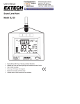
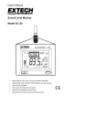
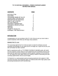
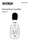
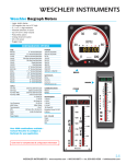
User Manual
Sound Level Alert
Model SL130
Introduction
Thank you for selecting the Extech SL130 Sound Level Alert. Designed for wall mount, tripod
mount, desktop, or hand held operation this meter meets ANSI and IEC Type 2 Sound Level Meter
standards.
The SL130 offers a High/Low Alarm Limit feature where four two-color high intensity LEDs and a
large OVER indicator provide alarm alerts when limits are exceeded. The SL130’s physical Alarm
Output circuit can be used to drive the optional Alarm Module Kit to power a larger, remote
indicating device such as a “QUIET” sign.
Professional features include programmable A/C Weighting, Fast/Slow Response time, Max
Memory with time stamp, and a Clock display. The microphone can be rotated 180 degrees to
accommodate any meter location or it can be placed at a remote location using the optional Remote
Microphone Cable. A programmable ON/OFF time extends battery life to 30 days when
programmed 8 hours per day. The bright LED’s are functional only when the AC power adaptor is
used.
This device is shipped fully tested and calibrated and, with proper use, will provide years of reliable
service. Please visit the Extech Instruments website (www.extech.com) to check for the latest
version of this User Guide. Extech Instruments is an ISO-9001 certified company.
2
SL130-EU-EN v3.6 08/13
Meter Description
1.
Microphone
2.
Over Limit Display
3.
Bargraph
4.
dB display
5.
OFF/ON/AUTO switch
6.
Alert LEDs
7.
Clock display
8.
Max level display with time stamp
9.
Set limit
10. MAX RESET button
Rear Control Panel
1.
Range select switch
2.
Time set buttons
3.
Limit set buttons
4.
Calibration adjustment
5.
A/C select button
6.
F/S select button
1
30-80
2
4 5 6
3
80-130
LIMIT
60-110
Side Panel
1.
Alert switch – Green position
2.
Alert switch – Red-Green position
3.
Alert switch – Red position
4.
High-Low Alarm switch
5.
Remote Alarm output connector
6.
AC adaptor connector
Rear Panel
1.
Tilt stand
2.
Battery compartment
3.
AC Adaptor connector
4.
Remote Alarm output connector
5.
Windscreen
3
SL130-EU-EN v3.6 08/13
Sound Level Monitor Operation
Measurement Considerations
1. Use a windscreen to cover the microphone in windy conditions.
2. Calibrate the meter often, especially if the meter has been idle for a long period of time.
3. Do not store/operate the meter in areas of high temperature or humidity.
4. Keep the meter and the microphone dry.
5. Avoid severe vibration when using the meter.
6. Remove the battery when the meter will be stored for long periods of time.
Initial Configuration
1. Connect the AC adaptor to the side or rear AC adaptor connector
OR Install 8 AA batteries
2. Setting the TIME
a)
Press and Hold the Time SET button until the hours display begins to flash.
b)
Press the Time up arrow button until the hour is set.
c)
Press the SET button. The minutes display will flash. Adjust as needed.
d)
Press the SET button to step through and the arrow button to adjust;
Time of day
Hour
Time of day
Minutes
Time of day
AM / PM / 24 Hour
Year
Month
Day
Auto ON Hour
Auto ON Minutes
Auto OFF Hour
Auto OFF Minute
A/C Frequency Weighting
Change the Frequency Weighting by pressing the 'A/C' button. The 'A' or 'C' icon will appear on the
display.
With ‘A’ weighting selected, the frequency response of the meter is similar to the response of the
human ear. ‘A’ weighting is commonly used for environmental or hearing conservation programs
such as OSHA regulatory testing and noise ordinance law enforcement. ‘C’ weighting is a much
flatter response and is suitable for the sound level analysis of machines, engines, etc.
Most noise measurements are performed using 'A' Weighting and SLOW Response.
Slow/ Fast Response
Press the ‘F/S’ button to select Fast or Slow response as desired. F or S will appear in the bottom
of the LCD display.
Select FAST to capture noise peaks and noises that occur very quickly. Select the SLOW response
to monitor a sound source that has a consistent noise level or to average quickly changing levels.
Select SLOW response for most applications.
4
SL130-EU-EN v3.6 08/13
Range Selection
Slide the Range switch to the 30-80, 60-110 or the 80-130 position. The selected
range will be indicated on the LCD bar graph. If the measured dB level exceeds
the range selected “OL” will be displayed. If the measured dB level is below the
selected range “- - -“ will be displayed.
Normally, select the range in which the upper dB level is greater than any expected sound
pressure level. The 60 to 110dB range is the most commonly used range. Use the 30 to
80dB range in quieter areas such as offices and classrooms.
Note: When the range is changed the Max display may indicate an overload “OL”. Press
the MAX RESET button to clear the MAX display.
High Limit Set
Press the up or down LIMIT arrow buttons to set the High/Low limit set=point
as displayed on the LCD. If the measured dB level exceeds the set limit, the
OVER indication will appear in the display and the over limit signal will appear
at the alarm output connector. The display indication and output signal will
remain active as long as the sound pressure level exceeds the set limit.
High/Low LED Alert
The four LEDs are used to alert users when a sound level either exceeds or goes below the Limit
set-point. This feature is available only while the AC adaptor is used to power the meter. It is
disabled under battery power.
The LEDs will provide a steady or flashing colored indication depending on the setting of the side
panel ALARM and Alert switch settings.
The three Alert switch positions are: (1) RED, (2) RED-GREEN, (3) GREEN
Alarm
Switch
High
ALARM
Low ALARM
Alert Switch
LED response
Red (1)
LED’s flash red while dB level exceeds set point.
Red-Green (2)
LED’s flash red while dB level exceeds set point.
40 second green indication when level transitions from high
to low.
Green (3)
40 second green indication when level transitions from high
to low.
Green (3)
LED’s are green while dB level is below set point.
Red-Green (2)
LED’s are green while dB level is below set point.
40 second flashing red indication when level transitions from
low to high.
Red (3)
40 second flashing red indication when level transitions from
low to high.
5
SL130-EU-EN v3.6 08/13
MAX Hold
The MAX display indicates and holds the highest dB level measured since the
meter was turned on or since the Max Reset button was pressed. The time and
date of the max reading is also displayed.
To clear the display and start a new measurement session, press the front panel
MAX RESET button. If the measured level exceeds the maximum for the range
selected the MAX display will indicate “OL” (overload).
Programmable OFF/ON/AUTO time
The meter is powered by 8 AA batteries or via an AC adaptor for permanent installations.
Continuous battery life is approximately 240 hours (10 days). By programming the ON/OFF time,
the battery life can be greatly extended (30 days assuming an 8 hour day). The ON and OFF times
are programmed as described in the initial configuration paragraph. The meter will
operate continuously with the power switch in the ON position. The ON/OFF time
will be controlled by the meter when the power switch is set to the AUTO position.
Calibration
The sound level meter should be calibrated on a regular basis to assure
that the meter’s performance and microphone sensitivity has not
change. Some operational directives require daily calibration checks
(OSHA). Extech offers several acoustic calibrators to perform the
calibration.
1. Set the meter to the 60 to 110dB or 80 to 130dB range.
2. Place the external calibrator over the Sound Level Monitor's
microphone and turn the Calibrator on.
3. The meter should read close to the calibrator's dB output level.
Typical Calibrator output levels are 94dB and 114dB.
4. If the meter is within ± 0.2 dB of the calibrator’s output, no
adjustment is necessary.
5. Adjust the calibration pot on the rear of the meter to the proper level.
Meter Placement
The meter can be used Handheld, Wall mounted, Desk mounted or Tripod mounted. For wall mount
operation, orient the microphone perpendicular to the wall to minimize the affect of acoustic
reflections. For desk mounting, extend the rear legs and lock in place with the hinged locks. The
tripod mounting nut is located on the bottom of the unit.
6
SL130-EU-EN v3.6 08/13
Remote Microphone (optional)
The optional 15’ remote microphone cable can be
used to place the microphone in one location while viewing
the dB levels and/or generating a high limit alarm at another location. To
remove the microphone, unscrew the holding collar and lift the
microphone off the connector. The extension cable can then be plugged
into the matching connectors. Calibration should be performed after the
cable is installed.
Alarm Output (optional)
The alarm output drives the optional Remote Alarm Relay Module (cable and relay) when the LIMIT
set point is exceeded. The relay module can be used to power external warning signs, “QUIET”
signs or other indicating devices when the sound level is higher than the programmed limit. Refer to
the manual supplied with the module for connection information.
Rear AC Adaptor and Alarm outputs.
7
SL130-EU-EN v3.6 08/13
Battery Replacement
AC power is the normal power source for this meter. If 8 AA batteries are used, they are located in
the rear battery compartment. When the battery icon appears on the meter's LCD, it is time to
replace the batteries.
1. Turn power off.
2. Open the rear battery cover
3. Insert the batteries into battery holder, observing the correct polarity.
4. Put the battery cover back in place.
You, as the end user, are legally bound (Battery ordinance) to return all used batteries
and accumulators; disposal in the household garbage is prohibited!
You can hand over your used batteries / accumulators at collection points in your
community or wherever batteries / accumulators are sold!
Disposal: Follow the valid legal stipulations in respect of the disposal of the device at the
end of its lifecycle
Specifications
Applicable standards
Display
Frequency bandwidth
Meets IEC 60651-1979 and ANSI S1.4 1983 Type 2 SLM
standards
11.7 x 7.94cm (4.6” x 3.125”) multifunction LCD
31.5 Hz to 8 KHz
Accuracy / Resolution
± 1.5dB (under reference conditions) / 0.1dB
Microphone
Measurement ranges
Frequency weighting
Response time
Max Hold
Alarm output
Limit range
Under range indication
Over range indication
Power
Battery life
0.5” Electret Condensor Microphone (remote mic option)
30 to 80dB, 60 to 110dB, 80 to 130dB
‘A’ and ‘C’
Fast (125ms) / Slow (1s)
Maximum reading is displayed with time stamp
3.5mm Mono Phone Plug, 3.4mA @ 5 Vdc, typical
30 to 130dB
“- - -“
“OL”
AC adaptor (9V@500ma) or 8 AA batteries
240hrs continuous (approx); 30 days @ 8hrs/day
(LED’s are not functional when battery powered)
o
o
0 to 50 C (32 to 122 F)
Less than 80% RH
22x18x3.2cm / 285g (8.75x7.1x1.25" / 0.63 lbs).
Operating temperature
Operating humidity
Dimensions / Weight
Copyright © 2013 FLIR Systems, Inc. All rights reserved including the right of reproduction in whole or in part in any form ISO‐9001 Certified www.extech.com 8
SL130-EU-EN v3.6 08/13