1
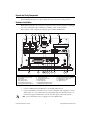
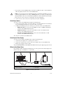
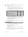
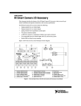
Getting Started with the NI EVS-1464 The NI EVS-1464 is a fanless embedded vision system designed for rugged industrial applications. The NI EVS-1464 features a Windows operating system and a variety of digital I/O and industrial communication connectors, including two IEEE 1394b1 bilingual interfaces and reconfigurable I/O (RIO). The NI EVS-1464 supports IEEE 1394 cameras, GigE Vision cameras and DirectShow-compatible USB cameras. This document describes how to install the NI EVS-1464 hardware and acquire an initial image. Refer to the NI EVS-1464 Series User Manual for device and I/O specifications, mounting requirements, and answers to common questions about network, firewall, hardware, software, and power issues. To access the NI EVS-1464 Series User Manual, select Start»All Programs»National Instruments» Vision»Documentation»NI-IMAQ IO. What You Need to Get Started The following components are included in the NI EVS-1464 kit: ❑ ❑ ❑ ❑ NI EVS-1464 DVI splitter cable Three-position power connector NI Vision Acquisition Software DVD Required Hardware In addition to the items included in the NI EVS-1464 kit, the following components are necessary to set up and configure the NI EVS-1464. ❑ One of the following power supply options: Caution Use the NI EVS-1464 only with a 24 VDC, UL listed, limited power source (LPS) supply. The power supply will bear the UL listed mark, LPS. The power supply must also meet any safety and compliance requirements for the country of use. – PS-5 Power Supply, 24 VDC, 5 A, Universal Power Input (part number 778805-90) – Any 24 VDC ±10%, 70 W or greater power supply ❑ Development computer running Windows Vista/XP/2000 ❑ CAT 5 10/100Base-TX or CAT 5e or CAT 6 1000Base-T Ethernet cable Note A CAT 5e or CAT 6 1000Base-T Ethernet cable is required to achieve maximum 1,000 Mbps (Gigabit) Ethernet performance. CAT 5e and CAT 6 Ethernet cables adhere to higher electrical standards required for Gigabit Ethernet communication. CAT 5 cables are not guaranteed to meet the necessary electrical requirements. While CAT 5 cables may appear to work at 1,000 Mbps in some installations, CAT 5 cables are likely to cause increased bit errors resulting in degraded or unreliable network performance. 1 To connect an IEEE 1394a camera to the NI EVS-1464, you will need a 6-pin to 9-pin cable or a 6-pin to 9-pin adapter. ❑ One of the following types of cameras: – IEEE 1394 camera – GigE Vision camera – DirectShow-compatible USB camera ❑ One of the following cables, corresponding to your camera type: – 9-pin IEEE 1394 cable for connecting to IEEE 1394b cameras1 – Ethernet cable for connecting to GigE Vision cameras – USB cable for connecting to DirectShow-compatible USB cameras Optional Equipment National Instruments offers a variety of products for use with the NI EVS-1464, including the following: • NI Vision I/O Terminal Block and Prototyping Accessory (part number 779166-01)2 • Digital I/O cable and horizontal DIN rail terminal block (part number 778790-01)2 • Digital I/O cable and vertical DIN rail terminal block (part number 778791-01)2 Visit ni.com or call the National Instruments office nearest you for more specific information about these products. Safety Information The following section contains important safety information that you must follow when installing and using the hardware. Do not operate the hardware in a manner not specified in this document and in the user documentation. Misuse of the hardware can result in a hazard. You can compromise the safety protection if the hardware is damaged in any way. If the hardware is damaged, return it to National Instruments for repair. Clean the hardware with a soft, nonmetallic brush. Make sure that the hardware is completely dry and free from contaminants before returning it to service. Do not substitute parts or modify the hardware except as described in this document. Use the hardware only with the chassis, modules, accessories, and cables specified in the installation instructions or specifications. You must have all covers and filler panels installed during operation of the hardware. Do not operate the hardware in an explosive atmosphere or where there may be flammable gases or fumes unless the hardware is UL (U.S.) or Ex (EU) Certified and marked for hazardous locations. The hardware must be in a suitably rated IP 54 minimum enclosure for hazardous locations. Refer to the hardware’s user documentation for more information. You must insulate signal connections for the maximum voltage for which the hardware is rated. Do not exceed the maximum ratings for the hardware. Do not install wiring while the hardware is live with electrical signals. Do not remove or add connector blocks when power is connected to the system. Avoid contact between your body and the connector block signal when hot swapping hardware. Remove power from signal lines before connecting them to or disconnecting them from the hardware. 1 2 To connect an IEEE 1394a camera to the NI EVS-1464, you will need a 6-pin to 9-pin cable or a 6-pin to 9-pin adapter. When using this accessory with the NI EVS-1464, three of the digital I/O signals on the device are not accessible. Refer to the General-Purpose Digital I/O section of Chapter 2, LED Indicators, DIP Switches, and Connectors, in the NI EVS-1464 Series User Manual for more information. Getting Started with the NI EVS-1464 2 ni.com Operate the hardware only at or below Pollution Degree 2. Pollution is foreign matter in a solid, liquid, or gaseous state that can reduce dielectric strength or surface resistivity. The following is a description of pollution degrees: • Pollution Degree 1 means no pollution or only dry, nonconductive pollution occurs. The pollution has no influence. Typical level for sealed components or coated PCBs. • Pollution Degree 2 means that only nonconductive pollution occurs in most cases. Occasionally, however, a temporary conductivity caused by condensation must be expected. Typical level for most products. • Pollution Degree 3 means that conductive pollution occurs, or dry, nonconductive pollution occurs that becomes conductive due to condensation. Operate the hardware at or below the measurement category1 marked on the hardware label. Measurement circuits are subjected to working voltages2 and transient stresses (overvoltage) from the circuit to which they are connected during measurement or test. Measurement categories establish standard impulse withstand voltage levels that commonly occur in electrical distribution systems. The following is a description of measurement categories: • Measurement Category I is for measurements performed on circuits not directly connected to the electrical distribution system referred to as MAINS3 voltage. This category is for measurements of voltages from specially protected secondary circuits. Such voltage measurements include signal levels, special hardware, limited-energy parts of hardware, circuits powered by regulated low-voltage sources, and electronics. • Measurement Category II is for measurements performed on circuits directly connected to the electrical distribution system (MAINS3). This category refers to local-level electrical distribution, such as that provided by a standard wall outlet (for example, 115 AC voltage for U.S. or 230 AC voltage for Europe). Examples of Measurement Category II are measurements performed on household appliances, portable tools, and similar hardware. • Measurement Category III is for measurements performed in the building installation at the distribution level. This category refers to measurements on hard-wired hardware such as hardware in fixed installations, distribution boards, and circuit breakers. Other examples are wiring, including cables, bus bars, junction boxes, switches, socket outlets in the fixed installation, and stationary motors with permanent connections to fixed installations. • Measurement Category IV is for measurements performed at the primary electrical supply installation typically outside buildings. Examples include electricity meters and measurements on primary overcurrent protection devices and on ripple control units. To obtain the safety certification(s) for this product, visit ni.com/certification, search by model number or product line, and click the appropriate link in the Certification column. 1 2 3 Measurement categories, also referred to as overvoltage or installation categories, are defined in electrical safety standard IEC 61010-1 and IEC 60664-1. Working voltage is the highest rms value of an AC or DC voltage that can occur across any particular insulation. MAINS is defined as a hazardous live electrical supply system that powers hardware. Suitably rated measuring circuits may be connected to the MAINS for measuring purposes. © National Instruments Corporation 3 Getting Started with the NI EVS-1464 Electromagnetic Compatibility Information This hardware has been tested and found to comply with the applicable regulatory requirements and limits for electromagnetic compatibility (EMC) as indicated in the hardware’s Declaration of Conformity (DoC)1. These requirements and limits are designed to provide reasonable protection against harmful interference when the hardware is operated in the intended electromagnetic environment. In special cases, for example when either highly sensitive or noisy hardware is being used in close proximity, additional mitigation measures may have to be employed to minimize the potential for electromagnetic interference. While this hardware is compliant with the applicable regulatory EMC requirements, there is no guarantee that interference will not occur in a particular installation. To minimize the potential for the hardware to cause interference to radio and television reception or to experience unacceptable performance degradation, install and use this hardware in strict accordance with the instructions in the hardware documentation and the DoC1. If this hardware does cause interference with licensed radio communications services or other nearby electronics, which can be determined by turning the hardware off and on, you are encouraged to try to correct the interference by one or more of the following measures: • Reorient the antenna of the receiver (the device suffering interference). • Relocate the transmitter (the device generating interference) with respect to the receiver. • Plug the transmitter into a different outlet so that the transmitter and the receiver are on different branch circuits. Some hardware may require the use of a metal, shielded enclosure (windowless version) to meet the EMC requirements for special EMC environments such as, for marine use or in heavy industrial areas. Refer to the hardware’s user documentation and the DoC1 for product installation requirements. When the hardware is connected to a test object or to test leads, the system may become more sensitive to disturbances or may cause interference in the local electromagnetic environment. Operation of this hardware in a residential area is likely to cause harmful interference. Users are required to correct the interference at their own expense or cease operation of the hardware. Changes or modifications not expressly approved by National Instruments could void the user’s right to operate the hardware under the local regulatory rules. Thermal Considerations and Mounting To maximize the cooling efficiency of the NI EVS-1464, observe the following recommendations: • Mount the NI EVS-1464 on a thermally conductive surface. • Avoid static air environments. • Mount the NI EVS-1464 with the heatsink facing upward. If you mount the NI EVS-1464 on a wall or other vertical surface, mount the device so that the heat sink fins are vertical. Refer to the NI EVS-1464 Series User Manual for dimensional drawings, additional mounting information, and detailed device specifications. 1 The Declaration of Conformity (DoC) contains important EMC compliance information and instructions for the user or installer. To obtain the DoC for this product, visit ni.com/certification, search by model number or product line, and click the appropriate link in the Certification column. Getting Started with the NI EVS-1464 4 ni.com Unpack and Verify Components Remove the NI EVS-1464 from the package and inspect the device for any sign of damage. Notify National Instruments if the device appears damaged in any way. Do not use a damaged device. Hardware Installation Ensure that the AC input to the external power supply is disconnected before plugging in or unplugging any connector. Ground the unit to minimize the possibility of static electricity damage. Refer to Figure 1 while completing the following steps to install the NI EVS-1464. RESET NO APP 6 7 USER 1 5 CF MS/SL 4 3 SAFE MODE IP RESET 2 1 8 USER 2 USER 1 HDD POWER COMPACT FLASH INPUT 10-20V 90W MAX MXIex1 18 1 2 3 4 5 6 Primary Network Connector Secondary Network Connector Reset Switch Audio In Connector Audio Out Connector Safe Mode/IP Reset/No App/ User 1/CF Master/Slave Switches 17 7 8 9 10 11 12 13 IEEE 1394b CAM I SO ! DIGITAL I/O IEEE 1394b 16 15 14 13 12 User 2/User 1/HDD/Power LEDs CompactFlash Slot Power Supply Connector Grounding Lug DVI-I Connector IEEE 1394b Bilingual Connector ISO/CAM Power Status LEDs 11 10 14 15 16 17 18 9 IEEE 1394b Bilingual Connector RS-232 Serial Connector (COM1) MXI Express x1 Connector Digital I/O Connector USB Connectors Figure 1. NI EVS-1464 Connectors 1. Connect a USB keyboard and USB mouse to any available USB connector. 2. Connect a DVI monitor to the DVI connector, or use the DVI splitter cable (supplied) to connect a VGA monitor or to connect dual monitors. For independent displays in dual monitor mode, one monitor must support a DVI-D interface and the other must support a VGA analog interface. Note Connect all monitors before you supply power to the NI EVS-1464. © National Instruments Corporation 5 Getting Started with the NI EVS-1464 3. If you want to connect the NI EVS-1464 to a network, use an Ethernet cable to connect the Ethernet hub to the primary network connector on the NI EVS-1464. Caution To prevent data loss and to maintain the integrity of your Ethernet installation, do not use a cable longer than 100 m. If you are using a 1,000 Mbps Ethernet, use a CAT 5e or CAT 6 shielded twisted-pair Ethernet cable. Use a shielded twisted pair Ethernet cable for maximum signal integrity. Connect devices to other connectors as required by your system configuration. 4. Connect devices to other connectors as required by your system configuration. Connecting a Camera To connect a camera to the NI EVS-1464, Complete the following steps: 1. Connect the appropriate cable to your camera. Refer to your camera manufacturer documentation for specific instructions about how to connect the cable to your camera. 2. Complete the following step for your camera type to connect the camera to the NI EVS-1464: • IEEE 1394 Cameras—Connect the camera IEEE 1394 cable to an IEEE 1394b bilingual connector on the NI EVS-1464 front panel. • GigE Vision Cameras—Connect the camera Ethernet cable to an available network connector on the NI EVS-1464 front panel. • DirectShow-Compatible USB Cameras—Connect the camera USB cable to a USB connector on the NI EVS-1464 front panel. The camera is now attached to the NI EVS-1464. Connecting the Power Supply To connect a power supply to the NI EVS-1464, complete the following steps: 1. Connect the power supply to the 3-position power connector. 2. Connect the 3-position power connector to the power supply connector on the NI EVS-1464. 3. Plug the power supply cord into an outlet. The power LED will illuminate and the NI EVS-1464 will boot when the power supply is properly connected. Wiring Isolated Output Power Refer to Figure 2 while completing the following steps to connect power for the isolated outputs to the NI EVS-1464 using a terminal block or a custom cable. 1 1 2 2 3 NI EVS-1464 44-Pin D-Sub Cable 3 4 4 Optional Terminal Block Power Supply Figure 2. Connecting Isolated Power Getting Started with the NI EVS-1464 6 ni.com Caution Do not connect the NI EVS-1464 isolated power to a source less than 5 VDC or greater than 30 VDC. Doing so could damage the device. 1. Connect and secure the 44-pin D-SUB connector on the cable to the digital I/O connector on the NI EVS-1464. 2. If you are using a terminal block, connect the cable to the terminal block. 3. Connect the voltage output from the power supply to the Viso connection on the cable or terminal block. Table 1 lists the pin locations for the digital I/O connector and National Instruments accessories. Refer to the NI EVS-1464 Series User Manual or your accessory documentation for additional pin information. . Table 1. Isolated Power Supply Connection Options Connection Method Viso Ciso Digital I/O connector 10, 25 14, 26, 29, 33, 36, 39, 42 44-pin D-SUB to 37-pin DIN rail terminal block (part number 778790-01 or 778791-01) 17, 33 12, 16, 28, 32, 34 Viso terminal Ciso terminal 44-pin D-SUB to 37-pin NI Vision I/O Terminal Block and Prototyping Accessory (part number 779166-01) 4. Connect the common-mode output from the power supply to the Ciso connection on the cable or terminal block. Refer to Table 1 for pin information. 5. Connect any additional I/O signals necessary for your application to the appropriate signal on the cable or terminal block. Refer to the NI EVS-1464 Series User Manual or your accessory documentation for additional pin information. 6. If necessary, connect the power cord to the power supply. 7. Plug the power supply cord into an outlet. The orange ISO LED on the NI EVS-1464 front panel will illuminate when the NI EVS-1464 is on and an isolated power supply is properly connected. Acquiring an Image with MAX Complete the following steps to acquire an image using MAX: 1. Select Start»All Programs»National Instruments»Measurement & Automation to launch MAX. 2. Expand the Devices and Interfaces branch of the configuration tree. 3. Expand the NI-IMAQdx Devices branch. 4. Select a camera. 5. Click Snap to acquire a single image, or click Grab to acquire continuous images. Click Grab again to stop a continuous acquisition. The NI EVS-1464 is now configured and acquiring images. Use LabVIEW to create your application. Refer to the Where to Go from Here section for a list of documentation and other resources to help you set up and use the NI EVS-1464 in an application. © National Instruments Corporation 7 Getting Started with the NI EVS-1464 Acquiring an Image with Vision Builder AI The NI EVS-1464 includes Vision Builder AI for evaluation purposes. Visit ni.com/vision to purchase a license for Vision Builder AI. Complete the following steps to acquire an image using Vision Builder AI: 1. On the Vision Builder AI Welcome screen, click Configure Inspection. 2. In the Inspection Steps palette, select the Acquire Images tab. 3. Click the Acquire Image (1394, GigE, or USB) step. The property page for the step opens. 4. Click Acquire Single Image to acquire an image from the NI EVS-1464. 5. Click OK to add the step to the inspection. The device is now configured and acquiring images. Use Vision Builder AI to add and configure additional inspection steps to create your application. Refer to the Where to Go from Here section for a list of resources to help you set up and use the NI EVS-1464 in an application. Specifications Refer to the NI EVS-1464 Series User Manual for detailed device and I/O specifications. Environment NI EVS-1464 systems are intended for indoor use only. Maximum altitude..................................................2,000 m Pollution Degree (IEC 60664) ...............................2 Operating Environment Ambient temperature range ...................................0 °C to 45 °C (IEC 60068-2-1 and IEC 60068-2-2) Relative humidity range (IEC 60068-2-56.............10% to 90% noncondensing Caution Clean the NI EVS-1464 with a soft nonmetallic brush. Make sure that the system is completely dry and free from contaminants before powering-on the controller again. Storage Environment Ambient temperature range ...................................–40 °C to 70 °C (IEC 60068-2-1 and IEC 60068-2-2) Relative humidity range (IEC 60068-2-56) ........5% to 95% noncondensing Shock and Vibration Operational shock ..................................................30 g peak, half-sine, 11 ms pulse (Tested in accordance with IEC-60068-2-27. Test profile developed in accordance with MIL-PRF-28800F.) Random vibration Operating .......................................................5 to 500 Hz, 0.3 grms (with solid-state hard drive) Nonoperating .................................................5 to 500 Hz, 2.4 grms (Tested in accordance with IEC-60068-2-64. Nonoperating test profile exceeds the requirements of MIL-PRF-28800F, Class 3.) Getting Started with the NI EVS-1464 8 ni.com Safety This product is designed to meet the requirements of the following standards of safety for electrical equipment for measurement, control, and laboratory use: • IEC 61010-1, EN-61010-1 • UL 61010-1, CSA 61010-1 Note For UL and other safety certifications, refer to product label or the Online Product Certification section. Electromagnetic Compatibility This product meets the requirements of the following EMC standards for electrical equipment for measurement, control, and laboratory use: • EN 61326 (IEC 61326): Class A emissions; Basic immunity • EN 55011 (CISPR 11): Group 1, Class A emissions • AS/NZS CISPR 11: Group 1, Class A emissions • FCC 47 CFR Part 15B: Class A emissions • ICES-001: Class A emissions Note Note For the standards applied to assess the EMC of this product, refer to product label or the Online Product Certification section. Note Note For EMC compliance, operate this product according to the documentation. CE Compliance This product meets the essential requirements of applicable European Directives as follows: • 2006/95/EC; Low-Voltage Directive (safety) • 2004/108/EC; Electromagnetic Compatibility Directive (EMC) Online Product Certification Refer to the product Declaration of Conformity (DoC) for additional regulatory compliance information. To obtain product certifications and the DoC for this product, visit ni.com/certification, search by model number or product line, and click the appropriate link in the Certification column. Environmental Management National Instruments is committed to designing and manufacturing products in an environmentally responsible manner. NI recognizes that eliminating certain hazardous substances from our products is beneficial not only to the environment but also to NI customers. For additional environmental information, refer to the NI and the Environment Web page at ni.com/ environment. This page contains the environmental regulations and directives with which NI complies, as well as other environmental information not included in this document. Waste Electrical and Electronic Equipment (WEEE) EU Customers At the end of the product life cycle, all products must be sent to a WEEE recycling center. For more information about WEEE recycling centers, National Instruments WEEE initiatives, and compliance with WEEE Directive 2002/96/EC on Waste and Electronic Equipment, visit ni.com/environment/weee. © National Instruments Corporation 9 Getting Started with the NI EVS-1464 Battery Replacement and Disposal Battery Directive This device contains a long-life coin cell battery. If you need to replace it, use the Return Material Authorization (RMA) process or contact an authorized National Instruments service representative. For more information about compliance with the EU Battery Directive 2006/66/EC about Batteries and Accumulators and Waste Batteries and Accumulators, visit ni.com/environment/ batterydirective. Cd/Hg/Pb ⬉ᄤֵᙃѻક∵ᶧࠊㅵ⧚ࡲ⊩ ˄Ё RoHS˅ Ёᅶ᠋ National Instruments ヺড়Ё⬉ᄤֵᙃѻકЁ䰤ࠊՓ⫼ᶤѯ᳝ᆇ⠽䋼ᣛҸ (RoHS)DŽ ݇Ѣ National Instruments Ё RoHS ড়㾘ᗻֵᙃˈ䇋ⱏᔩ ni.com/environment/rohs_chinaDŽ (For information about China RoHS compliance, go to ni.com/environment/rohs_china.) Where to Go from Here The following documents and resources contain information you may find helpful as you set up and use the NI EVS-1464 in an application. Refer to the NI EVS-1464 Series User Manual for detailed information about: • Device and I/O specifications • Mounting requirements • Answers to common questions about network, firewall, hardware, software, and power issues Additional Resources for Vision Builder for Automated Inspection Users Refer to the NI Vision Builder for Automated Inspection Tutorial to learn how to perform basic machine vision techniques using Vision Builder AI. You can access the NI Vision Builder for Automated Inspection Tutorial and other documentation by selecting Start»All Programs»National Instruments» Vision Builder AI»Documentation. You can also access context help within Vision Builder AI by clicking the Show Context Help button on the Vision Builder AI toolbar. Examples of common Vision Builder AI inspections are installed to the <Vision Builder AI>\ Examples directory. Visit the NI Developer Zone at ni.com/zone for the latest example programs, tutorials, technical presentations, and a community area where you can share ideas, questions, and source code with developers around the world. Additional Resources for LabVIEW Users Documentation for LabVIEW is available from the Help menu on the LabVIEW toolbar. You can access documentation for the NI Vision Development Module by selecting Start»All Programs»National Instruments»Vision»Documentation»NI Vision. Documentation for the NI-IMAQdx driver software is available by selecting Start»All Programs» National Instruments»Vision»Documentation»NI-IMAQdx. Documentation for the NI-IMAQ I/O driver software is available by selecting Start»All Programs» National Instruments»Vision»Documentation»NI-IMAQ IO. Documentation for the MAX configuration software is available from the Help menu on the MAX toolbar. Specific information about using MAX with NI Vision hardware is available by selecting Help»Help Topics»NI Vision»NI-IMAQdx. Getting Started with the NI EVS-1464 10 ni.com Examples of image acquisitions and common machine vision inspections are installed to the <LabVIEW>\Examples\IMAQ and <LabVIEW>\Examples\Vision directories, where <LabVIEW> is the location where LabVIEW is installed. Visit the NI Developer Zone at ni.com/zone for the latest example programs, tutorials, technical presentations, and a community area where you can share ideas, questions, and source code with developers around the world. Where to Go for Support The National Instruments Web site is your complete resource for technical support. At ni.com/ support you have access to everything from troubleshooting and application development self-help resources to email and phone assistance from NI Application Engineers. A Declaration of Conformity (DoC) is our claim of compliance with the Council of the European Communities using the manufacturer’s declaration of conformity. This system affords the user protection for electronic compatibility (EMC) and product safety. You can obtain the DoC for your product by visiting ni.com/certification. If your product supports calibration, you can obtain the calibration certificate for your product at ni.com/calibration. National Instruments corporate headquarters is located at 11500 North Mopac Expressway, Austin, Texas, 78759-3504. National Instruments also has offices located around the world to help address your support needs. For telephone support in the United States, create your service request at ni.com/ support and follow the calling instructions or dial 512 795 8248. For telephone support outside the United States, contact your local branch office: Australia 1800 300 800, Austria 43 662 457990-0, Belgium 32 (0) 2 757 0020, Brazil 55 11 3262 3599, Canada 800 433 3488, China 86 21 5050 9800, Czech Republic 420 224 235 774, Denmark 45 45 76 26 00, Finland 358 (0) 9 725 72511, France 01 57 66 24 24, Germany 49 89 7413130, India 91 80 41190000, Israel 972 3 6393737, Italy 39 02 41309277, Japan 0120-527196, Korea 82 02 3451 3400, Lebanon 961 (0) 1 33 28 28, Malaysia 1800 887710, Mexico 01 800 010 0793, Netherlands 31 (0) 348 433 466, New Zealand 0800 553 322, Norway 47 (0) 66 90 76 60, Poland 48 22 328 90 10, Portugal 351 210 311 210, Russia 7 495 783 6851, Singapore 1800 226 5886, Slovenia 386 3 425 42 00, South Africa 27 0 11 805 8197, Spain 34 91 640 0085, Sweden 46 (0) 8 587 895 00, Switzerland 41 56 2005151, Taiwan 886 02 2377 2222, Thailand 662 278 6777, Turkey 90 212 279 3031, United Kingdom 44 (0) 1635 523545 © National Instruments Corporation 11 Getting Started with the NI EVS-1464 National Instruments, NI, ni.com, and LabVIEW are trademarks of National Instruments Corporation. Refer to the Terms of Use section on ni.com/legal for more information about National Instruments trademarks. Other product and company names mentioned herein are trademarks or trade names of their respective companies. For patents covering National Instruments products/technology, refer to the appropriate location: Help»Patents in your software, the patents.txt file on your media, or the National Instruments Patent Notice at ni.com/patents. © 2009 National Instruments Corporation. All rights reserved. 375149A-01 Dec09